
Hi all, I'd like to resurrect an old conversation. As we know, the current PIC is quickly running out of resources and maybe it's time to switch to a better platform. Two CAN buses are now desirable too. A microSD slot and direct USB connectivity wouldn't hurt either. I will probably have to design a similar hardware for myself, so I'd like to contribute to the OVMS by sharing the HW platform if you want; no strings attached of course, if you decide that there's no need for the upgrade, I'll keep on working on my project by myself! :) That said, I'd like to throw a few ideas to the table.
- MCU: I'd like to use an STM32 micro. They seem to be emerging as the standard choice for diy ARM projects, and this offers a few interesting opportunities: -Programming it in c/c++ with the manufacturer CMSIS standard libraries (boring) -Programming it with the mbed.org SDK. Unfortunately no dev boards are available with dual CAN bus, but it will be easy to move to the correct micro of the same series once most of the software is ironed out on a dev board like the https://mbed.org/platforms/ST-Nucleo-F302R8/ -Programming it with an RTOS. NuttX would be my choice, as it's the one used in the Ardupilot Pixhawk platform, and I'd like to learn it. This would mean a steeper starting curve, but a lot of flexibility later as a lot of stuff is handled on the OS level (network stacks, SD card & filesystems, multitasking...). FreeRTOS is a nice option too.
I'd like to use the STM32F405RG as it's the most similar to the one found on the Pixhawk, but of course I'm biased because of that, and that micro is quite overkill for the task. We can of course use a lower specced part and lose some RTOS fuctionality as long as it has 2 CAN buses.
MODEM: I have no experience in this field; is the SIM908 still a good choice or does anyone think that we should try new platforms? I like this, but I don't know if the price puts it out of budget: http://www.telit.com/telit/Pulsar/en_US.Store.display.1001./ge864-gps On the bright side, it can be programmed in python, so we can offload some of the work to the modem. This *could* allow us to free some space on the PIC, and keep that platform without changing MCU..
Enclosure: I think that, even with the new MCU, we can still fit the old enclosure. Is that ok, or should we think about a more automotive-friendly one? Maybe waterproof for the twizy?
And that's it. I think that the core SW developers should voice their opinion, as there is a lot of work to be done on that front. A huge problem will be keeping backwards compatibility to add features for the v2 users, so we should discuss about this too.
Regards MG

Take a look at GEVCU 5;
https://groups.google.com/forum/#!topic/gevcu-development/sukQFDW8yjc
I¹d like to produce a GEVCU 6 that adds GPS/GPRS and uses the CINCH waterproof enclosure giving us WiFi, BT, GPS, GPRS, isolated I/O, and 80MHz 32bit Arduino DUE compatible hardware.
I¹m prepared to finance the hardware development and even the cost of porting the OVMS software if the current developers are interested in this route forward.
IMO we would all benefit from a single hardware platform and GEVCU already has some serious money behind it and some cool libraries that might help OVMS grow.
Kevin Sharpe | Founder & Chair Trustees | Zero Carbon World, a UK Registered Charity
From: Mastro Gippo <gipmad@gmail.com> Reply-To: OVMS Developers <ovmsdev@lists.teslaclub.hk> Date: Monday, 16 June 2014 16:41 To: OVMS Developers <ovmsdev@lists.teslaclub.hk> Subject: [Ovmsdev] OVMS v3
Hi all, I'd like to resurrect an old conversation. As we know, the current PIC is quickly running out of resources and maybe it's time to switch to a better platform. Two CAN buses are now desirable too. A microSD slot and direct USB connectivity wouldn't hurt either. I will probably have to design a similar hardware for myself, so I'd like to contribute to the OVMS by sharing the HW platform if you want; no strings attached of course, if you decide that there's no need for the upgrade, I'll keep on working on my project by myself! :) That said, I'd like to throw a few ideas to the table.
- MCU: I'd like to use an STM32 micro. They seem to be emerging as the standard choice for diy ARM projects, and this offers a few interesting opportunities: -Programming it in c/c++ with the manufacturer CMSIS standard libraries (boring) -Programming it with the mbed.org <http://mbed.org> SDK. Unfortunately no dev boards are available with dual CAN bus, but it will be easy to move to the correct micro of the same series once most of the software is ironed out on a dev board like the https://mbed.org/platforms/ST-Nucleo-F302R8/ -Programming it with an RTOS. NuttX would be my choice, as it's the one used in the Ardupilot Pixhawk platform, and I'd like to learn it. This would mean a steeper starting curve, but a lot of flexibility later as a lot of stuff is handled on the OS level (network stacks, SD card & filesystems, multitasking...). FreeRTOS is a nice option too.
I'd like to use the STM32F405RG as it's the most similar to the one found on the Pixhawk, but of course I'm biased because of that, and that micro is quite overkill for the task. We can of course use a lower specced part and lose some RTOS fuctionality as long as it has 2 CAN buses.
MODEM: I have no experience in this field; is the SIM908 still a good choice or does anyone think that we should try new platforms? I like this, but I don't know if the price puts it out of budget: http://www.telit.com/telit/Pulsar/en_US.Store.display.1001./ge864-gps On the bright side, it can be programmed in python, so we can offload some of the work to the modem. This *could* allow us to free some space on the PIC, and keep that platform without changing MCU..
Enclosure: I think that, even with the new MCU, we can still fit the old enclosure. Is that ok, or should we think about a more automotive-friendly one? Maybe waterproof for the twizy?
And that's it. I think that the core SW developers should voice their opinion, as there is a lot of work to be done on that front. A huge problem will be keeping backwards compatibility to add features for the v2 users, so we should discuss about this too.
Regards MG _______________________________________________ OvmsDev mailing list OvmsDev@lists.teslaclub.hkhttp://lists.teslaclub.hk/mailman/listinfo/ovmsdev

My biggest worry would be keeping the end user price similar to what it is now. Some routes would allow this, but some would put it out of the reach of lots of potential customers.
What would the likely cost implications of each of the suggested routes be?
Matt Beard
On Monday, 16 June 2014, Kevin Sharpe <kevin.sharpe@zerocarbonworld.org> wrote:
Take a look at GEVCU 5;
https://groups.google.com/forum/#!topic/gevcu-development/sukQFDW8yjc
I’d like to produce a GEVCU 6 that adds GPS/GPRS and uses the CINCH waterproof enclosure giving us WiFi, BT, GPS, GPRS, isolated I/O, and 80MHz 32bit Arduino DUE compatible hardware.
I’m prepared to finance the hardware development and even the cost of porting the OVMS software if the current developers are interested in this route forward.
IMO we would all benefit from a single hardware platform and GEVCU already has some serious money behind it and some cool libraries that might help OVMS grow.
Kevin Sharpe | Founder & Chair Trustees | Zero Carbon World, a UK Registered Charity
From: Mastro Gippo <gipmad@gmail.com <javascript:_e(%7B%7D,'cvml','gipmad@gmail.com');>> Reply-To: OVMS Developers <ovmsdev@lists.teslaclub.hk <javascript:_e(%7B%7D,'cvml','ovmsdev@lists.teslaclub.hk');>> Date: Monday, 16 June 2014 16:41 To: OVMS Developers <ovmsdev@lists.teslaclub.hk <javascript:_e(%7B%7D,'cvml','ovmsdev@lists.teslaclub.hk');>> Subject: [Ovmsdev] OVMS v3
Hi all, I'd like to resurrect an old conversation. As we know, the current PIC is quickly running out of resources and maybe it's time to switch to a better platform. Two CAN buses are now desirable too. A microSD slot and direct USB connectivity wouldn't hurt either. I will probably have to design a similar hardware for myself, so I'd like to contribute to the OVMS by sharing the HW platform if you want; no strings attached of course, if you decide that there's no need for the upgrade, I'll keep on working on my project by myself! :) That said, I'd like to throw a few ideas to the table.
- MCU: I'd like to use an STM32 micro. They seem to be emerging as the standard choice for diy ARM projects, and this offers a few interesting opportunities: -Programming it in c/c++ with the manufacturer CMSIS standard libraries (boring) -Programming it with the mbed.org SDK. Unfortunately no dev boards are available with dual CAN bus, but it will be easy to move to the correct micro of the same series once most of the software is ironed out on a dev board like the https://mbed.org/platforms/ST-Nucleo-F302R8/ -Programming it with an RTOS. NuttX would be my choice, as it's the one used in the Ardupilot Pixhawk platform, and I'd like to learn it. This would mean a steeper starting curve, but a lot of flexibility later as a lot of stuff is handled on the OS level (network stacks, SD card & filesystems, multitasking...). FreeRTOS is a nice option too.
I'd like to use the STM32F405RG as it's the most similar to the one found on the Pixhawk, but of course I'm biased because of that, and that micro is quite overkill for the task. We can of course use a lower specced part and lose some RTOS fuctionality as long as it has 2 CAN buses.
MODEM: I have no experience in this field; is the SIM908 still a good choice or does anyone think that we should try new platforms? I like this, but I don't know if the price puts it out of budget: http://www.telit.com/telit/Pulsar/en_US.Store.display.1001./ge864-gps On the bright side, it can be programmed in python, so we can offload some of the work to the modem. This *could* allow us to free some space on the PIC, and keep that platform without changing MCU..
Enclosure: I think that, even with the new MCU, we can still fit the old enclosure. Is that ok, or should we think about a more automotive-friendly one? Maybe waterproof for the twizy?
And that's it. I think that the core SW developers should voice their opinion, as there is a lot of work to be done on that front. A huge problem will be keeping backwards compatibility to add features for the v2 users, so we should discuss about this too.
Regards MG _______________________________________________ OvmsDev mailing list OvmsDev@lists.teslaclub.hk <javascript:_e(%7B%7D,'cvml','OvmsDev@lists.teslaclub.hk');> http://lists.teslaclub.hk/mailman/listinfo/ovmsdev
GEVCU 5 BOM is $200 using Mouser list prices but that excludes a GPS/GSM Modem.
In production quantities I believe you could hit $200 for an assembled and tested unit that¹s functionally compatible with the current OVMS but in waterproof case, with I/O, expanded memory, etc., etc. Adding BT and WiFi would probably add $50.
Obviously these prices are only justifiable if it adds a lot to the functionality to the car but given multiple CAN buses, lots memory, and CPU performance, I could imagine all sorts of navigation and control enhancements would be possible. The web server in the current GEVCU for example will revolutionise the way people customise the performance of their EV in future.
Personally I think functionality is more important than price in this upgrade market and one of the things holding back OVMS is the lack of developers working on the project. That¹s why I think GEVCU will be successful because its Arduino based hardware allows open hardware and software reuse.
Kevin Sharpe | Founder & Chair Trustees | Zero Carbon World, a UK Registered Charity
From: Matt Beard <matt@beard.tv> Reply-To: OVMS Developers <ovmsdev@lists.teslaclub.hk> Date: Monday, 16 June 2014 18:38 To: OVMS Developers <ovmsdev@lists.teslaclub.hk> Subject: Re: [Ovmsdev] OVMS v3
My biggest worry would be keeping the end user price similar to what it is now. Some routes would allow this, but some would put it out of the reach of lots of potential customers.
What would the likely cost implications of each of the suggested routes be?
Matt Beard
On Monday, 16 June 2014, Kevin Sharpe <kevin.sharpe@zerocarbonworld.org> wrote:
Take a look at GEVCU 5;
https://groups.google.com/forum/#!topic/gevcu-development/sukQFDW8yjc
I¹d like to produce a GEVCU 6 that adds GPS/GPRS and uses the CINCH waterproof enclosure giving us WiFi, BT, GPS, GPRS, isolated I/O, and 80MHz 32bit Arduino DUE compatible hardware.
I¹m prepared to finance the hardware development and even the cost of porting the OVMS software if the current developers are interested in this route forward.
IMO we would all benefit from a single hardware platform and GEVCU already has some serious money behind it and some cool libraries that might help OVMS grow.
Kevin Sharpe | Founder & Chair Trustees | Zero Carbon World, a UK Registered Charity
From: Mastro Gippo <gipmad@gmail.com <javascript:_e(%7B%7D,'cvml','gipmad@gmail.com');> > Reply-To: OVMS Developers <ovmsdev@lists.teslaclub.hk <javascript:_e(%7B%7D,'cvml','ovmsdev@lists.teslaclub.hk');> > Date: Monday, 16 June 2014 16:41 To: OVMS Developers <ovmsdev@lists.teslaclub.hk <javascript:_e(%7B%7D,'cvml','ovmsdev@lists.teslaclub.hk');> > Subject: [Ovmsdev] OVMS v3
Hi all, I'd like to resurrect an old conversation. As we know, the current PIC is quickly running out of resources and maybe it's time to switch to a better platform. Two CAN buses are now desirable too. A microSD slot and direct USB connectivity wouldn't hurt either. I will probably have to design a similar hardware for myself, so I'd like to contribute to the OVMS by sharing the HW platform if you want; no strings attached of course, if you decide that there's no need for the upgrade, I'll keep on working on my project by myself! :) That said, I'd like to throw a few ideas to the table.
- MCU: I'd like to use an STM32 micro. They seem to be emerging as the standard choice for diy ARM projects, and this offers a few interesting opportunities: -Programming it in c/c++ with the manufacturer CMSIS standard libraries (boring) -Programming it with the mbed.org <http://mbed.org> SDK. Unfortunately no dev boards are available with dual CAN bus, but it will be easy to move to the correct micro of the same series once most of the software is ironed out on a dev board like the https://mbed.org/platforms/ST-Nucleo-F302R8/ -Programming it with an RTOS. NuttX would be my choice, as it's the one used in the Ardupilot Pixhawk platform, and I'd like to learn it. This would mean a steeper starting curve, but a lot of flexibility later as a lot of stuff is handled on the OS level (network stacks, SD card & filesystems, multitasking...). FreeRTOS is a nice option too.
I'd like to use the STM32F405RG as it's the most similar to the one found on the Pixhawk, but of course I'm biased because of that, and that micro is quite overkill for the task. We can of course use a lower specced part and lose some RTOS fuctionality as long as it has 2 CAN buses.
MODEM: I have no experience in this field; is the SIM908 still a good choice or does anyone think that we should try new platforms? I like this, but I don't know if the price puts it out of budget: http://www.telit.com/telit/Pulsar/en_US.Store.display.1001./ge864-gps On the bright side, it can be programmed in python, so we can offload some of the work to the modem. This *could* allow us to free some space on the PIC, and keep that platform without changing MCU..
Enclosure: I think that, even with the new MCU, we can still fit the old enclosure. Is that ok, or should we think about a more automotive-friendly one? Maybe waterproof for the twizy?
And that's it. I think that the core SW developers should voice their opinion, as there is a lot of work to be done on that front. A huge problem will be keeping backwards compatibility to add features for the v2 users, so we should discuss about this too.
Regards MG _______________________________________________ OvmsDev mailing list OvmsDev@lists.teslaclub.hk <javascript:_e(%7B%7D,'cvml','OvmsDev@lists.teslaclub.hk');> http://lists.teslaclub.hk/mailman/listinfo/ovmsdev _______________________________________________ OvmsDev mailing list OvmsDev@lists.teslaclub.hkhttp://lists.teslaclub.hk/mailman/listinfo/ovmsdev
Maybe the important thing to ask at the moment is: What features do we want v3 to have?
I will start with a few from my wish-list:
- The ability to use 3G networks
- The ability to perform over-the air updates
- The ability to log trips or time-periods, ideally with a really easy way to extract the data
- A web interface that allows me to configure the unit easily, this may be via a common server that sends config to the device
- Fast turnaround of support for new vehicles of versions (this probably means making life easier for developers)
As a developer:
- USB comms rather than RS232 for debug
- The ability to download test code via USB without needing to open the box and use a proprietary programmer
- Ideally the ability to debug and program via the internet rather than needing physical access to the device (security will be important - this option should be disabled when shipped)
- The ability to use the device to do smart logging of the CAN bus - I think this may really help development on new vehicles, especially if it can be connected to a new vehicle and the data logged by a remote developer (rather than needing to wait for a developer to buy a car before support can be started)
Matt Beard
On Monday, June 16, 2014, Kevin Sharpe <kevin.sharpe@zerocarbonworld.org> wrote:
GEVCU 5 BOM is $200 using Mouser list prices but that excludes a GPS/GSM Modem.
In production quantities I believe you could hit $200 for an assembled and tested unit that’s functionally compatible with the current OVMS but in waterproof case, with I/O, expanded memory, etc., etc. Adding BT and WiFi would probably add $50.
Obviously these prices are only justifiable if it adds a lot to the functionality to the car… but given multiple CAN buses, lots memory, and CPU performance, I could imagine all sorts of navigation and control enhancements would be possible. The web server in the current GEVCU for example will revolutionise the way people customise the performance of their EV in future.
Personally I think functionality is more important than price in this upgrade market and one of the things holding back OVMS is the lack of developers working on the project. That’s why I think GEVCU will be successful because its Arduino based hardware allows open hardware and software reuse.
Kevin Sharpe | Founder & Chair Trustees | Zero Carbon World, a UK Registered Charity
From: Matt Beard <matt@beard.tv <javascript:_e(%7B%7D,'cvml','matt@beard.tv');>> Reply-To: OVMS Developers <ovmsdev@lists.teslaclub.hk <javascript:_e(%7B%7D,'cvml','ovmsdev@lists.teslaclub.hk');>> Date: Monday, 16 June 2014 18:38 To: OVMS Developers <ovmsdev@lists.teslaclub.hk <javascript:_e(%7B%7D,'cvml','ovmsdev@lists.teslaclub.hk');>> Subject: Re: [Ovmsdev] OVMS v3
My biggest worry would be keeping the end user price similar to what it is now. Some routes would allow this, but some would put it out of the reach of lots of potential customers.
What would the likely cost implications of each of the suggested routes be?
Matt Beard
On Monday, 16 June 2014, Kevin Sharpe <kevin.sharpe@zerocarbonworld.org> wrote:
Take a look at GEVCU 5;
https://groups.google.com/forum/#!topic/gevcu-development/sukQFDW8yjc
I’d like to produce a GEVCU 6 that adds GPS/GPRS and uses the CINCH waterproof enclosure giving us WiFi, BT, GPS, GPRS, isolated I/O, and 80MHz 32bit Arduino DUE compatible hardware.
I’m prepared to finance the hardware development and even the cost of porting the OVMS software if the current developers are interested in this route forward.
IMO we would all benefit from a single hardware platform and GEVCU already has some serious money behind it and some cool libraries that might help OVMS grow.
Kevin Sharpe | Founder & Chair Trustees | Zero Carbon World, a UK Registered Charity
From: Mastro Gippo <gipmad@gmail.com> Reply-To: OVMS Developers <ovmsdev@lists.teslaclub.hk> Date: Monday, 16 June 2014 16:41 To: OVMS Developers <ovmsdev@lists.teslaclub.hk> Subject: [Ovmsdev] OVMS v3
Hi all, I'd like to resurrect an old conversation. As we know, the current PIC is quickly running out of resources and maybe it's time to switch to a better platform. Two CAN buses are now desirable too. A microSD slot and direct USB connectivity wouldn't hurt either. I will probably have to design a similar hardware for myself, so I'd like to contribute to the OVMS by sharing the HW platform if you want; no strings attached of course, if you decide that there's no need for the upgrade, I'll keep on working on my project by myself! :) That said, I'd like to throw a few ideas to the table.
- MCU: I'd like to use an STM32 micro. They seem to be emerging as the standard choice for diy ARM projects, and this offers a few interesting opportunities: -Programming it in c/c++ with the manufacturer CMSIS standard libraries (boring) -Programming it with the mbed.org SDK. Unfortunately no dev boards are available with dual CAN bus, but it will be easy to move to the correct micro of the same series once most of the software is ironed out on a dev board like the https://mbed.org/platforms/ST-Nucleo-F302R8/ -Programming it with an RTOS. NuttX would be my choice, as it's the one used in the Ardupilot Pixhawk platform, and I'd like to learn it. This would mean a steeper starting curve, but a lot of flexibility later as a lot of stuff is handled on the OS level (network stacks, SD card & filesystems, multitasking...). FreeRTOS is a nice option too.
I'd like to use the STM32F405RG as it's the most similar to the one found on the Pixhawk, but of course I'm biased because of that, and that micro is quite overkill for the task. We can of course use a lower specced part and lose some RTOS fuctionality as long as it has 2 CAN buses.
- MODEM: I have no experience in this field; is the SIM908 still a good choice or does anyone think that we should try new platforms? I like this, but I don't know if the price puts it out of budget: http://www.telit.com/telit/Pulsar/en_US.Store.display.1001./ge864- <http://www.telit.com/telit/Pulsar/en_US.Store.display.1001./ge864-gps>

I want to say "amen" to both Kevin's and Matt's comments.
Right now it's really only fully useful for Roadster (and Model S) owners. Volt/Ampera owners (and Leaf and Twizzy?) can remotely get a limited amount of incredibly useful information (like SOC), but the degree of control that the Roaster owners have isn't there (locking, unlocking, pre-heating/cooling, etc.).
I intend to develop-in some of these features over time - at least for Volt/Ampera, and the only thing that has me not yet doing that is my need to get up-to-speed on the development environment and methods.
However, even if all of the features available to Roadster owners were there for everyone, there is still so much more potential, as Kevin and Matt have said.
If something isn't done to enable the expanded use then OVMS will continually only cater to a limited audience: one that wants access to various remote-control and remote-tracking features, but with limited local (in-car) usability and limited developer appeal.
Thanks,
Lee.
-- *Lee Howard* *Mainpine, Inc. Chief Technology Officer* Tel: +1 866 363 6680 | Fax: +1 360 462 8160 lee.howard@mainpine.com | www.mainpine.com
Kevin, I just read that thread, thanks. I usually dislike Rickard's attitude, but he has a point, the 2 products are for different purposes even if sometimes they somehow match (someone adds GSM to the GEVCU, someone adds outputs for relays and stuff to the OVMS). I saw the GEVCU project a while ago and didn't like it much, mostly for Rickard's involvement, and also because it was quite "amateur", but now at ver 5 it starts to look more professional. The question is - do we want to step up the game and start making a truly automotive device? The answer is no, because it involves HUGE investments and a very structured company to respect al the standards, but we should at least try to do our best with our limited resources, and the GEVCU 5 seems to have taken this direction quite seriously. This is only because they will actually mess with the car's internals; as a mostly read-only interface, OVMS doesn't need that much safety. The price problem is very important, as the OVMS is mostly an end user "gadget", while the GEVCU aims to be a real ECU. So OVMS have to keep a low price point. Unfortunately the CINCH cases cost a lot, as Jack said in that thread "A BOM isn't a product. We have more in enclosure and cable than we have in the circuit board very nearly." so we must keep on using "chinese" enclosures, but this doesn't stop us from looking for a better one.
I don't really like the Arduino environment, but if that makes the product more desirable we can go that way, as it should also significantly reduce development cost.
Matt, the new platform should very easily solve all your points, but the 3G modem is still a big question mark for me. Do we really need it? going 3G means higher service prices (especially for international contracts), and you sometimes don't even have coverage.. should consume more current too. A way to share the 3G connection with other devices (streaming radio...) would make up for the higher connection cost.
I think that an RTOS/OS will be very useful in that way, as people can add and remove modules as they will, but this requires a lot of effort (to implement it on a micro) or a powerful and power hungry device. A very cool thing would be to pair a small cheap router running linux ( http://wiki.openwrt.org/toh/tp-link/tl-wr702n for ~18$ or http://wiki.openwrt.org/toh/8devices/carambola for ~25$ ) with an USB 3G modem and a custom USB-CAN adapter (that can even be later used for development, and sold as a product by itself!). But this is quite an hack, and while adding extremely easy development, almost infinite expansion capabilities and wifi out of the box, it's not a very consumer product. Heck, it can even get streaming radios to the audio system with an usb audio card! (I'm just brainstorming, but I like this idea more the more I think about it...)
MG
2014-06-16 20:55 GMT+02:00 Lee Howard <lee.howard@mainpine.com>:
I want to say "amen" to both Kevin's and Matt's comments.
Right now it's really only fully useful for Roadster (and Model S) owners. Volt/Ampera owners (and Leaf and Twizzy?) can remotely get a limited amount of incredibly useful information (like SOC), but the degree of control that the Roaster owners have isn't there (locking, unlocking, pre-heating/cooling, etc.).
I intend to develop-in some of these features over time - at least for Volt/Ampera, and the only thing that has me not yet doing that is my need to get up-to-speed on the development environment and methods.
However, even if all of the features available to Roadster owners were there for everyone, there is still so much more potential, as Kevin and Matt have said.
If something isn't done to enable the expanded use then OVMS will continually only cater to a limited audience: one that wants access to various remote-control and remote-tracking features, but with limited local (in-car) usability and limited developer appeal.
Thanks,
Lee.
-- *Lee Howard* *Mainpine, Inc. Chief Technology Officer* Tel: +1 866 363 6680 | Fax: +1 360 462 8160 lee.howard@mainpine.com | www.mainpine.com
OvmsDev mailing list OvmsDev@lists.teslaclub.hk http://lists.teslaclub.hk/mailman/listinfo/ovmsdev

Twizy users don't need locking / pre-heating etc., the controller parameter tuning is the currently most important Twizy OVMS feature (not available on other cars up to now).
Twizy user feedback:
The current OVMS is far too complex for normal people.
GSM is good as an option, but bad as a requirement. Needing to buy and insert a SIM card is already too much for many. GSM reliability and availability also is an issue for serious telemetry. The most simple logging setup should work with just an SD / USB memory stick, readable on any PC.
An OVMS v3 core version should be able to work with just a local Wifi / Bluetooth / USB connection. That could mean the GSM/GPS module becomes an extension module.
An optional separate display console could make it possible to use the OVMS even without a smartphone / laptop.
Software updates need to be possible without unmounting the OVMS, the PICkit flash procedure is way too much for ordinary users.
Average power consumption needs to be lower than now by a factor of ~10, it's bad needing to remember unplugging the OVMS if you leave for a week.
OVMS v3 also needs an ECE approval so it can be sold legally in Europe. Price may be higher than now then, by about 50-100%.
Linux would be great and would open the path to a broad user community, but I doubt that can be combined with the low power usage and pricing requirements... although, the Samsung NX300 shows it's already been done -- I have no idea about their hardware base though.
Regards, Michael
Am 16.06.2014 20:55, schrieb Lee Howard:
I want to say "amen" to both Kevin's and Matt's comments.
Right now it's really only fully useful for Roadster (and Model S) owners. Volt/Ampera owners (and Leaf and Twizzy?) can remotely get a limited amount of incredibly useful information (like SOC), but the degree of control that the Roaster owners have isn't there (locking, unlocking, pre-heating/cooling, etc.).
I intend to develop-in some of these features over time - at least for Volt/Ampera, and the only thing that has me not yet doing that is my need to get up-to-speed on the development environment and methods.
However, even if all of the features available to Roadster owners were there for everyone, there is still so much more potential, as Kevin and Matt have said.
If something isn't done to enable the expanded use then OVMS will continually only cater to a limited audience: one that wants access to various remote-control and remote-tracking features, but with limited local (in-car) usability and limited developer appeal.
Thanks,
Lee.
-- Michael Balzer * Paradestr. 8 * D-42107 Wuppertal Fon 0202 / 272 2201 * Handy 0176 / 206 989 26
Michael, oddly enough the Wifi+bluetooth may cost more and be harder to develop than a GSM modem... and an OVMS with only USB / BT / WIFI conection would then become only slightly better than an ELM327. Lowering power consumption is nearly impossible because of the required connection, but we can make an option for the twizy to turn off the modem when the car is not charging or is not on. It shouldn't be an issue because having a connection is useless anyway as the twizy doesn't have things (A/C) to remotely control when the car is turned off. What are you talking about the Samsung NX300? I don't see anything impressive, 160 minutes of battery time on 1100mah is pretty standard... MG
2014-06-16 22:22 GMT+02:00 Michael Balzer <dexter@expeedo.de>:
Twizy users don't need locking / pre-heating etc., the controller parameter tuning is the currently most important Twizy OVMS feature (not available on other cars up to now).
Twizy user feedback:
The current OVMS is far too complex for normal people.
GSM is good as an option, but bad as a requirement. Needing to buy and insert a SIM card is already too much for many. GSM reliability and availability also is an issue for serious telemetry. The most simple logging setup should work with just an SD / USB memory stick, readable on any PC.
An OVMS v3 core version should be able to work with just a local Wifi / Bluetooth / USB connection. That could mean the GSM/GPS module becomes an extension module.
An optional separate display console could make it possible to use the OVMS even without a smartphone / laptop.
Software updates need to be possible without unmounting the OVMS, the PICkit flash procedure is way too much for ordinary users.
Average power consumption needs to be lower than now by a factor of ~10, it's bad needing to remember unplugging the OVMS if you leave for a week.
OVMS v3 also needs an ECE approval so it can be sold legally in Europe. Price may be higher than now then, by about 50-100%.
Linux would be great and would open the path to a broad user community, but I doubt that can be combined with the low power usage and pricing requirements... although, the Samsung NX300 shows it's already been done -- I have no idea about their hardware base though.
Regards, Michael
-- Michael Balzer * Paradestr. 8 * D-42107 Wuppertal Fon 0202 / 272 2201 * Handy 0176 / 206 989 26
OvmsDev mailing list OvmsDev@lists.teslaclub.hk http://lists.teslaclub.hk/mailman/listinfo/ovmsdev

I think it's incredibly valuable to keep the $100 price point.
It seems to me that the hard part of adding support for other vehicles is figuring out the CAN bus codes. That's ideally done with hardware optimized for that task, which is probably not the OVMS device. There's so much framework already in place that once you know how to read values and issue commands, getting that into OVMS isn't that hard.
Making OVMS more expensive to better serve the developer community will make it a harder buying decision for end users. Hopefully, we'll eventually have thousands of users for every developer.
It would, of course, be an improvement to make firmware updates easier for end users, that is an important issue.
I would like to see some sort of display, either on the box or remote, so I can see SOC in the car without using a phone.
Tom
-----Original Message----- From: Lee Howard <lee.howard@mainpine.com> Reply-To: OVMS Developers <ovmsdev@lists.teslaclub.hk> Date: Monday, June 16, 2014 at 11:55 AM To: OVMS Developers <ovmsdev@lists.teslaclub.hk> Subject: Re: [Ovmsdev] OVMS v3
I want to say "amen" to both Kevin's and Matt's comments.
Right now it's really only fully useful for Roadster (and Model S) owners. Volt/Ampera owners (and Leaf and Twizzy?) can remotely get a limited amount of incredibly useful information (like SOC), but the degree of control that the Roaster owners have isn't there (locking, unlocking, pre-heating/cooling, etc.).
I intend to develop-in some of these features over time - at least for Volt/Ampera, and the only thing that has me not yet doing that is my need to get up-to-speed on the development environment and methods.
However, even if all of the features available to Roadster owners were there for everyone, there is still so much more potential, as Kevin and Matt have said.
If something isn't done to enable the expanded use then OVMS will continually only cater to a limited audience: one that wants access to various remote-control and remote-tracking features, but with limited local (in-car) usability and limited developer appeal.
Thanks,
Lee.
-- *Lee Howard* *Mainpine, Inc. Chief Technology Officer* Tel: +1 866 363 6680 | Fax: +1 360 462 8160 lee.howard@mainpine.com | www.mainpine.com
OvmsDev mailing list OvmsDev@lists.teslaclub.hk http://lists.teslaclub.hk/mailman/listinfo/ovmsdev

What I'm wondering is how valuable it would be to have a device in the car capable of:
logging can bus traffic to SD card logging can bus traffic remotely (over wifi, etc) Issuing CAN bus requests remotely Receiving firmware updates remotely
And, what if that device was OVMS itself?
I know that when I am developing for OVMS, I spend a tremendous amount of time switching between OVMS and a CAN bus logger. Also, removing OVMS to program it, and plugging it back in again. My lousy cellular reception at home doesn't help (although has probably helped OVMS deal with lousy cellular reception situations quite well). My ideal device would be in the car always. It would allow me to log all traffic (or selected traffic with an easy start/stop/trigger), and remotely download those logs. It would allow me to make a change to the firmware, remotely, and see the impact. The issue would be doing all that while keeping security high as well as power consumption and price low.
Regarding the display, could this be bluetooth to an Android/iPhone? Or, do we need a physical display? With most of the device nowadays, adding a directly attached display is not too hard (and not too expensive) so long as it is on ribbon cable less than perhaps 6" away. But, if a remote display is required, that tends to drive up the price dramatically. It seems that the CPUs nowadays can directly control a display. But, if you want to run a remote display than you have to use UART (or something like that) and then run a separate CPU in the display itself.
Regards, Mark.
On 17 Jun, 2014, at 1:20 pm, Tom Saxton <tom@idleloop.com> wrote:
I think it's incredibly valuable to keep the $100 price point.
It seems to me that the hard part of adding support for other vehicles is figuring out the CAN bus codes. That's ideally done with hardware optimized for that task, which is probably not the OVMS device. There's so much framework already in place that once you know how to read values and issue commands, getting that into OVMS isn't that hard.
Making OVMS more expensive to better serve the developer community will make it a harder buying decision for end users. Hopefully, we'll eventually have thousands of users for every developer.
It would, of course, be an improvement to make firmware updates easier for end users, that is an important issue.
I would like to see some sort of display, either on the box or remote, so I can see SOC in the car without using a phone.
Tom
-----Original Message----- From: Lee Howard <lee.howard@mainpine.com> Reply-To: OVMS Developers <ovmsdev@lists.teslaclub.hk> Date: Monday, June 16, 2014 at 11:55 AM To: OVMS Developers <ovmsdev@lists.teslaclub.hk> Subject: Re: [Ovmsdev] OVMS v3
I want to say "amen" to both Kevin's and Matt's comments.
Right now it's really only fully useful for Roadster (and Model S) owners. Volt/Ampera owners (and Leaf and Twizzy?) can remotely get a limited amount of incredibly useful information (like SOC), but the degree of control that the Roaster owners have isn't there (locking, unlocking, pre-heating/cooling, etc.).
I intend to develop-in some of these features over time - at least for Volt/Ampera, and the only thing that has me not yet doing that is my need to get up-to-speed on the development environment and methods.
However, even if all of the features available to Roadster owners were there for everyone, there is still so much more potential, as Kevin and Matt have said.
If something isn't done to enable the expanded use then OVMS will continually only cater to a limited audience: one that wants access to various remote-control and remote-tracking features, but with limited local (in-car) usability and limited developer appeal.
Thanks,
Lee.
-- *Lee Howard* *Mainpine, Inc. Chief Technology Officer* Tel: +1 866 363 6680 | Fax: +1 360 462 8160 lee.howard@mainpine.com | www.mainpine.com
OvmsDev mailing list OvmsDev@lists.teslaclub.hk http://lists.teslaclub.hk/mailman/listinfo/ovmsdev
OvmsDev mailing list OvmsDev@lists.teslaclub.hk http://lists.teslaclub.hk/mailman/listinfo/ovmsdev
A couple of comments.
Firstly, adding a directly connected display means that the OVMS unit has to be mounted in clear view, not behind the dash.
Secondly, as more EVs get released there needs to be a solution to the problem that at the moment an OVMS developer needs to buy an EV of a particular model before there is any real hope of getting support for that type. Alternatively an owner of such an EV needs to be converted to being a developer. I think it would significantly help to a) lower the bar to becoming an OVMS developer (such as removing the need to buy lots of extra kit and spend much time installing/removing hardware from the car, or driving with laptop attached the car) and b) allow an OVMS developer to easily co-operate with an EV owner that may not be physically close by to read CAN data and try new code (so log CAN data and download details over GSM or 3G and load firmware remotely)
Matt Beard
On Tuesday, June 17, 2014, Mark Webb-Johnson <mark@webb-johnson.net> wrote:
What I'm wondering is how valuable it would be to have a device in the car capable of:
- logging can bus traffic to SD card
- logging can bus traffic remotely (over wifi, etc)
- Issuing CAN bus requests remotely
- Receiving firmware updates remotely
And, what if that device was OVMS itself?
I know that when I am developing for OVMS, I spend a tremendous amount of time switching between OVMS and a CAN bus logger. Also, removing OVMS to program it, and plugging it back in again. My lousy cellular reception at home doesn't help (although has probably helped OVMS deal with lousy cellular reception situations quite well). My ideal device would be in the car always. It would allow me to log all traffic (or selected traffic with an easy start/stop/trigger), and remotely download those logs. It would allow me to make a change to the firmware, remotely, and see the impact. The issue would be doing all that while keeping security high as well as power consumption and price low.
Regarding the display, could this be bluetooth to an Android/iPhone? Or, do we need a physical display? With most of the device nowadays, adding a directly attached display is not too hard (and not too expensive) so long as it is on ribbon cable less than perhaps 6" away. But, if a remote display is required, that tends to drive up the price dramatically. It seems that the CPUs nowadays can directly control a display. But, if you want to run a remote display than you have to use UART (or something like that) and then run a separate CPU in the display itself.
Regards, Mark.
On 17 Jun, 2014, at 1:20 pm, Tom Saxton <tom@idleloop.com <javascript:_e(%7B%7D,'cvml','tom@idleloop.com');>> wrote:
I think it's incredibly valuable to keep the $100 price point.
It seems to me that the hard part of adding support for other vehicles is figuring out the CAN bus codes. That's ideally done with hardware optimized for that task, which is probably not the OVMS device. There's so much framework already in place that once you know how to read values and issue commands, getting that into OVMS isn't that hard.
Making OVMS more expensive to better serve the developer community will make it a harder buying decision for end users. Hopefully, we'll eventually have thousands of users for every developer.
It would, of course, be an improvement to make firmware updates easier for end users, that is an important issue.
I would like to see some sort of display, either on the box or remote, so I can see SOC in the car without using a phone.
Tom
-----Original Message----- From: Lee Howard <lee.howard@mainpine.com <javascript:_e(%7B%7D,'cvml','lee.howard@mainpine.com');>> Reply-To: OVMS Developers <ovmsdev@lists.teslaclub.hk <javascript:_e(%7B%7D,'cvml','ovmsdev@lists.teslaclub.hk');>> Date: Monday, June 16, 2014 at 11:55 AM To: OVMS Developers <ovmsdev@lists.teslaclub.hk <javascript:_e(%7B%7D,'cvml','ovmsdev@lists.teslaclub.hk');>> Subject: Re: [Ovmsdev] OVMS v3
I want to say "amen" to both Kevin's and Matt's comments.
Right now it's really only fully useful for Roadster (and Model S) owners. Volt/Ampera owners (and Leaf and Twizzy?) can remotely get a limited amount of incredibly useful information (like SOC), but the degree of control that the Roaster owners have isn't there (locking, unlocking, pre-heating/cooling, etc.).
I intend to develop-in some of these features over time - at least for Volt/Ampera, and the only thing that has me not yet doing that is my need to get up-to-speed on the development environment and methods.
However, even if all of the features available to Roadster owners were there for everyone, there is still so much more potential, as Kevin and Matt have said.
If something isn't done to enable the expanded use then OVMS will continually only cater to a limited audience: one that wants access to various remote-control and remote-tracking features, but with limited local (in-car) usability and limited developer appeal.
Thanks,
Lee.
-- *Lee Howard* *Mainpine, Inc. Chief Technology Officer* Tel: +1 866 363 6680 | Fax: +1 360 462 8160 lee.howard@mainpine.com <javascript:_e(%7B%7D,'cvml','lee.howard@mainpine.com');> | www.mainpine.com
OvmsDev mailing list OvmsDev@lists.teslaclub.hk <javascript:_e(%7B%7D,'cvml','OvmsDev@lists.teslaclub.hk');> http://lists.teslaclub.hk/mailman/listinfo/ovmsdev
OvmsDev mailing list OvmsDev@lists.teslaclub.hk <javascript:_e(%7B%7D,'cvml','OvmsDev@lists.teslaclub.hk');> http://lists.teslaclub.hk/mailman/listinfo/ovmsdev
Matt,
Firstly, adding a directly connected display means that the OVMS unit has to be mounted in clear view, not behind the dash.
Yes, that is my concern. For my personal use case, I already have 3 displays in my car (the little VDS, a 2DIN Asteroid Parrot, and an iPhone) - not counting the speedometer. I could use either the Parrot or iPhone for an OVMS display without much impact to my daily routine.
So, I'm interested in the requirement for non-smartphone displays. I heard this originally from the Twizy owners, but it seems Tom sees a use as well.
I think it would significantly help to ... (snip) ... allow an OVMS developer to easily co-operate with an EV owner that may not be physically close by to read CAN data and try new code
Yes. My exact thinking.
My day job is CTO of a company that manages thousands of remote device in the field. It is amazingly efficient to be able to remotely connect for diagnostics and support.
If an owner can just buy and install an OVMS module, with the developer working remotely, we could leverage this much more.
Regards, Mark.
On 17 Jun, 2014, at 1:52 pm, Matt Beard <matt@beard.tv> wrote:
A couple of comments.
Firstly, adding a directly connected display means that the OVMS unit has to be mounted in clear view, not behind the dash.
Secondly, as more EVs get released there needs to be a solution to the problem that at the moment an OVMS developer needs to buy an EV of a particular model before there is any real hope of getting support for that type. Alternatively an owner of such an EV needs to be converted to being a developer. I think it would significantly help to a) lower the bar to becoming an OVMS developer (such as removing the need to buy lots of extra kit and spend much time installing/removing hardware from the car, or driving with laptop attached the car) and b) allow an OVMS developer to easily co-operate with an EV owner that may not be physically close by to read CAN data and try new code (so log CAN data and download details over GSM or 3G and load firmware remotely)
Matt Beard
On Tuesday, June 17, 2014, Mark Webb-Johnson <mark@webb-johnson.net> wrote:
What I'm wondering is how valuable it would be to have a device in the car capable of:
logging can bus traffic to SD card logging can bus traffic remotely (over wifi, etc) Issuing CAN bus requests remotely Receiving firmware updates remotely
And, what if that device was OVMS itself?
I know that when I am developing for OVMS, I spend a tremendous amount of time switching between OVMS and a CAN bus logger. Also, removing OVMS to program it, and plugging it back in again. My lousy cellular reception at home doesn't help (although has probably helped OVMS deal with lousy cellular reception situations quite well). My ideal device would be in the car always. It would allow me to log all traffic (or selected traffic with an easy start/stop/trigger), and remotely download those logs. It would allow me to make a change to the firmware, remotely, and see the impact. The issue would be doing all that while keeping security high as well as power consumption and price low.
Regarding the display, could this be bluetooth to an Android/iPhone? Or, do we need a physical display? With most of the device nowadays, adding a directly attached display is not too hard (and not too expensive) so long as it is on ribbon cable less than perhaps 6" away. But, if a remote display is required, that tends to drive up the price dramatically. It seems that the CPUs nowadays can directly control a display. But, if you want to run a remote display than you have to use UART (or something like that) and then run a separate CPU in the display itself.
Regards, Mark.
On 17 Jun, 2014, at 1:20 pm, Tom Saxton <tom@idleloop.com> wrote:
I think it's incredibly valuable to keep the $100 price point.
It seems to me that the hard part of adding support for other vehicles is figuring out the CAN bus codes. That's ideally done with hardware optimized for that task, which is probably not the OVMS device. There's so much framework already in place that once you know how to read values and issue commands, getting that into OVMS isn't that hard.
Making OVMS more expensive to better serve the developer community will make it a harder buying decision for end users. Hopefully, we'll eventually have thousands of users for every developer.
It would, of course, be an improvement to make firmware updates easier for end users, that is an important issue.
I would like to see some sort of display, either on the box or remote, so I can see SOC in the car without using a phone.
Tom
-----Original Message----- From: Lee Howard <lee.howard@mainpine.com> Reply-To: OVMS Developers <ovmsdev@lists.teslaclub.hk> Date: Monday, June 16, 2014 at 11:55 AM To: OVMS Developers <ovmsdev@lists.teslaclub.hk> Subject: Re: [Ovmsdev] OVMS v3
I want to say "amen" to both Kevin's and Matt's comments.
Right now it's really only fully useful for Roadster (and Model S) owners. Volt/Ampera owners (and Leaf and Twizzy?) can remotely get a limited amount of incredibly useful information (like SOC), but the degree of control that the Roaster owners have isn't there (locking, unlocking, pre-heating/cooling, etc.).
I intend to develop-in some of these features over time - at least for Volt/Ampera, and the only thing that has me not yet doing that is my need to get up-to-speed on the development environment and methods.
However, even if all of the features available to Roadster owners were there for everyone, there is still so much more potential, as Kevin and Matt have said.
If something isn't done to enable the expanded use then OVMS will continually only cater to a limited audience: one that wants access to various remote-control and remote-tracking features, but with limited local (in-car) usability and limited developer appeal.
Thanks,
Lee.
-- *Lee Howard* *Mainpine, Inc. Chief Technology Officer* Tel: +1 866 363 6680 | Fax: +1 360 462 8160 lee.howard@mainpine.com | www.mainpine.com
OvmsDev mailing list OvmsDev@lists.teslaclub.hk http://lists.teslaclub.hk/mailman/listinfo/ovmsdev
OvmsDev mailing list OvmsDev@lists.teslaclub.hk http://lists.teslaclub.hk/mailman/listinfo/ovmsdev
OvmsDev mailing list OvmsDev@lists.teslaclub.hk http://lists.teslaclub.hk/mailman/listinfo/ovmsdev
In our Leaf, we have a Gary Giddings SOC meter. It powers up with the car and shows the SOC on an LED display that's always easily visible day or night. It's positioned discretely so it doesn't clutter up the car yet is still easy to see with a quick glance. I don't want to have to fumble with a cell phone to look at SOC. We don't have a cell phone mount in the car as that would attract break-ins.
The Roadster is different because it has a good SOC display, so the OVMS is only used for remote monitoring, occasional control, plus now the incredibly useful ACC.
The newer Leafs have the option of showing a numerical SOC percent, but that's still relative to the current pack capacity rather than an absolute energy estimate. So, displaying something based on Gids would still be useful to new Leaf owners although it's a less obvious need now.
The 2014 Leaf removed the ability to limit charging to 80% because the EPA was punishing them for that feature (lowering the estimated range to the average of 100% and 80% charge, a very stupid move). Perhaps that doesn't make any difference in battery longevity, but it's a huge setback for owners (like me) who live at the top of a hill. When every charge is to 100%, you get no regen going down that first hill which really detracts from the EV driving experience. So 2014 Leaf owners stand to benefit significantly from ACC if we can figure out how to do that.
TomOn 6/16/14, 11:40 PM, "Mark Webb-Johnson" <mark@webb-johnson.net> wrote:
Matt,
Firstly, adding a directly connected display means that the OVMS unit has to be mounted in clear view, not behind the dash.
Yes, that is my concern. For my personal use case, I already have 3 displays in my car (the little VDS, a 2DIN Asteroid Parrot, and an iPhone) - not counting the speedometer. I could use either the Parrot or iPhone for an OVMS display without much impact to my daily routine.
So, I'm interested in the requirement for non-smartphone displays. I heard this originally from the Twizy owners, but it seems Tom sees a use as well.
I think it would significantly help to ... (snip) ... allow an OVMS developer to easily co-operate with an EV owner that may not be physically close by to read CAN data and try new code
Yes. My exact thinking.
My day job is CTO of a company that manages thousands of remote device in the field. It is amazingly efficient to be able to remotely connect for diagnostics and support.
If an owner can just buy and install an OVMS module, with the developer working remotely, we could leverage this much more.
Regards, Mark.
On 17 Jun, 2014, at 1:52 pm, Matt Beard <matt@beard.tv> wrote:
A couple of comments.
Firstly, adding a directly connected display means that the OVMS unit has to be mounted in clear view, not behind the dash.
Secondly, as more EVs get released there needs to be a solution to the problem that at the moment an OVMS developer needs to buy an EV of a particular model before there is any real hope of getting support for that type. Alternatively an owner of such an EV needs to be converted to being a developer. I think it would significantly help to a) lower the bar to becoming an OVMS developer (such as removing the need to buy lots of extra kit and spend much time installing/removing hardware from the car, or driving with laptop attached the car) and b) allow an OVMS developer to easily co-operate with an EV owner that may not be physically close by to read CAN data and try new code (so log CAN data and download details over GSM or 3G and load firmware remotely)
Matt Beard
On Tuesday, June 17, 2014, Mark Webb-Johnson <mark@webb-johnson.net> wrote:
What I'm wondering is how valuable it would be to have a device in the car capable of:
- logging can bus traffic to SD card
- logging can bus traffic remotely (over wifi, etc)
- Issuing CAN bus requests remotely
- Receiving firmware updates remotely
And, what if that device was OVMS itself?
I know that when I am developing for OVMS, I spend a tremendous amount of time switching between OVMS and a CAN bus logger. Also, removing OVMS to program it, and plugging it back in again. My lousy cellular reception at home doesn't help (although has probably helped OVMS deal with lousy cellular reception situations quite well). My ideal device would be in the car always. It would allow me to log all traffic (or selected traffic with an easy start/stop/trigger), and remotely download those logs. It would allow me to make a change to the firmware, remotely, and see the impact. The issue would be doing all that while keeping security high as well as power consumption and price low.
Regarding the display, could this be bluetooth to an Android/iPhone? Or, do we need a physical display? With most of the device nowadays, adding a directly attached display is not too hard (and not too expensive) so long as it is on ribbon cable less than perhaps 6" away. But, if a remote display is required, that tends to drive up the price dramatically. It seems that the CPUs nowadays can directly control a display. But, if you want to run a remote display than you have to use UART (or something like that) and then run a separate CPU in the display itself.
Regards, Mark.
On 17 Jun, 2014, at 1:20 pm, Tom Saxton <tom@idleloop.com <javascript:_e(%7B%7D,'cvml','tom@idleloop.com');> > wrote:
I think it's incredibly valuable to keep the $100 price point.
It seems to me that the hard part of adding support for other vehicles is figuring out the CAN bus codes. That's ideally done with hardware optimized for that task, which is probably not the OVMS device. There's so much framework already in place that once you know how to read values and issue commands, getting that into OVMS isn't that hard.
Making OVMS more expensive to better serve the developer community will make it a harder buying decision for end users. Hopefully, we'll eventually have thousands of users for every developer.
It would, of course, be an improvement to make firmware updates easier for end users, that is an important issue.
I would like to see some sort of display, either on the box or remote, so I can see SOC in the car without using a phone.
Tom
-----Original Message----- From: Lee Howard <lee.howard@mainpine.com <javascript:_e(%7B%7D,'cvml','lee.howard@mainpine.com');> > Reply-To: OVMS Developers <ovmsdev@lists.teslaclub.hk <javascript:_e(%7B%7D,'cvml','ovmsdev@lists.teslaclub.hk');> > Date: Monday, June 16, 2014 at 11:55 AM To: OVMS Developers <ovmsdev@lists.teslaclub.hk <javascript:_e(%7B%7D,'cvml','ovmsdev@lists.teslaclub.hk');> > Subject: Re: [Ovmsdev] OVMS v3
I want to say "amen" to both Kevin's and Matt's comments.
Right now it's really only fully useful for Roadster (and Model S) owners. Volt/Ampera owners (and Leaf and Twizzy?) can remotely get a limited amount of incredibly useful information (like SOC), but the degree of control that the Roaster owners have isn't there (locking, unlocking, pre-heating/cooling, etc.).
I intend to develop-in some of these features over time - at least for Volt/Ampera, and the only thing that has me not yet doing that is my need to get up-to-speed on the development environment and methods.
However, even if all of the features available to Roadster owners were there for everyone, there is still so much more potential, as Kevin and Matt have said.
If something isn't done to enable the expanded use then OVMS will continually only cater to a limited audience: one that wants access to various remote-control and remote-tracking features, but with limited local (in-car) usability and limited developer appeal.
Thanks,
Lee.
-- *Lee Howard* *Mainpine, Inc. Chief Technology Officer* Tel: +1 866 363 6680 | Fax: +1 360 462 8160 lee.howard@mainpine.com <javascript:_e(%7B%7D,'cvml','lee.howard@mainpine.com');> | www.mainpine.com <http://www.mainpine.com/>
OvmsDev mailing list OvmsDev@lists.teslaclub.hk <javascript:_e(%7B%7D,'cvml','OvmsDev@lists.teslaclub.hk');> http://lists.teslaclub.hk/mailman/listinfo/ovmsdev
OvmsDev mailing list OvmsDev@lists.teslaclub.hk <javascript:_e(%7B%7D,'cvml','OvmsDev@lists.teslaclub.hk');> http://lists.teslaclub.hk/mailman/listinfo/ovmsdev
OvmsDev mailing list OvmsDev@lists.teslaclub.hk http://lists.teslaclub.hk/mailman/listinfo/ovmsdev
_______________________________________________ OvmsDev mailing list OvmsDev@lists.teslaclub.hk http://lists.teslaclub.hk/mailman/listinfo/ovmsdev
Regarding the display, only smartphones can possibly do the job. I got quite a lot comments from users saying it's good the OVMS can be used without a smartphone. Also I personally would like to have a dedicated fixed mounted display for the additional live info from the OVMS -- in fact that's why the Twizplay (www.twizplay.de) is so appealing.
Btw: the Twizplay uses an EA DOGM128-6 LCD module which can be controlled via SPI and costs around 11 Euro (1 pc). There's a touch panel option for this display available, not sure about getting the touch input via SPI though.
For the Samsung NX300, I thought that does 2-3 hours with active camera
- display + wifi. But I'm not certain about that, just read some consumer tests because of the hacking possibilities :-)
Regards, Michael
Am 17.06.2014 07:39, schrieb Mark Webb-Johnson:
What I'm wondering is how valuable it would be to have a device in the car capable of:
- logging can bus traffic to SD card
- logging can bus traffic remotely (over wifi, etc)
- Issuing CAN bus requests remotely
- Receiving firmware updates remotely
And, what if that device was OVMS itself?
I know that when I am developing for OVMS, I spend a tremendous amount of time switching between OVMS and a CAN bus logger. Also, removing OVMS to program it, and plugging it back in again. My lousy cellular reception at home doesn't help (although has probably helped OVMS deal with lousy cellular reception situations quite well). My ideal device would be in the car always. It would allow me to log all traffic (or selected traffic with an easy start/stop/trigger), and remotely download those logs. It would allow me to make a change to the firmware, remotely, and see the impact. The issue would be doing all that while keeping security high as well as power consumption and price low.
Regarding the display, could this be bluetooth to an Android/iPhone? Or, do we need a physical display? With most of the device nowadays, adding a directly attached display is not too hard (and not too expensive) so long as it is on ribbon cable less than perhaps 6" away. But, if a remote display is required, that tends to drive up the price dramatically. It seems that the CPUs nowadays can directly control a display. But, if you want to run a remote display than you have to use UART (or something like that) and then run a separate CPU in the display itself.
Regards, Mark.
On 17 Jun, 2014, at 1:20 pm, Tom Saxton <tom@idleloop.com <mailto:tom@idleloop.com>> wrote:
I think it's incredibly valuable to keep the $100 price point.
It seems to me that the hard part of adding support for other vehicles is figuring out the CAN bus codes. That's ideally done with hardware optimized for that task, which is probably not the OVMS device. There's so much framework already in place that once you know how to read values and issue commands, getting that into OVMS isn't that hard.
Making OVMS more expensive to better serve the developer community will make it a harder buying decision for end users. Hopefully, we'll eventually have thousands of users for every developer.
It would, of course, be an improvement to make firmware updates easier for end users, that is an important issue.
I would like to see some sort of display, either on the box or remote, so I can see SOC in the car without using a phone.
Tom
-----Original Message----- From: Lee Howard <lee.howard@mainpine.com <mailto:lee.howard@mainpine.com>> Reply-To: OVMS Developers <ovmsdev@lists.teslaclub.hk <mailto:ovmsdev@lists.teslaclub.hk>> Date: Monday, June 16, 2014 at 11:55 AM To: OVMS Developers <ovmsdev@lists.teslaclub.hk <mailto:ovmsdev@lists.teslaclub.hk>> Subject: Re: [Ovmsdev] OVMS v3
I want to say "amen" to both Kevin's and Matt's comments.
Right now it's really only fully useful for Roadster (and Model S) owners. Volt/Ampera owners (and Leaf and Twizzy?) can remotely get a limited amount of incredibly useful information (like SOC), but the degree of control that the Roaster owners have isn't there (locking, unlocking, pre-heating/cooling, etc.).
I intend to develop-in some of these features over time - at least for Volt/Ampera, and the only thing that has me not yet doing that is my need to get up-to-speed on the development environment and methods.
However, even if all of the features available to Roadster owners were there for everyone, there is still so much more potential, as Kevin and Matt have said.
If something isn't done to enable the expanded use then OVMS will continually only cater to a limited audience: one that wants access to various remote-control and remote-tracking features, but with limited local (in-car) usability and limited developer appeal.
Thanks,
Lee.
-- *Lee Howard* *Mainpine, Inc. Chief Technology Officer* Tel: +1 866 363 6680 | Fax: +1 360 462 8160 lee.howard@mainpine.com <mailto:lee.howard@mainpine.com> | www.mainpine.com <http://www.mainpine.com>
OvmsDev mailing list OvmsDev@lists.teslaclub.hk <mailto:OvmsDev@lists.teslaclub.hk> http://lists.teslaclub.hk/mailman/listinfo/ovmsdev
OvmsDev mailing list OvmsDev@lists.teslaclub.hk <mailto:OvmsDev@lists.teslaclub.hk> http://lists.teslaclub.hk/mailman/listinfo/ovmsdev
OvmsDev mailing list OvmsDev@lists.teslaclub.hk http://lists.teslaclub.hk/mailman/listinfo/ovmsdev
-- Michael Balzer * Paradestr. 8 * D-42107 Wuppertal Fon 0202 / 272 2201 * Handy 0176 / 206 989 26
It's interesting to see that we're moving to a linux solution, but it's a bit scary at the same time. While a linux box would allow us to get the basic setup running somewhat quickly, it takes a lot more time, effort and deep knowlege to make the system really safe and sound. I also am a bit scared about the power drain, as low power modes in these machines look quite harder to implement/achieve, but I'm not an expert so I wouldn't know. I found this: http://www.armdevs.com/WiFiG25.html Linux, wifi, SD card onboard makes it ideal for OVMS, a microchip SPI-CAN converter or a dedicated small MCU would complement it.
OR, maybe the best route would be to contact some phone designer in Shenzhen? I purchased a nice dual sim, 4.5 inch screen, 3G, wifi, BT, SDcard, 2 cameras + flash, glass touchscreen, 2 batteries, (no GPS, lol) android device for 270 kuai (~40$) when I was in SZ in April, there MUST be a small dev board with all we need based on an MTK chipset... Then we just add a micro for CAN -> whatever and we're set. The fact that android handles the modem by itself, and it's quite good at it as it consumes very small power even while receiving notifications from the network makes a device like that ideal for the development of something very worthwile with the smallest effort. It would make handling updates incredibly easy too. The fact that this possibility is SO NEAR, but at the same time EXTREMELY FAR, is making me crazy. I love to hate China. Mark, can you cross the border and ask around for MTK boards? :)
MG
2014-06-17 10:24 GMT+02:00 Michael Balzer <dexter@expeedo.de>:
Regarding the display, only smartphones can possibly do the job. I got quite a lot comments from users saying it's good the OVMS can be used without a smartphone. Also I personally would like to have a dedicated fixed mounted display for the additional live info from the OVMS -- in fact that's why the Twizplay (www.twizplay.de) is so appealing.
Btw: the Twizplay uses an EA DOGM128-6 LCD module which can be controlled via SPI and costs around 11 Euro (1 pc). There's a touch panel option for this display available, not sure about getting the touch input via SPI though.
For the Samsung NX300, I thought that does 2-3 hours with active camera + display + wifi. But I'm not certain about that, just read some consumer tests because of the hacking possibilities :-)
Regards, Michael
Am 17.06.2014 07:39, schrieb Mark Webb-Johnson:
What I'm wondering is how valuable it would be to have a device in the car capable of:
- logging can bus traffic to SD card
- logging can bus traffic remotely (over wifi, etc)
- Issuing CAN bus requests remotely
- Receiving firmware updates remotely
And, what if that device was OVMS itself?
I know that when I am developing for OVMS, I spend a tremendous amount of time switching between OVMS and a CAN bus logger. Also, removing OVMS to program it, and plugging it back in again. My lousy cellular reception at home doesn't help (although has probably helped OVMS deal with lousy cellular reception situations quite well). My ideal device would be in the car always. It would allow me to log all traffic (or selected traffic with an easy start/stop/trigger), and remotely download those logs. It would allow me to make a change to the firmware, remotely, and see the impact. The issue would be doing all that while keeping security high as well as power consumption and price low.
Regarding the display, could this be bluetooth to an Android/iPhone? Or, do we need a physical display? With most of the device nowadays, adding a directly attached display is not too hard (and not too expensive) so long as it is on ribbon cable less than perhaps 6" away. But, if a remote display is required, that tends to drive up the price dramatically. It seems that the CPUs nowadays can directly control a display. But, if you want to run a remote display than you have to use UART (or something like that) and then run a separate CPU in the display itself.
Regards, Mark.
On 17 Jun, 2014, at 1:20 pm, Tom Saxton <tom@idleloop.com> wrote:
I think it's incredibly valuable to keep the $100 price point.
It seems to me that the hard part of adding support for other vehicles is figuring out the CAN bus codes. That's ideally done with hardware optimized for that task, which is probably not the OVMS device. There's so much framework already in place that once you know how to read values and issue commands, getting that into OVMS isn't that hard.
Making OVMS more expensive to better serve the developer community will make it a harder buying decision for end users. Hopefully, we'll eventually have thousands of users for every developer.
It would, of course, be an improvement to make firmware updates easier for end users, that is an important issue.
I would like to see some sort of display, either on the box or remote, so I can see SOC in the car without using a phone.
Tom
-----Original Message----- From: Lee Howard <lee.howard@mainpine.com> Reply-To: OVMS Developers <ovmsdev@lists.teslaclub.hk> Date: Monday, June 16, 2014 at 11:55 AM To: OVMS Developers <ovmsdev@lists.teslaclub.hk> Subject: Re: [Ovmsdev] OVMS v3
I want to say "amen" to both Kevin's and Matt's comments.
Right now it's really only fully useful for Roadster (and Model S) owners. Volt/Ampera owners (and Leaf and Twizzy?) can remotely get a limited amount of incredibly useful information (like SOC), but the degree of control that the Roaster owners have isn't there (locking, unlocking, pre-heating/cooling, etc.).
I intend to develop-in some of these features over time - at least for Volt/Ampera, and the only thing that has me not yet doing that is my need to get up-to-speed on the development environment and methods.
However, even if all of the features available to Roadster owners were there for everyone, there is still so much more potential, as Kevin and Matt have said.
If something isn't done to enable the expanded use then OVMS will continually only cater to a limited audience: one that wants access to various remote-control and remote-tracking features, but with limited local (in-car) usability and limited developer appeal.
Thanks,
Lee.
-- *Lee Howard* *Mainpine, Inc. Chief Technology Officer* Tel: +1 866 363 6680 | Fax: +1 360 462 8160 lee.howard@mainpine.com | www.mainpine.com
OvmsDev mailing list OvmsDev@lists.teslaclub.hk http://lists.teslaclub.hk/mailman/listinfo/ovmsdev
OvmsDev mailing list OvmsDev@lists.teslaclub.hk http://lists.teslaclub.hk/mailman/listinfo/ovmsdev
OvmsDev mailing listOvmsDev@lists.teslaclub.hkhttp://lists.teslaclub.hk/mailman/listinfo/ovmsdev
-- Michael Balzer * Paradestr. 8 * D-42107 Wuppertal Fon 0202 / 272 2201 * Handy 0176 / 206 989 26
OvmsDev mailing list OvmsDev@lists.teslaclub.hk http://lists.teslaclub.hk/mailman/listinfo/ovmsdev
MG,
Not definite, but certainly something that seems to make sense to keep cost down.
I have contacts in China, and they are trying to source something. The site you reference is the sort of people we are talking to.
Regards, Mark.
On 17 Jun, 2014, at 5:50 pm, Mastro Gippo <gipmad@gmail.com> wrote:
It's interesting to see that we're moving to a linux solution, but it's a bit scary at the same time. While a linux box would allow us to get the basic setup running somewhat quickly, it takes a lot more time, effort and deep knowlege to make the system really safe and sound. I also am a bit scared about the power drain, as low power modes in these machines look quite harder to implement/achieve, but I'm not an expert so I wouldn't know. I found this: http://www.armdevs.com/WiFiG25.html Linux, wifi, SD card onboard makes it ideal for OVMS, a microchip SPI-CAN converter or a dedicated small MCU would complement it.
OR, maybe the best route would be to contact some phone designer in Shenzhen? I purchased a nice dual sim, 4.5 inch screen, 3G, wifi, BT, SDcard, 2 cameras + flash, glass touchscreen, 2 batteries, (no GPS, lol) android device for 270 kuai (~40$) when I was in SZ in April, there MUST be a small dev board with all we need based on an MTK chipset... Then we just add a micro for CAN -> whatever and we're set. The fact that android handles the modem by itself, and it's quite good at it as it consumes very small power even while receiving notifications from the network makes a device like that ideal for the development of something very worthwile with the smallest effort. It would make handling updates incredibly easy too. The fact that this possibility is SO NEAR, but at the same time EXTREMELY FAR, is making me crazy. I love to hate China. Mark, can you cross the border and ask around for MTK boards? :)
MG
2014-06-17 10:24 GMT+02:00 Michael Balzer <dexter@expeedo.de>: Regarding the display, only smartphones can possibly do the job. I got quite a lot comments from users saying it's good the OVMS can be used without a smartphone. Also I personally would like to have a dedicated fixed mounted display for the additional live info from the OVMS -- in fact that's why the Twizplay (www.twizplay.de) is so appealing.
Btw: the Twizplay uses an EA DOGM128-6 LCD module which can be controlled via SPI and costs around 11 Euro (1 pc). There's a touch panel option for this display available, not sure about getting the touch input via SPI though.
For the Samsung NX300, I thought that does 2-3 hours with active camera + display + wifi. But I'm not certain about that, just read some consumer tests because of the hacking possibilities :-)
Regards, Michael
Am 17.06.2014 07:39, schrieb Mark Webb-Johnson:
What I'm wondering is how valuable it would be to have a device in the car capable of:
logging can bus traffic to SD card logging can bus traffic remotely (over wifi, etc) Issuing CAN bus requests remotely Receiving firmware updates remotely
And, what if that device was OVMS itself?
I know that when I am developing for OVMS, I spend a tremendous amount of time switching between OVMS and a CAN bus logger. Also, removing OVMS to program it, and plugging it back in again. My lousy cellular reception at home doesn't help (although has probably helped OVMS deal with lousy cellular reception situations quite well). My ideal device would be in the car always. It would allow me to log all traffic (or selected traffic with an easy start/stop/trigger), and remotely download those logs. It would allow me to make a change to the firmware, remotely, and see the impact. The issue would be doing all that while keeping security high as well as power consumption and price low.
Regarding the display, could this be bluetooth to an Android/iPhone? Or, do we need a physical display? With most of the device nowadays, adding a directly attached display is not too hard (and not too expensive) so long as it is on ribbon cable less than perhaps 6" away. But, if a remote display is required, that tends to drive up the price dramatically. It seems that the CPUs nowadays can directly control a display. But, if you want to run a remote display than you have to use UART (or something like that) and then run a separate CPU in the display itself.
Regards, Mark.
On 17 Jun, 2014, at 1:20 pm, Tom Saxton <tom@idleloop.com> wrote:
I think it's incredibly valuable to keep the $100 price point.
It seems to me that the hard part of adding support for other vehicles is figuring out the CAN bus codes. That's ideally done with hardware optimized for that task, which is probably not the OVMS device. There's so much framework already in place that once you know how to read values and issue commands, getting that into OVMS isn't that hard.
Making OVMS more expensive to better serve the developer community will make it a harder buying decision for end users. Hopefully, we'll eventually have thousands of users for every developer.
It would, of course, be an improvement to make firmware updates easier for end users, that is an important issue.
I would like to see some sort of display, either on the box or remote, so I can see SOC in the car without using a phone.
Tom
-----Original Message----- From: Lee Howard <lee.howard@mainpine.com> Reply-To: OVMS Developers <ovmsdev@lists.teslaclub.hk> Date: Monday, June 16, 2014 at 11:55 AM To: OVMS Developers <ovmsdev@lists.teslaclub.hk> Subject: Re: [Ovmsdev] OVMS v3
I want to say "amen" to both Kevin's and Matt's comments.
Right now it's really only fully useful for Roadster (and Model S) owners. Volt/Ampera owners (and Leaf and Twizzy?) can remotely get a limited amount of incredibly useful information (like SOC), but the degree of control that the Roaster owners have isn't there (locking, unlocking, pre-heating/cooling, etc.).
I intend to develop-in some of these features over time - at least for Volt/Ampera, and the only thing that has me not yet doing that is my need to get up-to-speed on the development environment and methods.
However, even if all of the features available to Roadster owners were there for everyone, there is still so much more potential, as Kevin and Matt have said.
If something isn't done to enable the expanded use then OVMS will continually only cater to a limited audience: one that wants access to various remote-control and remote-tracking features, but with limited local (in-car) usability and limited developer appeal.
Thanks,
Lee.
-- *Lee Howard* *Mainpine, Inc. Chief Technology Officer* Tel: +1 866 363 6680 | Fax: +1 360 462 8160 lee.howard@mainpine.com | www.mainpine.com
OvmsDev mailing list OvmsDev@lists.teslaclub.hk http://lists.teslaclub.hk/mailman/listinfo/ovmsdev
OvmsDev mailing list OvmsDev@lists.teslaclub.hk http://lists.teslaclub.hk/mailman/listinfo/ovmsdev
OvmsDev mailing list OvmsDev@lists.teslaclub.hk http://lists.teslaclub.hk/mailman/listinfo/ovmsdev
-- Michael Balzer * Paradestr. 8 * D-42107 Wuppertal Fon 0202 / 272 2201 * Handy 0176 / 206 989 26
OvmsDev mailing list OvmsDev@lists.teslaclub.hk http://lists.teslaclub.hk/mailman/listinfo/ovmsdev
OvmsDev mailing list OvmsDev@lists.teslaclub.hk http://lists.teslaclub.hk/mailman/listinfo/ovmsdev
One way of doing this that I was thinking of:
We already have a protocol for talking apps<->server<->car. On the car side, at the moment it uses that protocol in just one place (calling car->server).
In the v3, we know that we would like to be able to connect over bluetooth / wifi, but why invent something new? My idea was to just use the same protocol, with the difference being that the car module would allow many connections (server via wifi, server via GSM, apps via wifi, apps via bluetooth, etc). Exactly the same protocol, just multiple communication channels open at the same time.
For the smartphone apps, they could either connect directly via bluetooth/wifi or indirectly via the server.
For an in-car display, we could either use bluetooth (something like this http://www.fasttech.com/products/0/10004051/1292002-ti-cc2540-cc2541-bluetoo...) or an async connection. My preference is bluetooth, as that means all the display needs is power. But, if we do it that way, there would need to be some intelligence in the display. Something to drive the display and receive user input, as well as work the protocol back to the OVMS module.
That does provide a nice separation of complexity - all the user interface stuff is kept out of the core OVMS.
Regards, Mark.
On 17 Jun, 2014, at 4:24 pm, Michael Balzer <dexter@expeedo.de> wrote:
Regarding the display, only smartphones can possibly do the job. I got quite a lot comments from users saying it's good the OVMS can be used without a smartphone. Also I personally would like to have a dedicated fixed mounted display for the additional live info from the OVMS -- in fact that's why the Twizplay (www.twizplay.de) is so appealing.
Btw: the Twizplay uses an EA DOGM128-6 LCD module which can be controlled via SPI and costs around 11 Euro (1 pc). There's a touch panel option for this display available, not sure about getting the touch input via SPI though.
For the Samsung NX300, I thought that does 2-3 hours with active camera + display + wifi. But I'm not certain about that, just read some consumer tests because of the hacking possibilities :-)
Regards, Michael
Am 17.06.2014 07:39, schrieb Mark Webb-Johnson:
What I'm wondering is how valuable it would be to have a device in the car capable of:
logging can bus traffic to SD card logging can bus traffic remotely (over wifi, etc) Issuing CAN bus requests remotely Receiving firmware updates remotely
And, what if that device was OVMS itself?
I know that when I am developing for OVMS, I spend a tremendous amount of time switching between OVMS and a CAN bus logger. Also, removing OVMS to program it, and plugging it back in again. My lousy cellular reception at home doesn't help (although has probably helped OVMS deal with lousy cellular reception situations quite well). My ideal device would be in the car always. It would allow me to log all traffic (or selected traffic with an easy start/stop/trigger), and remotely download those logs. It would allow me to make a change to the firmware, remotely, and see the impact. The issue would be doing all that while keeping security high as well as power consumption and price low.
Regarding the display, could this be bluetooth to an Android/iPhone? Or, do we need a physical display? With most of the device nowadays, adding a directly attached display is not too hard (and not too expensive) so long as it is on ribbon cable less than perhaps 6" away. But, if a remote display is required, that tends to drive up the price dramatically. It seems that the CPUs nowadays can directly control a display. But, if you want to run a remote display than you have to use UART (or something like that) and then run a separate CPU in the display itself.
Regards, Mark.
On 17 Jun, 2014, at 1:20 pm, Tom Saxton <tom@idleloop.com> wrote:
I think it's incredibly valuable to keep the $100 price point.
It seems to me that the hard part of adding support for other vehicles is figuring out the CAN bus codes. That's ideally done with hardware optimized for that task, which is probably not the OVMS device. There's so much framework already in place that once you know how to read values and issue commands, getting that into OVMS isn't that hard.
Making OVMS more expensive to better serve the developer community will make it a harder buying decision for end users. Hopefully, we'll eventually have thousands of users for every developer.
It would, of course, be an improvement to make firmware updates easier for end users, that is an important issue.
I would like to see some sort of display, either on the box or remote, so I can see SOC in the car without using a phone.
Tom
-----Original Message----- From: Lee Howard <lee.howard@mainpine.com> Reply-To: OVMS Developers <ovmsdev@lists.teslaclub.hk> Date: Monday, June 16, 2014 at 11:55 AM To: OVMS Developers <ovmsdev@lists.teslaclub.hk> Subject: Re: [Ovmsdev] OVMS v3
I want to say "amen" to both Kevin's and Matt's comments.
Right now it's really only fully useful for Roadster (and Model S) owners. Volt/Ampera owners (and Leaf and Twizzy?) can remotely get a limited amount of incredibly useful information (like SOC), but the degree of control that the Roaster owners have isn't there (locking, unlocking, pre-heating/cooling, etc.).
I intend to develop-in some of these features over time - at least for Volt/Ampera, and the only thing that has me not yet doing that is my need to get up-to-speed on the development environment and methods.
However, even if all of the features available to Roadster owners were there for everyone, there is still so much more potential, as Kevin and Matt have said.
If something isn't done to enable the expanded use then OVMS will continually only cater to a limited audience: one that wants access to various remote-control and remote-tracking features, but with limited local (in-car) usability and limited developer appeal.
Thanks,
Lee.
-- *Lee Howard* *Mainpine, Inc. Chief Technology Officer* Tel: +1 866 363 6680 | Fax: +1 360 462 8160 lee.howard@mainpine.com | www.mainpine.com
OvmsDev mailing list OvmsDev@lists.teslaclub.hk http://lists.teslaclub.hk/mailman/listinfo/ovmsdev
OvmsDev mailing list OvmsDev@lists.teslaclub.hk http://lists.teslaclub.hk/mailman/listinfo/ovmsdev
OvmsDev mailing list OvmsDev@lists.teslaclub.hk http://lists.teslaclub.hk/mailman/listinfo/ovmsdev
-- Michael Balzer * Paradestr. 8 * D-42107 Wuppertal Fon 0202 / 272 2201 * Handy 0176 / 206 989 26 <dexter.vcf>_______________________________________________ OvmsDev mailing list OvmsDev@lists.teslaclub.hk http://lists.teslaclub.hk/mailman/listinfo/ovmsdev

Hello
My knowledge of electronics is limited.
As far as I understand the OVMS module is supplied with +12V via the OBD connector. What I don't understand is where the +5V comes from?
https://github.com/openvehicles/Open-Vehicle-Monitoring-System/blob/master/v...
I'm currently trying to control a relay using the RC3 output on the PIC18F2580 as a control signal to a rely on a relay module
http://www.dx.com/p/arduino-2-channel-relay-shield-module-red-144140#.U59Qav....
The relay module needs to be supplied with +5V to drive the relays, and my plan was to get the +5V from the OVMS module using pin 13 on the HEADER 9X2.
But I'm afraid I might blow something on the OVMS module if the relay module draws to many mA.
Any advice would be appreciated.
--Olav
It may be a problem to get the 5V from the output of the regulator, but the nice thing about that module is that it is isolated; you can connect your own power supply and be 100% safe. These relays draw about 80mA each (just tested them, I have the same product at home), so if you turn them on one at a time and for short periods of time it should be ok (I don't know a lot about the termal design of the OVMS). MG
2014-06-16 22:37 GMT+02:00 Olav A. Antonsen <olav@ansit.no>:
Hello
My knowledge of electronics is limited.
As far as I understand the OVMS module is supplied with +12V via the OBD connector. What I don't understand is where the +5V comes from?
https://github.com/openvehicles/Open-Vehicle-Monitoring-System/blob/master/v...
I'm currently trying to control a relay using the RC3 output on the PIC18F2580 as a control signal to a rely on a relay module
http://www.dx.com/p/arduino-2-channel-relay-shield-module-red-144140#.U59Qav... .
The relay module needs to be supplied with +5V to drive the relays, and my plan was to get the +5V from the OVMS module using pin 13 on the HEADER 9X2.
But I'm afraid I might blow something on the OVMS module if the relay module draws to many mA.
Any advice would be appreciated.
--Olav
OvmsDev mailing list OvmsDev@lists.teslaclub.hk http://lists.teslaclub.hk/mailman/listinfo/ovmsdev
I got some help from a user on a Norwegian forum who pointed me to
<https://raw.githubusercontent.com/openvehicles/Open-Vehicle-Monitoring-System/master/vehicle/Car%20Module/v2-base/OVMS_V6A.pdf> https://raw.githubusercontent.com/openvehicles/Open-Vehicle-Monitoring-Syste...
Looks like a 7805-regulator is supplying the OVMS module with +5V @ 1.5A max.
https://www.sparkfun.com/datasheets/Components/LM7805.pdf
80mA won't be a problem then.
--Olav
Fra: ovmsdev-bounces@lists.teslaclub.hk [mailto:ovmsdev-bounces@lists.teslaclub.hk] På vegne av Mastro Gippo Sendt: 16. juni 2014 23:03 Til: OVMS Developers Emne: Re: [Ovmsdev] OVMS - HW
It may be a problem to get the 5V from the output of the regulator, but the nice thing about that module is that it is isolated; you can connect your own power supply and be 100% safe. These relays draw about 80mA each (just tested them, I have the same product at home), so if you turn them on one at a time and for short periods of time it should be ok (I don't know a lot about the termal design of the OVMS).
MG
2014-06-16 22:37 GMT+02:00 Olav A. Antonsen <olav@ansit.no>:
Hello
My knowledge of electronics is limited.
As far as I understand the OVMS module is supplied with +12V via the OBD connector. What I don't understand is where the +5V comes from?
https://github.com/openvehicles/Open-Vehicle-Monitoring-System/blob/master/v...
I'm currently trying to control a relay using the RC3 output on the PIC18F2580 as a control signal to a rely on a relay module
http://www.dx.com/p/arduino-2-channel-relay-shield-module-red-144140#.U59Qav....
The relay module needs to be supplied with +5V to drive the relays, and my plan was to get the +5V from the OVMS module using pin 13 on the HEADER 9X2.
But I'm afraid I might blow something on the OVMS module if the relay module draws to many mA.
Any advice would be appreciated.
--Olav
OvmsDev mailing list OvmsDev@lists.teslaclub.hk http://lists.teslaclub.hk/mailman/listinfo/ovmsdev
The 1.5A is not the whole story; you can watch this: https://www.youtube.com/watch?v=8ruFVmxf0zs Basically, if you had that 7805 on free air powering your two relays, it would (try to) reach about 170°C above ambient temperature. The PCB is a nice heatsink, but it is shared with the big GSM regulator, and that rises the temperature too. By all means, experiment!! The 7805 has thermal protection, and you should test your circuit on the bench keeping a finger on the IC to feel if it gets too hot. You should take care of the increased ripple too, but a small cap should do the trick there.
Regards MG
2014-06-16 23:09 GMT+02:00 Olav A. Antonsen <olav@ansit.no>:
I got some help from a user on a Norwegian forum who pointed me to
https://raw.githubusercontent.com/openvehicles/Open-Vehicle-Monitoring-Syste...
Looks like a 7805-regulator is supplying the OVMS module with +5V @ 1.5A max.
https://www.sparkfun.com/datasheets/Components/LM7805.pdf
80mA won't be a problem then.
--Olav
*Fra:* ovmsdev-bounces@lists.teslaclub.hk [mailto: ovmsdev-bounces@lists.teslaclub.hk] *På vegne av* Mastro Gippo *Sendt:* 16. juni 2014 23:03 *Til:* OVMS Developers *Emne:* Re: [Ovmsdev] OVMS - HW
It may be a problem to get the 5V from the output of the regulator, but the nice thing about that module is that it is isolated; you can connect your own power supply and be 100% safe. These relays draw about 80mA each (just tested them, I have the same product at home), so if you turn them on one at a time and for short periods of time it should be ok (I don't know a lot about the termal design of the OVMS).
MG
2014-06-16 22:37 GMT+02:00 Olav A. Antonsen <olav@ansit.no>:
Hello
My knowledge of electronics is limited.
As far as I understand the OVMS module is supplied with +12V via the OBD connector. What I don't understand is where the +5V comes from?
https://github.com/openvehicles/Open-Vehicle-Monitoring-System/blob/master/v...
I'm currently trying to control a relay using the RC3 output on the PIC18F2580 as a control signal to a rely on a relay module
http://www.dx.com/p/arduino-2-channel-relay-shield-module-red-144140#.U59Qav... .
The relay module needs to be supplied with +5V to drive the relays, and my plan was to get the +5V from the OVMS module using pin 13 on the HEADER 9X2.
But I'm afraid I might blow something on the OVMS module if the relay module draws to many mA.
Any advice would be appreciated.
--Olav
OvmsDev mailing list OvmsDev@lists.teslaclub.hk http://lists.teslaclub.hk/mailman/listinfo/ovmsdev
OvmsDev mailing list OvmsDev@lists.teslaclub.hk http://lists.teslaclub.hk/mailman/listinfo/ovmsdev
Great video thermal design.
My knowledge on thermal design is only 30 minutes old, but my interpretation of the datasheet gives med
The regulator will reach 23°C/W above ambient.
Running at max 1.5A @ 5V = 7.5W.
23C/W => 172.5°C -> To hot to handle
2 relays @ 80mA each ~ 0.16A @ 5V ~ 0,8W ~ 18.4°C above ambient.
My conclusion is that adding a consumption of 160mA will raise the temperature 18.4°C above ambient. (This comes in addition to the current the OVMS module consumes.
)
Is this correct?
Regards
Olav
Fra: ovmsdev-bounces@lists.teslaclub.hk [mailto:ovmsdev-bounces@lists.teslaclub.hk] På vegne av Mastro Gippo Sendt: 16. juni 2014 23:38 Til: OVMS Developers Emne: Re: [Ovmsdev] OVMS - HW
The 1.5A is not the whole story; you can watch this: https://www.youtube.com/watch?v=8ruFVmxf0zs
Basically, if you had that 7805 on free air powering your two relays, it would (try to) reach about 170°C above ambient temperature. The PCB is a nice heatsink, but it is shared with the big GSM regulator, and that rises the temperature too.
By all means, experiment!! The 7805 has thermal protection, and you should test your circuit on the bench keeping a finger on the IC to feel if it gets too hot.
You should take care of the increased ripple too, but a small cap should do the trick there.
Regards
MG
2014-06-16 23:09 GMT+02:00 Olav A. Antonsen <olav@ansit.no>:
I got some help from a user on a Norwegian forum who pointed me to
<https://raw.githubusercontent.com/openvehicles/Open-Vehicle-Monitoring-System/master/vehicle/Car%20Module/v2-base/OVMS_V6A.pdf> https://raw.githubusercontent.com/openvehicles/Open-Vehicle-Monitoring-Syste...
Looks like a 7805-regulator is supplying the OVMS module with +5V @ 1.5A max.
https://www.sparkfun.com/datasheets/Components/LM7805.pdf
80mA won't be a problem then.
--Olav
Fra: ovmsdev-bounces@lists.teslaclub.hk [mailto:ovmsdev-bounces@lists.teslaclub.hk] På vegne av Mastro Gippo Sendt: 16. juni 2014 23:03 Til: OVMS Developers Emne: Re: [Ovmsdev] OVMS - HW
It may be a problem to get the 5V from the output of the regulator, but the nice thing about that module is that it is isolated; you can connect your own power supply and be 100% safe. These relays draw about 80mA each (just tested them, I have the same product at home), so if you turn them on one at a time and for short periods of time it should be ok (I don't know a lot about the termal design of the OVMS).
MG
2014-06-16 22:37 GMT+02:00 Olav A. Antonsen <olav@ansit.no>:
Hello
My knowledge of electronics is limited.
As far as I understand the OVMS module is supplied with +12V via the OBD connector. What I don't understand is where the +5V comes from?
https://github.com/openvehicles/Open-Vehicle-Monitoring-System/blob/master/v...
I'm currently trying to control a relay using the RC3 output on the PIC18F2580 as a control signal to a rely on a relay module
http://www.dx.com/p/arduino-2-channel-relay-shield-module-red-144140#.U59Qav....
The relay module needs to be supplied with +5V to drive the relays, and my plan was to get the +5V from the OVMS module using pin 13 on the HEADER 9X2.
But I'm afraid I might blow something on the OVMS module if the relay module draws to many mA.
Any advice would be appreciated.
--Olav
OvmsDev mailing list OvmsDev@lists.teslaclub.hk http://lists.teslaclub.hk/mailman/listinfo/ovmsdev
OvmsDev mailing list OvmsDev@lists.teslaclub.hk http://lists.teslaclub.hk/mailman/listinfo/ovmsdev
Hi, this is the correct DS: http://www.st.com/web/en/resource/technical/document/datasheet/CD00000444.pd... for the DPAK package the OVMS is using, you have 8°C/W for the TJ and 100°C/W for TA. (it's a small package!) Also, you must calc the dissipation thinking about the "dissipated" voltage, so not 5V but (14V-5V) = 9V (worst case). You should also add some margin, e.g. use 100mA instead of 80mA just to be safe. Just try it and keep a finger on the IC for a few minutes to see if it overheats, it shouldn't hurt the board.
MG
2014-06-17 0:14 GMT+02:00 Olav A. Antonsen <olav@ansit.no>:
Great video thermal design.
My knowledge on thermal design is only 30 minutes old, but my interpretation of the datasheet gives med
The regulator will reach 23°C/W above ambient.
Running at max 1.5A @ 5V = 7.5W.
23C/W => 172.5°C -> To hot to handle
2 relays @ 80mA each ~ 0.16A @ 5V ~ 0,8W ~ 18.4°C above ambient.
My conclusion is that adding a consumption of 160mA will raise the temperature 18.4°C above ambient. (This comes in addition to the current the OVMS module consumes.
)
Is this correct?
Regards
Olav
*Fra:* ovmsdev-bounces@lists.teslaclub.hk [mailto: ovmsdev-bounces@lists.teslaclub.hk] *På vegne av* Mastro Gippo *Sendt:* 16. juni 2014 23:38
*Til:* OVMS Developers *Emne:* Re: [Ovmsdev] OVMS - HW
The 1.5A is not the whole story; you can watch this: https://www.youtube.com/watch?v=8ruFVmxf0zs
Basically, if you had that 7805 on free air powering your two relays, it would (try to) reach about 170°C above ambient temperature. The PCB is a nice heatsink, but it is shared with the big GSM regulator, and that rises the temperature too.
By all means, experiment!! The 7805 has thermal protection, and you should test your circuit on the bench keeping a finger on the IC to feel if it gets too hot.
You should take care of the increased ripple too, but a small cap should do the trick there.
Regards
MG
2014-06-16 23:09 GMT+02:00 Olav A. Antonsen <olav@ansit.no>:
I got some help from a user on a Norwegian forum who pointed me to
https://raw.githubusercontent.com/openvehicles/Open-Vehicle-Monitoring-Syste...
Looks like a 7805-regulator is supplying the OVMS module with +5V @ 1.5A max.
https://www.sparkfun.com/datasheets/Components/LM7805.pdf
80mA won't be a problem then.
--Olav
*Fra:* ovmsdev-bounces@lists.teslaclub.hk [mailto: ovmsdev-bounces@lists.teslaclub.hk] *På vegne av* Mastro Gippo *Sendt:* 16. juni 2014 23:03 *Til:* OVMS Developers *Emne:* Re: [Ovmsdev] OVMS - HW
It may be a problem to get the 5V from the output of the regulator, but the nice thing about that module is that it is isolated; you can connect your own power supply and be 100% safe. These relays draw about 80mA each (just tested them, I have the same product at home), so if you turn them on one at a time and for short periods of time it should be ok (I don't know a lot about the termal design of the OVMS).
MG
2014-06-16 22:37 GMT+02:00 Olav A. Antonsen <olav@ansit.no>:
Hello
My knowledge of electronics is limited.
As far as I understand the OVMS module is supplied with +12V via the OBD connector. What I don't understand is where the +5V comes from?
https://github.com/openvehicles/Open-Vehicle-Monitoring-System/blob/master/v...
I'm currently trying to control a relay using the RC3 output on the PIC18F2580 as a control signal to a rely on a relay module
http://www.dx.com/p/arduino-2-channel-relay-shield-module-red-144140#.U59Qav... .
The relay module needs to be supplied with +5V to drive the relays, and my plan was to get the +5V from the OVMS module using pin 13 on the HEADER 9X2.
But I'm afraid I might blow something on the OVMS module if the relay module draws to many mA.
Any advice would be appreciated.
--Olav
OvmsDev mailing list OvmsDev@lists.teslaclub.hk http://lists.teslaclub.hk/mailman/listinfo/ovmsdev
OvmsDev mailing list OvmsDev@lists.teslaclub.hk http://lists.teslaclub.hk/mailman/listinfo/ovmsdev
OvmsDev mailing list OvmsDev@lists.teslaclub.hk http://lists.teslaclub.hk/mailman/listinfo/ovmsdev
100°C/W! 9V * 0.2A = 1.8W => I need to keep the relays closed for 1 hour so it’s going to overheat!
Need to find another solution for feeding the relay module with +5V.
Mastro, any suggestions?
--Olav
From: ovmsdev-bounces@lists.teslaclub.hk [mailto:ovmsdev-bounces@lists.teslaclub.hk] On Behalf Of Mastro Gippo Sent: 17. juni 2014 00:33 To: OVMS Developers Subject: Re: [Ovmsdev] OVMS - HW
Hi, this is the correct DS: http://www.st.com/web/en/resource/technical/document/datasheet/CD00000444.pd...
for the DPAK package the OVMS is using, you have 8°C/W for the TJ and 100°C/W for TA. (it's a small package!)
Also, you must calc the dissipation thinking about the "dissipated" voltage, so not 5V but (14V-5V) = 9V (worst case).
You should also add some margin, e.g. use 100mA instead of 80mA just to be safe.
Just try it and keep a finger on the IC for a few minutes to see if it overheats, it shouldn't hurt the board.
MG
2014-06-17 0:14 GMT+02:00 Olav A. Antonsen <olav@ansit.no <mailto:olav@ansit.no> >:
Great video thermal design.
My knowledge on thermal design is only 30 minutes old, but my interpretation of the datasheet gives med
The regulator will reach 23°C/W above ambient.
Running at max 1.5A @ 5V = 7.5W.
23C/W => 172.5°C -> To hot to handle
2 relays @ 80mA each ~ 0.16A @ 5V ~ 0,8W ~ 18.4°C above ambient.
My conclusion is that adding a consumption of 160mA will raise the temperature 18.4°C above ambient. (This comes in addition to the current the OVMS module consumes.
)
Is this correct?
Regards
Olav
Fra: ovmsdev-bounces@lists.teslaclub.hk <mailto:ovmsdev-bounces@lists.teslaclub.hk> [mailto:ovmsdev-bounces@lists.teslaclub.hk <mailto:ovmsdev-bounces@lists.teslaclub.hk> ] På vegne av Mastro Gippo Sendt: 16. juni 2014 23:38
Til: OVMS Developers Emne: Re: [Ovmsdev] OVMS - HW
The 1.5A is not the whole story; you can watch this: https://www.youtube.com/watch?v=8ruFVmxf0zs
Basically, if you had that 7805 on free air powering your two relays, it would (try to) reach about 170°C above ambient temperature. The PCB is a nice heatsink, but it is shared with the big GSM regulator, and that rises the temperature too.
By all means, experiment!! The 7805 has thermal protection, and you should test your circuit on the bench keeping a finger on the IC to feel if it gets too hot.
You should take care of the increased ripple too, but a small cap should do the trick there.
Regards
MG
2014-06-16 23:09 GMT+02:00 Olav A. Antonsen <olav@ansit.no <mailto:olav@ansit.no> >:
I got some help from a user on a Norwegian forum who pointed me to
<https://raw.githubusercontent.com/openvehicles/Open-Vehicle-Monitoring-System/master/vehicle/Car%20Module/v2-base/OVMS_V6A.pdf> https://raw.githubusercontent.com/openvehicles/Open-Vehicle-Monitoring-Syste...
Looks like a 7805-regulator is supplying the OVMS module with +5V @ 1.5A max.
https://www.sparkfun.com/datasheets/Components/LM7805.pdf
80mA won't be a problem then.
--Olav
Fra: ovmsdev-bounces@lists.teslaclub.hk <mailto:ovmsdev-bounces@lists.teslaclub.hk> [mailto:ovmsdev-bounces@lists.teslaclub.hk <mailto:ovmsdev-bounces@lists.teslaclub.hk> ] På vegne av Mastro Gippo Sendt: 16. juni 2014 23:03 Til: OVMS Developers Emne: Re: [Ovmsdev] OVMS - HW
It may be a problem to get the 5V from the output of the regulator, but the nice thing about that module is that it is isolated; you can connect your own power supply and be 100% safe. These relays draw about 80mA each (just tested them, I have the same product at home), so if you turn them on one at a time and for short periods of time it should be ok (I don't know a lot about the termal design of the OVMS).
MG
2014-06-16 22:37 GMT+02:00 Olav A. Antonsen <olav@ansit.no <mailto:olav@ansit.no> >:
Hello
My knowledge of electronics is limited.
As far as I understand the OVMS module is supplied with +12V via the OBD connector. What I don't understand is where the +5V comes from?
https://github.com/openvehicles/Open-Vehicle-Monitoring-System/blob/master/v...
I'm currently trying to control a relay using the RC3 output on the PIC18F2580 as a control signal to a rely on a relay module
http://www.dx.com/p/arduino-2-channel-relay-shield-module-red-144140#.U59Qav....
The relay module needs to be supplied with +5V to drive the relays, and my plan was to get the +5V from the OVMS module using pin 13 on the HEADER 9X2.
But I'm afraid I might blow something on the OVMS module if the relay module draws to many mA.
Any advice would be appreciated.
--Olav
OvmsDev mailing list OvmsDev@lists.teslaclub.hk <mailto:OvmsDev@lists.teslaclub.hk> http://lists.teslaclub.hk/mailman/listinfo/ovmsdev
OvmsDev mailing list OvmsDev@lists.teslaclub.hk <mailto:OvmsDev@lists.teslaclub.hk> http://lists.teslaclub.hk/mailman/listinfo/ovmsdev
OvmsDev mailing list OvmsDev@lists.teslaclub.hk <mailto:OvmsDev@lists.teslaclub.hk> http://lists.teslaclub.hk/mailman/listinfo/ovmsdev
Olav, the temperature should not raise that much, as the PCB is dissipating some of the heat. You can just try it and see if it heats up too much (being careful not to blow the fuse, as Mark said), or use your own 7805 slapped to a small heatsink. If you need more power, a car phone charger may be a better choice as it has a more efficient switching supply. MG
2014-06-17 8:44 GMT+02:00 Olav A. Antonsen <olav@ansit.no>:
100°C/W! 9V * 0.2A = 1.8W => I need to keep the relays closed for 1 hour so it’s going to overheat!
Need to find another solution for feeding the relay module with +5V.
Mastro, any suggestions?
--Olav
*From:* ovmsdev-bounces@lists.teslaclub.hk [mailto: ovmsdev-bounces@lists.teslaclub.hk] *On Behalf Of *Mastro Gippo *Sent:* 17. juni 2014 00:33 *To:* OVMS Developers *Subject:* Re: [Ovmsdev] OVMS - HW
Hi, this is the correct DS: http://www.st.com/web/en/resource/technical/document/datasheet/CD00000444.pd...
for the DPAK package the OVMS is using, you have 8°C/W for the TJ and 100°C/W for TA. (it's a small package!)
Also, you must calc the dissipation thinking about the "dissipated" voltage, so not 5V but (14V-5V) = 9V (worst case).
You should also add some margin, e.g. use 100mA instead of 80mA just to be safe.
Just try it and keep a finger on the IC for a few minutes to see if it overheats, it shouldn't hurt the board.
MG
2014-06-17 0:14 GMT+02:00 Olav A. Antonsen <olav@ansit.no>:
Great video thermal design.
My knowledge on thermal design is only 30 minutes old, but my interpretation of the datasheet gives med
The regulator will reach 23°C/W above ambient.
Running at max 1.5A @ 5V = 7.5W.
23C/W => 172.5°C -> To hot to handle
2 relays @ 80mA each ~ 0.16A @ 5V ~ 0,8W ~ 18.4°C above ambient.
My conclusion is that adding a consumption of 160mA will raise the temperature 18.4°C above ambient. (This comes in addition to the current the OVMS module consumes.
)
Is this correct?
Regards
Olav
*Fra:* ovmsdev-bounces@lists.teslaclub.hk [mailto: ovmsdev-bounces@lists.teslaclub.hk] *På vegne av* Mastro Gippo *Sendt:* 16. juni 2014 23:38
*Til:* OVMS Developers *Emne:* Re: [Ovmsdev] OVMS - HW
The 1.5A is not the whole story; you can watch this: https://www.youtube.com/watch?v=8ruFVmxf0zs
Basically, if you had that 7805 on free air powering your two relays, it would (try to) reach about 170°C above ambient temperature. The PCB is a nice heatsink, but it is shared with the big GSM regulator, and that rises the temperature too.
By all means, experiment!! The 7805 has thermal protection, and you should test your circuit on the bench keeping a finger on the IC to feel if it gets too hot.
You should take care of the increased ripple too, but a small cap should do the trick there.
Regards
MG
2014-06-16 23:09 GMT+02:00 Olav A. Antonsen <olav@ansit.no>:
I got some help from a user on a Norwegian forum who pointed me to
https://raw.githubusercontent.com/openvehicles/Open-Vehicle-Monitoring-Syste...
Looks like a 7805-regulator is supplying the OVMS module with +5V @ 1.5A max.
https://www.sparkfun.com/datasheets/Components/LM7805.pdf
80mA won't be a problem then.
--Olav
*Fra:* ovmsdev-bounces@lists.teslaclub.hk [mailto: ovmsdev-bounces@lists.teslaclub.hk] *På vegne av* Mastro Gippo *Sendt:* 16. juni 2014 23:03 *Til:* OVMS Developers *Emne:* Re: [Ovmsdev] OVMS - HW
It may be a problem to get the 5V from the output of the regulator, but the nice thing about that module is that it is isolated; you can connect your own power supply and be 100% safe. These relays draw about 80mA each (just tested them, I have the same product at home), so if you turn them on one at a time and for short periods of time it should be ok (I don't know a lot about the termal design of the OVMS).
MG
2014-06-16 22:37 GMT+02:00 Olav A. Antonsen <olav@ansit.no>:
Hello
My knowledge of electronics is limited.
As far as I understand the OVMS module is supplied with +12V via the OBD connector. What I don't understand is where the +5V comes from?
https://github.com/openvehicles/Open-Vehicle-Monitoring-System/blob/master/v...
I'm currently trying to control a relay using the RC3 output on the PIC18F2580 as a control signal to a rely on a relay module
http://www.dx.com/p/arduino-2-channel-relay-shield-module-red-144140#.U59Qav... .
The relay module needs to be supplied with +5V to drive the relays, and my plan was to get the +5V from the OVMS module using pin 13 on the HEADER 9X2.
But I'm afraid I might blow something on the OVMS module if the relay module draws to many mA.
Any advice would be appreciated.
--Olav
OvmsDev mailing list OvmsDev@lists.teslaclub.hk http://lists.teslaclub.hk/mailman/listinfo/ovmsdev
OvmsDev mailing list OvmsDev@lists.teslaclub.hk http://lists.teslaclub.hk/mailman/listinfo/ovmsdev
OvmsDev mailing list OvmsDev@lists.teslaclub.hk http://lists.teslaclub.hk/mailman/listinfo/ovmsdev
OvmsDev mailing list OvmsDev@lists.teslaclub.hk http://lists.teslaclub.hk/mailman/listinfo/ovmsdev
Seems like most car phone chargers uses a MC34063 switchmode-regulator chip that is much more efficient than a 7805. Will strip one out of its casing and give it a try.
For stronger currents I was told to use a UBEC.
--Olav
From: ovmsdev-bounces@lists.teslaclub.hk [mailto:ovmsdev-bounces@lists.teslaclub.hk] On Behalf Of Mastro Gippo Sent: 17. juni 2014 09:38 To: OVMS Developers Subject: Re: [Ovmsdev] OVMS - HW
Olav, the temperature should not raise that much, as the PCB is dissipating some of the heat. You can just try it and see if it heats up too much (being careful not to blow the fuse, as Mark said), or use your own 7805 slapped to a small heatsink. If you need more power, a car phone charger may be a better choice as it has a more efficient switching supply.
MG
2014-06-17 8:44 GMT+02:00 Olav A. Antonsen <olav@ansit.no <mailto:olav@ansit.no> >:
100°C/W! 9V * 0.2A = 1.8W => I need to keep the relays closed for 1 hour so it’s going to overheat!
Need to find another solution for feeding the relay module with +5V.
Mastro, any suggestions?
--Olav
From: ovmsdev-bounces@lists.teslaclub.hk <mailto:ovmsdev-bounces@lists.teslaclub.hk> [mailto:ovmsdev-bounces@lists.teslaclub.hk <mailto:ovmsdev-bounces@lists.teslaclub.hk> ] On Behalf Of Mastro Gippo Sent: 17. juni 2014 00:33 To: OVMS Developers Subject: Re: [Ovmsdev] OVMS - HW
Hi, this is the correct DS: http://www.st.com/web/en/resource/technical/document/datasheet/CD00000444.pd...
for the DPAK package the OVMS is using, you have 8°C/W for the TJ and 100°C/W for TA. (it's a small package!)
Also, you must calc the dissipation thinking about the "dissipated" voltage, so not 5V but (14V-5V) = 9V (worst case).
You should also add some margin, e.g. use 100mA instead of 80mA just to be safe.
Just try it and keep a finger on the IC for a few minutes to see if it overheats, it shouldn't hurt the board.
MG
2014-06-17 0:14 GMT+02:00 Olav A. Antonsen <olav@ansit.no <mailto:olav@ansit.no> >:
Great video thermal design.
My knowledge on thermal design is only 30 minutes old, but my interpretation of the datasheet gives med
The regulator will reach 23°C/W above ambient.
Running at max 1.5A @ 5V = 7.5W.
23C/W => 172.5°C -> To hot to handle
2 relays @ 80mA each ~ 0.16A @ 5V ~ 0,8W ~ 18.4°C above ambient.
My conclusion is that adding a consumption of 160mA will raise the temperature 18.4°C above ambient. (This comes in addition to the current the OVMS module consumes.
)
Is this correct?
Regards
Olav
Fra: ovmsdev-bounces@lists.teslaclub.hk <mailto:ovmsdev-bounces@lists.teslaclub.hk> [mailto:ovmsdev-bounces@lists.teslaclub.hk <mailto:ovmsdev-bounces@lists.teslaclub.hk> ] På vegne av Mastro Gippo Sendt: 16. juni 2014 23:38
Til: OVMS Developers Emne: Re: [Ovmsdev] OVMS - HW
The 1.5A is not the whole story; you can watch this: https://www.youtube.com/watch?v=8ruFVmxf0zs
Basically, if you had that 7805 on free air powering your two relays, it would (try to) reach about 170°C above ambient temperature. The PCB is a nice heatsink, but it is shared with the big GSM regulator, and that rises the temperature too.
By all means, experiment!! The 7805 has thermal protection, and you should test your circuit on the bench keeping a finger on the IC to feel if it gets too hot.
You should take care of the increased ripple too, but a small cap should do the trick there.
Regards
MG
2014-06-16 23:09 GMT+02:00 Olav A. Antonsen <olav@ansit.no <mailto:olav@ansit.no> >:
I got some help from a user on a Norwegian forum who pointed me to
<https://raw.githubusercontent.com/openvehicles/Open-Vehicle-Monitoring-System/master/vehicle/Car%20Module/v2-base/OVMS_V6A.pdf> https://raw.githubusercontent.com/openvehicles/Open-Vehicle-Monitoring-Syste...
Looks like a 7805-regulator is supplying the OVMS module with +5V @ 1.5A max.
https://www.sparkfun.com/datasheets/Components/LM7805.pdf
80mA won't be a problem then.
--Olav
Fra: ovmsdev-bounces@lists.teslaclub.hk <mailto:ovmsdev-bounces@lists.teslaclub.hk> [mailto:ovmsdev-bounces@lists.teslaclub.hk <mailto:ovmsdev-bounces@lists.teslaclub.hk> ] På vegne av Mastro Gippo Sendt: 16. juni 2014 23:03 Til: OVMS Developers Emne: Re: [Ovmsdev] OVMS - HW
It may be a problem to get the 5V from the output of the regulator, but the nice thing about that module is that it is isolated; you can connect your own power supply and be 100% safe. These relays draw about 80mA each (just tested them, I have the same product at home), so if you turn them on one at a time and for short periods of time it should be ok (I don't know a lot about the termal design of the OVMS).
MG
2014-06-16 22:37 GMT+02:00 Olav A. Antonsen <olav@ansit.no <mailto:olav@ansit.no> >:
Hello
My knowledge of electronics is limited.
As far as I understand the OVMS module is supplied with +12V via the OBD connector. What I don't understand is where the +5V comes from?
https://github.com/openvehicles/Open-Vehicle-Monitoring-System/blob/master/v...
I'm currently trying to control a relay using the RC3 output on the PIC18F2580 as a control signal to a rely on a relay module
http://www.dx.com/p/arduino-2-channel-relay-shield-module-red-144140#.U59Qav....
The relay module needs to be supplied with +5V to drive the relays, and my plan was to get the +5V from the OVMS module using pin 13 on the HEADER 9X2.
But I'm afraid I might blow something on the OVMS module if the relay module draws to many mA.
Any advice would be appreciated.
--Olav
OvmsDev mailing list OvmsDev@lists.teslaclub.hk <mailto:OvmsDev@lists.teslaclub.hk> http://lists.teslaclub.hk/mailman/listinfo/ovmsdev
OvmsDev mailing list OvmsDev@lists.teslaclub.hk <mailto:OvmsDev@lists.teslaclub.hk> http://lists.teslaclub.hk/mailman/listinfo/ovmsdev
OvmsDev mailing list OvmsDev@lists.teslaclub.hk <mailto:OvmsDev@lists.teslaclub.hk> http://lists.teslaclub.hk/mailman/listinfo/ovmsdev
OvmsDev mailing list OvmsDev@lists.teslaclub.hk <mailto:OvmsDev@lists.teslaclub.hk> http://lists.teslaclub.hk/mailman/listinfo/ovmsdev

Hi Olav
Why don't do it easy and use a MOSFET and a 12V relay. Then you don't need to worry about heat and 5V power consumption. See attached picture sample circuit. You should probably also add a resistor from the output of the PIC to GND to make sure the relay is turn properly off.
Regards, Thomas
2014-06-17 10:04 GMT+02:00 Olav A. Antonsen <olav@ansit.no>:
Seems like most car phone chargers uses a MC34063 switchmode-regulator chip that is much more efficient than a 7805. Will strip one out of its casing and give it a try.
For stronger currents I was told to use a UBEC.
--Olav
*From:* ovmsdev-bounces@lists.teslaclub.hk [mailto: ovmsdev-bounces@lists.teslaclub.hk] *On Behalf Of *Mastro Gippo *Sent:* 17. juni 2014 09:38
*To:* OVMS Developers *Subject:* Re: [Ovmsdev] OVMS - HW
Olav, the temperature should not raise that much, as the PCB is dissipating some of the heat. You can just try it and see if it heats up too much (being careful not to blow the fuse, as Mark said), or use your own 7805 slapped to a small heatsink. If you need more power, a car phone charger may be a better choice as it has a more efficient switching supply.
MG
2014-06-17 8:44 GMT+02:00 Olav A. Antonsen <olav@ansit.no>:
100°C/W! 9V * 0.2A = 1.8W => I need to keep the relays closed for 1 hour so it’s going to overheat!
Need to find another solution for feeding the relay module with +5V.
Mastro, any suggestions?
--Olav
*From:* ovmsdev-bounces@lists.teslaclub.hk [mailto: ovmsdev-bounces@lists.teslaclub.hk] *On Behalf Of *Mastro Gippo *Sent:* 17. juni 2014 00:33 *To:* OVMS Developers *Subject:* Re: [Ovmsdev] OVMS - HW
Hi, this is the correct DS: http://www.st.com/web/en/resource/technical/document/datasheet/CD00000444.pd...
for the DPAK package the OVMS is using, you have 8°C/W for the TJ and 100°C/W for TA. (it's a small package!)
Also, you must calc the dissipation thinking about the "dissipated" voltage, so not 5V but (14V-5V) = 9V (worst case).
You should also add some margin, e.g. use 100mA instead of 80mA just to be safe.
Just try it and keep a finger on the IC for a few minutes to see if it overheats, it shouldn't hurt the board.
MG
2014-06-17 0:14 GMT+02:00 Olav A. Antonsen <olav@ansit.no>:
Great video thermal design.
My knowledge on thermal design is only 30 minutes old, but my interpretation of the datasheet gives med
The regulator will reach 23°C/W above ambient.
Running at max 1.5A @ 5V = 7.5W.
23C/W => 172.5°C -> To hot to handle
2 relays @ 80mA each ~ 0.16A @ 5V ~ 0,8W ~ 18.4°C above ambient.
My conclusion is that adding a consumption of 160mA will raise the temperature 18.4°C above ambient. (This comes in addition to the current the OVMS module consumes.
)
Is this correct?
Regards
Olav
*Fra:* ovmsdev-bounces@lists.teslaclub.hk [mailto: ovmsdev-bounces@lists.teslaclub.hk] *På vegne av* Mastro Gippo *Sendt:* 16. juni 2014 23:38
*Til:* OVMS Developers *Emne:* Re: [Ovmsdev] OVMS - HW
The 1.5A is not the whole story; you can watch this: https://www.youtube.com/watch?v=8ruFVmxf0zs
Basically, if you had that 7805 on free air powering your two relays, it would (try to) reach about 170°C above ambient temperature. The PCB is a nice heatsink, but it is shared with the big GSM regulator, and that rises the temperature too.
By all means, experiment!! The 7805 has thermal protection, and you should test your circuit on the bench keeping a finger on the IC to feel if it gets too hot.
You should take care of the increased ripple too, but a small cap should do the trick there.
Regards
MG
2014-06-16 23:09 GMT+02:00 Olav A. Antonsen <olav@ansit.no>:
I got some help from a user on a Norwegian forum who pointed me to
https://raw.githubusercontent.com/openvehicles/Open-Vehicle-Monitoring-Syste...
Looks like a 7805-regulator is supplying the OVMS module with +5V @ 1.5A max.
https://www.sparkfun.com/datasheets/Components/LM7805.pdf
80mA won't be a problem then.
--Olav
*Fra:* ovmsdev-bounces@lists.teslaclub.hk [mailto: ovmsdev-bounces@lists.teslaclub.hk] *På vegne av* Mastro Gippo *Sendt:* 16. juni 2014 23:03 *Til:* OVMS Developers *Emne:* Re: [Ovmsdev] OVMS - HW
It may be a problem to get the 5V from the output of the regulator, but the nice thing about that module is that it is isolated; you can connect your own power supply and be 100% safe. These relays draw about 80mA each (just tested them, I have the same product at home), so if you turn them on one at a time and for short periods of time it should be ok (I don't know a lot about the termal design of the OVMS).
MG
2014-06-16 22:37 GMT+02:00 Olav A. Antonsen <olav@ansit.no>:
Hello
My knowledge of electronics is limited.
As far as I understand the OVMS module is supplied with +12V via the OBD connector. What I don't understand is where the +5V comes from?
https://github.com/openvehicles/Open-Vehicle-Monitoring-System/blob/master/v...
I'm currently trying to control a relay using the RC3 output on the PIC18F2580 as a control signal to a rely on a relay module
http://www.dx.com/p/arduino-2-channel-relay-shield-module-red-144140#.U59Qav... .
The relay module needs to be supplied with +5V to drive the relays, and my plan was to get the +5V from the OVMS module using pin 13 on the HEADER 9X2.
But I'm afraid I might blow something on the OVMS module if the relay module draws to many mA.
Any advice would be appreciated.
--Olav
OvmsDev mailing list OvmsDev@lists.teslaclub.hk http://lists.teslaclub.hk/mailman/listinfo/ovmsdev
OvmsDev mailing list OvmsDev@lists.teslaclub.hk http://lists.teslaclub.hk/mailman/listinfo/ovmsdev
OvmsDev mailing list OvmsDev@lists.teslaclub.hk http://lists.teslaclub.hk/mailman/listinfo/ovmsdev
OvmsDev mailing list OvmsDev@lists.teslaclub.hk http://lists.teslaclub.hk/mailman/listinfo/ovmsdev
OvmsDev mailing list OvmsDev@lists.teslaclub.hk http://lists.teslaclub.hk/mailman/listinfo/ovmsdev
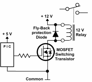
The 7805 gets too hot to touch when running with only one relay closed, so I definitely need to add an external source to the relay module. I'm assuming I can connect the external power source to the 3-pin connector using the JDVcc and Gnd pins?
Does anyone know if it needs to be +5V? Can I supply the relay board with 12V?
Another thing I don't understand is the fact that when the OVMS output port i low (0) the relay closes. When I set the output port to 1 the relay opens.
Looking at the closeup of the relay module, do I need to supply the Vcc pin with +5V on the 4-pin connector?
Regards,
Olav
Fra: ovmsdev-bounces@lists.teslaclub.hk [mailto:ovmsdev-bounces@lists.teslaclub.hk] På vegne av Thomas Bergo Sendt: 18. juni 2014 04:16 Til: OVMS Developers Emne: Re: [Ovmsdev] OVMS - HW
Hi Olav
Why don't do it easy and use a MOSFET and a 12V relay. Then you don't need to worry about heat and 5V power consumption.
See attached picture sample circuit. You should probably also add a resistor from the output of the PIC to GND to make sure the relay is turn properly off.
Regards, Thomas
2014-06-17 10:04 GMT+02:00 Olav A. Antonsen <olav@ansit.no>:
Seems like most car phone chargers uses a MC34063 switchmode-regulator chip that is much more efficient than a 7805. Will strip one out of its casing and give it a try.
For stronger currents I was told to use a UBEC.
--Olav
From: ovmsdev-bounces@lists.teslaclub.hk [mailto:ovmsdev-bounces@lists.teslaclub.hk] On Behalf Of Mastro Gippo Sent: 17. juni 2014 09:38
To: OVMS Developers Subject: Re: [Ovmsdev] OVMS - HW
Olav, the temperature should not raise that much, as the PCB is dissipating some of the heat. You can just try it and see if it heats up too much (being careful not to blow the fuse, as Mark said), or use your own 7805 slapped to a small heatsink. If you need more power, a car phone charger may be a better choice as it has a more efficient switching supply.
MG
2014-06-17 8:44 GMT+02:00 Olav A. Antonsen <olav@ansit.no>:
100°C/W! 9V * 0.2A = 1.8W => I need to keep the relays closed for 1 hour so it’s going to overheat!
Need to find another solution for feeding the relay module with +5V.
Mastro, any suggestions?
--Olav
From: ovmsdev-bounces@lists.teslaclub.hk [mailto:ovmsdev-bounces@lists.teslaclub.hk] On Behalf Of Mastro Gippo Sent: 17. juni 2014 00:33 To: OVMS Developers Subject: Re: [Ovmsdev] OVMS - HW
Hi, this is the correct DS: http://www.st.com/web/en/resource/technical/document/datasheet/CD00000444.pd...
for the DPAK package the OVMS is using, you have 8°C/W for the TJ and 100°C/W for TA. (it's a small package!)
Also, you must calc the dissipation thinking about the "dissipated" voltage, so not 5V but (14V-5V) = 9V (worst case).
You should also add some margin, e.g. use 100mA instead of 80mA just to be safe.
Just try it and keep a finger on the IC for a few minutes to see if it overheats, it shouldn't hurt the board.
MG
2014-06-17 0:14 GMT+02:00 Olav A. Antonsen <olav@ansit.no>:
Great video thermal design.
My knowledge on thermal design is only 30 minutes old, but my interpretation of the datasheet gives med
The regulator will reach 23°C/W above ambient.
Running at max 1.5A @ 5V = 7.5W.
23C/W => 172.5°C -> To hot to handle
2 relays @ 80mA each ~ 0.16A @ 5V ~ 0,8W ~ 18.4°C above ambient.
My conclusion is that adding a consumption of 160mA will raise the temperature 18.4°C above ambient. (This comes in addition to the current the OVMS module consumes.
)
Is this correct?
Regards
Olav
Fra: ovmsdev-bounces@lists.teslaclub.hk [mailto:ovmsdev-bounces@lists.teslaclub.hk] På vegne av Mastro Gippo Sendt: 16. juni 2014 23:38
Til: OVMS Developers Emne: Re: [Ovmsdev] OVMS - HW
The 1.5A is not the whole story; you can watch this: https://www.youtube.com/watch?v=8ruFVmxf0zs
Basically, if you had that 7805 on free air powering your two relays, it would (try to) reach about 170°C above ambient temperature. The PCB is a nice heatsink, but it is shared with the big GSM regulator, and that rises the temperature too.
By all means, experiment!! The 7805 has thermal protection, and you should test your circuit on the bench keeping a finger on the IC to feel if it gets too hot.
You should take care of the increased ripple too, but a small cap should do the trick there.
Regards
MG
2014-06-16 23:09 GMT+02:00 Olav A. Antonsen <olav@ansit.no>:
I got some help from a user on a Norwegian forum who pointed me to
<https://raw.githubusercontent.com/openvehicles/Open-Vehicle-Monitoring-System/master/vehicle/Car%20Module/v2-base/OVMS_V6A.pdf> https://raw.githubusercontent.com/openvehicles/Open-Vehicle-Monitoring-Syste...
Looks like a 7805-regulator is supplying the OVMS module with +5V @ 1.5A max.
https://www.sparkfun.com/datasheets/Components/LM7805.pdf
80mA won't be a problem then.
--Olav
Fra: ovmsdev-bounces@lists.teslaclub.hk [mailto:ovmsdev-bounces@lists.teslaclub.hk] På vegne av Mastro Gippo Sendt: 16. juni 2014 23:03 Til: OVMS Developers Emne: Re: [Ovmsdev] OVMS - HW
It may be a problem to get the 5V from the output of the regulator, but the nice thing about that module is that it is isolated; you can connect your own power supply and be 100% safe. These relays draw about 80mA each (just tested them, I have the same product at home), so if you turn them on one at a time and for short periods of time it should be ok (I don't know a lot about the termal design of the OVMS).
MG
2014-06-16 22:37 GMT+02:00 Olav A. Antonsen <olav@ansit.no>:
Hello
My knowledge of electronics is limited.
As far as I understand the OVMS module is supplied with +12V via the OBD connector. What I don't understand is where the +5V comes from?
https://github.com/openvehicles/Open-Vehicle-Monitoring-System/blob/master/v...
I'm currently trying to control a relay using the RC3 output on the PIC18F2580 as a control signal to a rely on a relay module
http://www.dx.com/p/arduino-2-channel-relay-shield-module-red-144140#.U59Qav....
The relay module needs to be supplied with +5V to drive the relays, and my plan was to get the +5V from the OVMS module using pin 13 on the HEADER 9X2.
But I'm afraid I might blow something on the OVMS module if the relay module draws to many mA.
Any advice would be appreciated.
--Olav
OvmsDev mailing list OvmsDev@lists.teslaclub.hk http://lists.teslaclub.hk/mailman/listinfo/ovmsdev
OvmsDev mailing list OvmsDev@lists.teslaclub.hk http://lists.teslaclub.hk/mailman/listinfo/ovmsdev
OvmsDev mailing list OvmsDev@lists.teslaclub.hk http://lists.teslaclub.hk/mailman/listinfo/ovmsdev
OvmsDev mailing list OvmsDev@lists.teslaclub.hk http://lists.teslaclub.hk/mailman/listinfo/ovmsdev
OvmsDev mailing list OvmsDev@lists.teslaclub.hk http://lists.teslaclub.hk/mailman/listinfo/ovmsdev
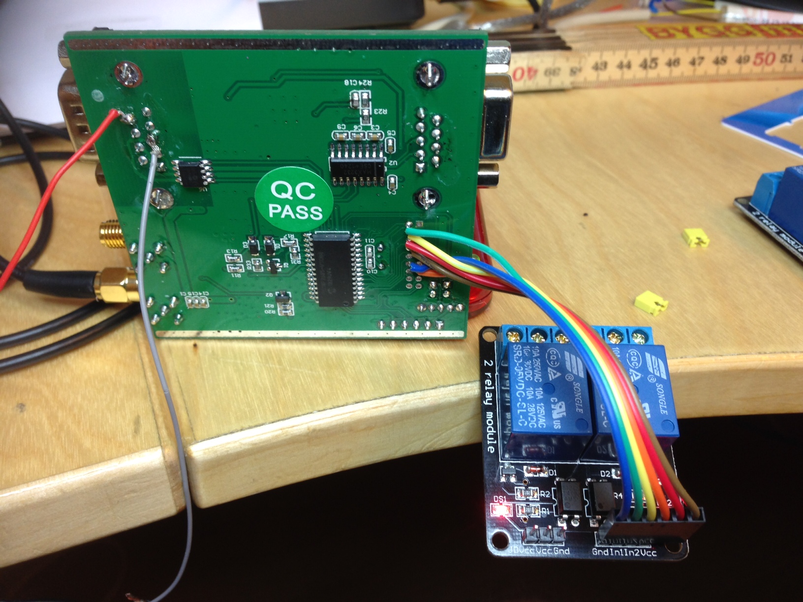
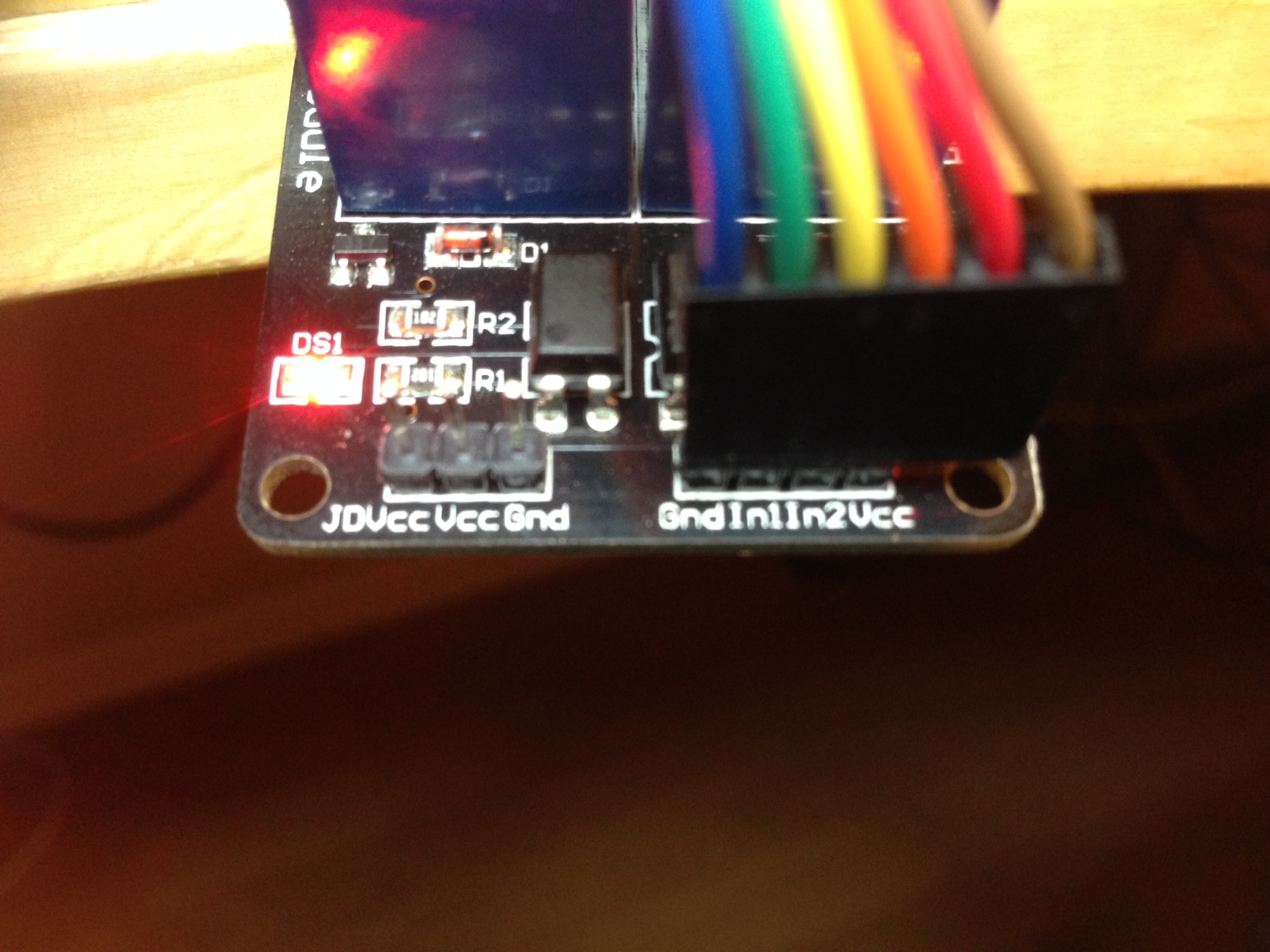
Found the answer to one of my questions...
The relays pins are active low.
http://arduino-info.wikispaces.com/ArduinoPower#OI
Fra: ovmsdev-bounces@lists.teslaclub.hk [mailto:ovmsdev-bounces@lists.teslaclub.hk] På vegne av Olav A. Antonsen Sendt: 26. juni 2014 01:55 Til: 'OVMS Developers' Emne: Re: [Ovmsdev] OVMS - HW
The 7805 gets too hot to touch when running with only one relay closed, so I definitely need to add an external source to the relay module. I'm assuming I can connect the external power source to the 3-pin connector using the JDVcc and Gnd pins?
Does anyone know if it needs to be +5V? Can I supply the relay board with 12V?
Another thing I don't understand is the fact that when the OVMS output port i low (0) the relay closes. When I set the output port to 1 the relay opens.
Looking at the closeup of the relay module, do I need to supply the Vcc pin with +5V on the 4-pin connector?
Regards,
Olav
Fra: ovmsdev-bounces@lists.teslaclub.hk [mailto:ovmsdev-bounces@lists.teslaclub.hk] På vegne av Thomas Bergo Sendt: 18. juni 2014 04:16 Til: OVMS Developers Emne: Re: [Ovmsdev] OVMS - HW
Hi Olav
Why don't do it easy and use a MOSFET and a 12V relay. Then you don't need to worry about heat and 5V power consumption.
See attached picture sample circuit. You should probably also add a resistor from the output of the PIC to GND to make sure the relay is turn properly off.
Regards, Thomas
2014-06-17 10:04 GMT+02:00 Olav A. Antonsen <olav@ansit.no>:
Seems like most car phone chargers uses a MC34063 switchmode-regulator chip that is much more efficient than a 7805. Will strip one out of its casing and give it a try.
For stronger currents I was told to use a UBEC.
--Olav
From: ovmsdev-bounces@lists.teslaclub.hk [mailto:ovmsdev-bounces@lists.teslaclub.hk] On Behalf Of Mastro Gippo Sent: 17. juni 2014 09:38
To: OVMS Developers Subject: Re: [Ovmsdev] OVMS - HW
Olav, the temperature should not raise that much, as the PCB is dissipating some of the heat. You can just try it and see if it heats up too much (being careful not to blow the fuse, as Mark said), or use your own 7805 slapped to a small heatsink. If you need more power, a car phone charger may be a better choice as it has a more efficient switching supply.
MG
2014-06-17 8:44 GMT+02:00 Olav A. Antonsen <olav@ansit.no>:
100°C/W! 9V * 0.2A = 1.8W => I need to keep the relays closed for 1 hour so it’s going to overheat!
Need to find another solution for feeding the relay module with +5V.
Mastro, any suggestions?
--Olav
From: ovmsdev-bounces@lists.teslaclub.hk [mailto:ovmsdev-bounces@lists.teslaclub.hk] On Behalf Of Mastro Gippo Sent: 17. juni 2014 00:33 To: OVMS Developers Subject: Re: [Ovmsdev] OVMS - HW
Hi, this is the correct DS: http://www.st.com/web/en/resource/technical/document/datasheet/CD00000444.pd...
for the DPAK package the OVMS is using, you have 8°C/W for the TJ and 100°C/W for TA. (it's a small package!)
Also, you must calc the dissipation thinking about the "dissipated" voltage, so not 5V but (14V-5V) = 9V (worst case).
You should also add some margin, e.g. use 100mA instead of 80mA just to be safe.
Just try it and keep a finger on the IC for a few minutes to see if it overheats, it shouldn't hurt the board.
MG
2014-06-17 0:14 GMT+02:00 Olav A. Antonsen <olav@ansit.no>:
Great video thermal design.
My knowledge on thermal design is only 30 minutes old, but my interpretation of the datasheet gives med
The regulator will reach 23°C/W above ambient.
Running at max 1.5A @ 5V = 7.5W.
23C/W => 172.5°C -> To hot to handle
2 relays @ 80mA each ~ 0.16A @ 5V ~ 0,8W ~ 18.4°C above ambient.
My conclusion is that adding a consumption of 160mA will raise the temperature 18.4°C above ambient. (This comes in addition to the current the OVMS module consumes.
)
Is this correct?
Regards
Olav
Fra: ovmsdev-bounces@lists.teslaclub.hk [mailto:ovmsdev-bounces@lists.teslaclub.hk] På vegne av Mastro Gippo Sendt: 16. juni 2014 23:38
Til: OVMS Developers Emne: Re: [Ovmsdev] OVMS - HW
The 1.5A is not the whole story; you can watch this: https://www.youtube.com/watch?v=8ruFVmxf0zs
Basically, if you had that 7805 on free air powering your two relays, it would (try to) reach about 170°C above ambient temperature. The PCB is a nice heatsink, but it is shared with the big GSM regulator, and that rises the temperature too.
By all means, experiment!! The 7805 has thermal protection, and you should test your circuit on the bench keeping a finger on the IC to feel if it gets too hot.
You should take care of the increased ripple too, but a small cap should do the trick there.
Regards
MG
2014-06-16 23:09 GMT+02:00 Olav A. Antonsen <olav@ansit.no>:
I got some help from a user on a Norwegian forum who pointed me to
<https://raw.githubusercontent.com/openvehicles/Open-Vehicle-Monitoring-System/master/vehicle/Car%20Module/v2-base/OVMS_V6A.pdf> https://raw.githubusercontent.com/openvehicles/Open-Vehicle-Monitoring-Syste...
Looks like a 7805-regulator is supplying the OVMS module with +5V @ 1.5A max.
https://www.sparkfun.com/datasheets/Components/LM7805.pdf
80mA won't be a problem then.
--Olav
Fra: ovmsdev-bounces@lists.teslaclub.hk [mailto:ovmsdev-bounces@lists.teslaclub.hk] På vegne av Mastro Gippo Sendt: 16. juni 2014 23:03 Til: OVMS Developers Emne: Re: [Ovmsdev] OVMS - HW
It may be a problem to get the 5V from the output of the regulator, but the nice thing about that module is that it is isolated; you can connect your own power supply and be 100% safe. These relays draw about 80mA each (just tested them, I have the same product at home), so if you turn them on one at a time and for short periods of time it should be ok (I don't know a lot about the termal design of the OVMS).
MG
2014-06-16 22:37 GMT+02:00 Olav A. Antonsen <olav@ansit.no>:
Hello
My knowledge of electronics is limited.
As far as I understand the OVMS module is supplied with +12V via the OBD connector. What I don't understand is where the +5V comes from?
https://github.com/openvehicles/Open-Vehicle-Monitoring-System/blob/master/v...
I'm currently trying to control a relay using the RC3 output on the PIC18F2580 as a control signal to a rely on a relay module
http://www.dx.com/p/arduino-2-channel-relay-shield-module-red-144140#.U59Qav....
The relay module needs to be supplied with +5V to drive the relays, and my plan was to get the +5V from the OVMS module using pin 13 on the HEADER 9X2.
But I'm afraid I might blow something on the OVMS module if the relay module draws to many mA.
Any advice would be appreciated.
--Olav
OvmsDev mailing list OvmsDev@lists.teslaclub.hk http://lists.teslaclub.hk/mailman/listinfo/ovmsdev
OvmsDev mailing list OvmsDev@lists.teslaclub.hk http://lists.teslaclub.hk/mailman/listinfo/ovmsdev
OvmsDev mailing list OvmsDev@lists.teslaclub.hk http://lists.teslaclub.hk/mailman/listinfo/ovmsdev
OvmsDev mailing list OvmsDev@lists.teslaclub.hk http://lists.teslaclub.hk/mailman/listinfo/ovmsdev
OvmsDev mailing list OvmsDev@lists.teslaclub.hk http://lists.teslaclub.hk/mailman/listinfo/ovmsdev
You need a datasheet, or trace the wiring.
Seems to be fasttech have the same board slightly cheaper:
http://www.fasttech.com/products/0/10000007/1144100-ac-dc-2-channel-relay-mo...
and the reviews there say that the relay side must be powered by 12V. There is a jumper on the board.
If you don't have datasheet, perhaps best is to trace the circuit (it is not complex). Best would be for you to power the opto-isolator side from 5V OVMS, and the relays from 12V direct.
Regards, Mark.
On 26 Jun, 2014, at 8:06 am, Olav A. Antonsen <olav@ansit.no> wrote:
Found the answer to one of my questions...
The relays pins are active low.
http://arduino-info.wikispaces.com/ArduinoPower#OI
Fra: ovmsdev-bounces@lists.teslaclub.hk [mailto:ovmsdev-bounces@lists.teslaclub.hk] På vegne av Olav A. Antonsen Sendt: 26. juni 2014 01:55 Til: 'OVMS Developers' Emne: Re: [Ovmsdev] OVMS - HW
The 7805 gets too hot to touch when running with only one relay closed, so I definitely need to add an external source to the relay module. I'm assuming I can connect the external power source to the 3-pin connector using the JDVcc and Gnd pins?
Does anyone know if it needs to be +5V? Can I supply the relay board with 12V?
Another thing I don't understand is the fact that when the OVMS output port i low (0) the relay closes. When I set the output port to 1 the relay opens.
Looking at the closeup of the relay module, do I need to supply the Vcc pin with +5V on the 4-pin connector?
Regards, Olav
Fra: ovmsdev-bounces@lists.teslaclub.hk [mailto:ovmsdev-bounces@lists.teslaclub.hk] På vegne av Thomas Bergo Sendt: 18. juni 2014 04:16 Til: OVMS Developers Emne: Re: [Ovmsdev] OVMS - HW
Hi Olav
Why don't do it easy and use a MOSFET and a 12V relay. Then you don't need to worry about heat and 5V power consumption. See attached picture sample circuit. You should probably also add a resistor from the output of the PIC to GND to make sure the relay is turn properly off.
Regards, Thomas
2014-06-17 10:04 GMT+02:00 Olav A. Antonsen <olav@ansit.no>: Seems like most car phone chargers uses a MC34063 switchmode-regulator chip that is much more efficient than a 7805. Will strip one out of its casing and give it a try.
For stronger currents I was told to use a UBEC.
--Olav From: ovmsdev-bounces@lists.teslaclub.hk [mailto:ovmsdev-bounces@lists.teslaclub.hk] On Behalf Of Mastro Gippo Sent: 17. juni 2014 09:38
To: OVMS Developers Subject: Re: [Ovmsdev] OVMS - HW
Olav, the temperature should not raise that much, as the PCB is dissipating some of the heat. You can just try it and see if it heats up too much (being careful not to blow the fuse, as Mark said), or use your own 7805 slapped to a small heatsink. If you need more power, a car phone charger may be a better choice as it has a more efficient switching supply. MG
2014-06-17 8:44 GMT+02:00 Olav A. Antonsen <olav@ansit.no>: 100°C/W! 9V * 0.2A = 1.8W => I need to keep the relays closed for 1 hour so it’s going to overheat!
Need to find another solution for feeding the relay module with +5V.
Mastro, any suggestions?
--Olav
From: ovmsdev-bounces@lists.teslaclub.hk [mailto:ovmsdev-bounces@lists.teslaclub.hk] On Behalf Of Mastro Gippo Sent: 17. juni 2014 00:33 To: OVMS Developers Subject: Re: [Ovmsdev] OVMS - HW
Hi, this is the correct DS: http://www.st.com/web/en/resource/technical/document/datasheet/CD00000444.pd... for the DPAK package the OVMS is using, you have 8°C/W for the TJ and 100°C/W for TA. (it's a small package!) Also, you must calc the dissipation thinking about the "dissipated" voltage, so not 5V but (14V-5V) = 9V (worst case). You should also add some margin, e.g. use 100mA instead of 80mA just to be safe. Just try it and keep a finger on the IC for a few minutes to see if it overheats, it shouldn't hurt the board.
MG
2014-06-17 0:14 GMT+02:00 Olav A. Antonsen <olav@ansit.no>: Great video thermal design.
My knowledge on thermal design is only 30 minutes old, but my interpretation of the datasheet gives med
The regulator will reach 23°C/W above ambient.
Running at max 1.5A @ 5V = 7.5W.
23C/W => 172.5°C -> To hot to handle
2 relays @ 80mA each ~ 0.16A @ 5V ~ 0,8W ~ 18.4°C above ambient.
My conclusion is that adding a consumption of 160mA will raise the temperature 18.4°C above ambient. (This comes in addition to the current the OVMS module consumes. )
Is this correct?
Regards Olav
Fra: ovmsdev-bounces@lists.teslaclub.hk [mailto:ovmsdev-bounces@lists.teslaclub.hk] På vegne av Mastro Gippo Sendt: 16. juni 2014 23:38
Til: OVMS Developers Emne: Re: [Ovmsdev] OVMS - HW
The 1.5A is not the whole story; you can watch this: https://www.youtube.com/watch?v=8ruFVmxf0zs Basically, if you had that 7805 on free air powering your two relays, it would (try to) reach about 170°C above ambient temperature. The PCB is a nice heatsink, but it is shared with the big GSM regulator, and that rises the temperature too. By all means, experiment!! The 7805 has thermal protection, and you should test your circuit on the bench keeping a finger on the IC to feel if it gets too hot. You should take care of the increased ripple too, but a small cap should do the trick there.
Regards MG
2014-06-16 23:09 GMT+02:00 Olav A. Antonsen <olav@ansit.no>: I got some help from a user on a Norwegian forum who pointed me to
https://raw.githubusercontent.com/openvehicles/Open-Vehicle-Monitoring-Syste...
Looks like a 7805-regulator is supplying the OVMS module with +5V @ 1.5A max.
https://www.sparkfun.com/datasheets/Components/LM7805.pdf
80mA won't be a problem then.
--Olav
Fra: ovmsdev-bounces@lists.teslaclub.hk [mailto:ovmsdev-bounces@lists.teslaclub.hk] På vegne av Mastro Gippo Sendt: 16. juni 2014 23:03 Til: OVMS Developers Emne: Re: [Ovmsdev] OVMS - HW
It may be a problem to get the 5V from the output of the regulator, but the nice thing about that module is that it is isolated; you can connect your own power supply and be 100% safe. These relays draw about 80mA each (just tested them, I have the same product at home), so if you turn them on one at a time and for short periods of time it should be ok (I don't know a lot about the termal design of the OVMS). MG
2014-06-16 22:37 GMT+02:00 Olav A. Antonsen <olav@ansit.no>: Hello
My knowledge of electronics is limited.
As far as I understand the OVMS module is supplied with +12V via the OBD connector. What I don't understand is where the +5V comes from?
https://github.com/openvehicles/Open-Vehicle-Monitoring-System/blob/master/v...
I'm currently trying to control a relay using the RC3 output on the PIC18F2580 as a control signal to a rely on a relay module
http://www.dx.com/p/arduino-2-channel-relay-shield-module-red-144140#.U59Qav....
The relay module needs to be supplied with +5V to drive the relays, and my plan was to get the +5V from the OVMS module using pin 13 on the HEADER 9X2.
But I'm afraid I might blow something on the OVMS module if the relay module draws to many mA.
Any advice would be appreciated.
--Olav
OvmsDev mailing list OvmsDev@lists.teslaclub.hk http://lists.teslaclub.hk/mailman/listinfo/ovmsdev
OvmsDev mailing list OvmsDev@lists.teslaclub.hk http://lists.teslaclub.hk/mailman/listinfo/ovmsdev
OvmsDev mailing list OvmsDev@lists.teslaclub.hk http://lists.teslaclub.hk/mailman/listinfo/ovmsdev
OvmsDev mailing list OvmsDev@lists.teslaclub.hk http://lists.teslaclub.hk/mailman/listinfo/ovmsdev
OvmsDev mailing list OvmsDev@lists.teslaclub.hk http://lists.teslaclub.hk/mailman/listinfo/ovmsdev
OvmsDev mailing list OvmsDev@lists.teslaclub.hk http://lists.teslaclub.hk/mailman/listinfo/ovmsdev
This may help:
http://www.hobbytronics.co.uk/8-channel-relay-board
Seems similar and suggests you put 12V on VCC and that the green jumper is to isolate signal ground from power ground. In OVMS case, the two grounds are the same so it shouldn't matter.
Regards, Mark.
On 26 Jun, 2014, at 8:36 am, Mark Webb-Johnson <mark@webb-johnson.net> wrote:
You need a datasheet, or trace the wiring.
Seems to be fasttech have the same board slightly cheaper:
http://www.fasttech.com/products/0/10000007/1144100-ac-dc-2-channel-relay-mo...
and the reviews there say that the relay side must be powered by 12V. There is a jumper on the board.
If you don't have datasheet, perhaps best is to trace the circuit (it is not complex). Best would be for you to power the opto-isolator side from 5V OVMS, and the relays from 12V direct.
Regards, Mark.
On 26 Jun, 2014, at 8:06 am, Olav A. Antonsen <olav@ansit.no> wrote:
Found the answer to one of my questions...
The relays pins are active low.
http://arduino-info.wikispaces.com/ArduinoPower#OI
Fra: ovmsdev-bounces@lists.teslaclub.hk [mailto:ovmsdev-bounces@lists.teslaclub.hk] På vegne av Olav A. Antonsen Sendt: 26. juni 2014 01:55 Til: 'OVMS Developers' Emne: Re: [Ovmsdev] OVMS - HW
The 7805 gets too hot to touch when running with only one relay closed, so I definitely need to add an external source to the relay module. I'm assuming I can connect the external power source to the 3-pin connector using the JDVcc and Gnd pins?
Does anyone know if it needs to be +5V? Can I supply the relay board with 12V?
Another thing I don't understand is the fact that when the OVMS output port i low (0) the relay closes. When I set the output port to 1 the relay opens.
Looking at the closeup of the relay module, do I need to supply the Vcc pin with +5V on the 4-pin connector?
Regards, Olav
Fra: ovmsdev-bounces@lists.teslaclub.hk [mailto:ovmsdev-bounces@lists.teslaclub.hk] På vegne av Thomas Bergo Sendt: 18. juni 2014 04:16 Til: OVMS Developers Emne: Re: [Ovmsdev] OVMS - HW
Hi Olav
Why don't do it easy and use a MOSFET and a 12V relay. Then you don't need to worry about heat and 5V power consumption. See attached picture sample circuit. You should probably also add a resistor from the output of the PIC to GND to make sure the relay is turn properly off.
Regards, Thomas
2014-06-17 10:04 GMT+02:00 Olav A. Antonsen <olav@ansit.no>: Seems like most car phone chargers uses a MC34063 switchmode-regulator chip that is much more efficient than a 7805. Will strip one out of its casing and give it a try.
For stronger currents I was told to use a UBEC.
--Olav From: ovmsdev-bounces@lists.teslaclub.hk [mailto:ovmsdev-bounces@lists.teslaclub.hk] On Behalf Of Mastro Gippo Sent: 17. juni 2014 09:38
To: OVMS Developers Subject: Re: [Ovmsdev] OVMS - HW
Olav, the temperature should not raise that much, as the PCB is dissipating some of the heat. You can just try it and see if it heats up too much (being careful not to blow the fuse, as Mark said), or use your own 7805 slapped to a small heatsink. If you need more power, a car phone charger may be a better choice as it has a more efficient switching supply. MG
2014-06-17 8:44 GMT+02:00 Olav A. Antonsen <olav@ansit.no>: 100°C/W! 9V * 0.2A = 1.8W => I need to keep the relays closed for 1 hour so it’s going to overheat!
Need to find another solution for feeding the relay module with +5V.
Mastro, any suggestions?
--Olav
From: ovmsdev-bounces@lists.teslaclub.hk [mailto:ovmsdev-bounces@lists.teslaclub.hk] On Behalf Of Mastro Gippo Sent: 17. juni 2014 00:33 To: OVMS Developers Subject: Re: [Ovmsdev] OVMS - HW
Hi, this is the correct DS: http://www.st.com/web/en/resource/technical/document/datasheet/CD00000444.pd... for the DPAK package the OVMS is using, you have 8°C/W for the TJ and 100°C/W for TA. (it's a small package!) Also, you must calc the dissipation thinking about the "dissipated" voltage, so not 5V but (14V-5V) = 9V (worst case). You should also add some margin, e.g. use 100mA instead of 80mA just to be safe. Just try it and keep a finger on the IC for a few minutes to see if it overheats, it shouldn't hurt the board.
MG
2014-06-17 0:14 GMT+02:00 Olav A. Antonsen <olav@ansit.no>: Great video thermal design.
My knowledge on thermal design is only 30 minutes old, but my interpretation of the datasheet gives med
The regulator will reach 23°C/W above ambient.
Running at max 1.5A @ 5V = 7.5W.
23C/W => 172.5°C -> To hot to handle
2 relays @ 80mA each ~ 0.16A @ 5V ~ 0,8W ~ 18.4°C above ambient.
My conclusion is that adding a consumption of 160mA will raise the temperature 18.4°C above ambient. (This comes in addition to the current the OVMS module consumes. )
Is this correct?
Regards Olav
Fra: ovmsdev-bounces@lists.teslaclub.hk [mailto:ovmsdev-bounces@lists.teslaclub.hk] På vegne av Mastro Gippo Sendt: 16. juni 2014 23:38
Til: OVMS Developers Emne: Re: [Ovmsdev] OVMS - HW
The 1.5A is not the whole story; you can watch this: https://www.youtube.com/watch?v=8ruFVmxf0zs Basically, if you had that 7805 on free air powering your two relays, it would (try to) reach about 170°C above ambient temperature. The PCB is a nice heatsink, but it is shared with the big GSM regulator, and that rises the temperature too. By all means, experiment!! The 7805 has thermal protection, and you should test your circuit on the bench keeping a finger on the IC to feel if it gets too hot. You should take care of the increased ripple too, but a small cap should do the trick there.
Regards MG
2014-06-16 23:09 GMT+02:00 Olav A. Antonsen <olav@ansit.no>: I got some help from a user on a Norwegian forum who pointed me to
https://raw.githubusercontent.com/openvehicles/Open-Vehicle-Monitoring-Syste...
Looks like a 7805-regulator is supplying the OVMS module with +5V @ 1.5A max.
https://www.sparkfun.com/datasheets/Components/LM7805.pdf
80mA won't be a problem then.
--Olav
Fra: ovmsdev-bounces@lists.teslaclub.hk [mailto:ovmsdev-bounces@lists.teslaclub.hk] På vegne av Mastro Gippo Sendt: 16. juni 2014 23:03 Til: OVMS Developers Emne: Re: [Ovmsdev] OVMS - HW
It may be a problem to get the 5V from the output of the regulator, but the nice thing about that module is that it is isolated; you can connect your own power supply and be 100% safe. These relays draw about 80mA each (just tested them, I have the same product at home), so if you turn them on one at a time and for short periods of time it should be ok (I don't know a lot about the termal design of the OVMS). MG
2014-06-16 22:37 GMT+02:00 Olav A. Antonsen <olav@ansit.no>: Hello
My knowledge of electronics is limited.
As far as I understand the OVMS module is supplied with +12V via the OBD connector. What I don't understand is where the +5V comes from?
https://github.com/openvehicles/Open-Vehicle-Monitoring-System/blob/master/v...
I'm currently trying to control a relay using the RC3 output on the PIC18F2580 as a control signal to a rely on a relay module
http://www.dx.com/p/arduino-2-channel-relay-shield-module-red-144140#.U59Qav....
The relay module needs to be supplied with +5V to drive the relays, and my plan was to get the +5V from the OVMS module using pin 13 on the HEADER 9X2.
But I'm afraid I might blow something on the OVMS module if the relay module draws to many mA.
Any advice would be appreciated.
--Olav
OvmsDev mailing list OvmsDev@lists.teslaclub.hk http://lists.teslaclub.hk/mailman/listinfo/ovmsdev
OvmsDev mailing list OvmsDev@lists.teslaclub.hk http://lists.teslaclub.hk/mailman/listinfo/ovmsdev
OvmsDev mailing list OvmsDev@lists.teslaclub.hk http://lists.teslaclub.hk/mailman/listinfo/ovmsdev
OvmsDev mailing list OvmsDev@lists.teslaclub.hk http://lists.teslaclub.hk/mailman/listinfo/ovmsdev
OvmsDev mailing list OvmsDev@lists.teslaclub.hk http://lists.teslaclub.hk/mailman/listinfo/ovmsdev
OvmsDev mailing list OvmsDev@lists.teslaclub.hk http://lists.teslaclub.hk/mailman/listinfo/ovmsdev
OvmsDev mailing list OvmsDev@lists.teslaclub.hk http://lists.teslaclub.hk/mailman/listinfo/ovmsdev
Be careful and read the relay code, dx ones seem to be 5v as mine, while fasttech one is 12v. I don't have the relay now, but you should have no problem supplying it from the secondary connector, just don't feed it back to the ovms. The board already provides optocouplers and mosfets to drive the relay, so you should just need to pull signals to ground. Regards MG On 26 Jun 2014 02:43, "Mark Webb-Johnson" <mark@webb-johnson.net> wrote:
This may help:
http://www.hobbytronics.co.uk/8-channel-relay-board
Seems similar and suggests you put 12V on VCC and that the green jumper is to isolate signal ground from power ground. In OVMS case, the two grounds are the same so it shouldn't matter.
Regards, Mark.
On 26 Jun, 2014, at 8:36 am, Mark Webb-Johnson <mark@webb-johnson.net> wrote:
You need a datasheet, or trace the wiring.
Seems to be fasttech have the same board slightly cheaper:
http://www.fasttech.com/products/0/10000007/1144100-ac-dc-2-channel-relay-mo...
and the reviews there say that the relay side must be powered by 12V. There is a jumper on the board.
If you don't have datasheet, perhaps best is to trace the circuit (it is not complex). Best would be for you to power the opto-isolator side from 5V OVMS, and the relays from 12V direct.
Regards, Mark.
On 26 Jun, 2014, at 8:06 am, Olav A. Antonsen <olav@ansit.no> wrote:
Found the answer to one of my questions...
The relays pins are active low.
http://arduino-info.wikispaces.com/ArduinoPower#OI
*Fra:* ovmsdev-bounces@lists.teslaclub.hk [ mailto:ovmsdev-bounces@lists.teslaclub.hk <ovmsdev-bounces@lists.teslaclub.hk>] *På vegne av* Olav A. Antonsen *Sendt:* 26. juni 2014 01:55 *Til:* 'OVMS Developers' *Emne:* Re: [Ovmsdev] OVMS - HW
The 7805 gets too hot to touch when running with only one relay closed, so I definitely need to add an external source to the relay module. I'm assuming I can connect the external power source to the 3-pin connector using the JDVcc and Gnd pins?
Does anyone know if it needs to be +5V? Can I supply the relay board with 12V?
Another thing I don't understand is the fact that when the OVMS output port i low (0) the relay closes. When I set the output port to 1 the relay opens.
Looking at the closeup of the relay module, do I need to supply the Vcc pin with +5V on the 4-pin connector?
Regards, Olav
*Fra:* ovmsdev-bounces@lists.teslaclub.hk [ mailto:ovmsdev-bounces@lists.teslaclub.hk <ovmsdev-bounces@lists.teslaclub.hk>] *På vegne av* Thomas Bergo *Sendt:* 18. juni 2014 04:16 *Til:* OVMS Developers *Emne:* Re: [Ovmsdev] OVMS - HW
Hi Olav
Why don't do it easy and use a MOSFET and a 12V relay. Then you don't need to worry about heat and 5V power consumption. See attached picture sample circuit. You should probably also add a resistor from the output of the PIC to GND to make sure the relay is turn properly off.
Regards, Thomas
2014-06-17 10:04 GMT+02:00 Olav A. Antonsen <olav@ansit.no>: Seems like most car phone chargers uses a MC34063 switchmode-regulator chip that is much more efficient than a 7805. Will strip one out of its casing and give it a try.
For stronger currents I was told to use a UBEC.
--Olav *From:* ovmsdev-bounces@lists.teslaclub.hk [mailto: ovmsdev-bounces@lists.teslaclub.hk] *On Behalf Of *Mastro Gippo *Sent:* 17. juni 2014 09:38
*To:* OVMS Developers *Subject:* Re: [Ovmsdev] OVMS - HW
Olav, the temperature should not raise that much, as the PCB is dissipating some of the heat. You can just try it and see if it heats up too much (being careful not to blow the fuse, as Mark said), or use your own 7805 slapped to a small heatsink. If you need more power, a car phone charger may be a better choice as it has a more efficient switching supply. MG
2014-06-17 8:44 GMT+02:00 Olav A. Antonsen <olav@ansit.no>:
100°C/W! 9V * 0.2A = 1.8W => I need to keep the relays closed for 1 hour so it’s going to overheat!
Need to find another solution for feeding the relay module with +5V.
Mastro, any suggestions?
--Olav
*From:* ovmsdev-bounces@lists.teslaclub.hk [mailto: ovmsdev-bounces@lists.teslaclub.hk] *On Behalf Of *Mastro Gippo *Sent:* 17. juni 2014 00:33 *To:* OVMS Developers *Subject:* Re: [Ovmsdev] OVMS - HW
Hi, this is the correct DS: http://www.st.com/web/en/resource/technical/document/datasheet/CD00000444.pd... for the DPAK package the OVMS is using, you have 8°C/W for the TJ and 100°C/W for TA. (it's a small package!) Also, you must calc the dissipation thinking about the "dissipated" voltage, so not 5V but (14V-5V) = 9V (worst case). You should also add some margin, e.g. use 100mA instead of 80mA just to be safe. Just try it and keep a finger on the IC for a few minutes to see if it overheats, it shouldn't hurt the board.
MG
2014-06-17 0:14 GMT+02:00 Olav A. Antonsen <olav@ansit.no>:
Great video thermal design.
My knowledge on thermal design is only 30 minutes old, but my interpretation of the datasheet gives med
The regulator will reach 23°C/W above ambient.
Running at max 1.5A @ 5V = 7.5W.
23C/W => 172.5°C -> To hot to handle
2 relays @ 80mA each ~ 0.16A @ 5V ~ 0,8W ~ 18.4°C above ambient.
My conclusion is that adding a consumption of 160mA will raise the temperature 18.4°C above ambient. (This comes in addition to the current the OVMS module consumes. )
Is this correct?
Regards Olav
*Fra:* ovmsdev-bounces@lists.teslaclub.hk [mailto: ovmsdev-bounces@lists.teslaclub.hk] *På vegne av* Mastro Gippo *Sendt:* 16. juni 2014 23:38
*Til:* OVMS Developers *Emne:* Re: [Ovmsdev] OVMS - HW
The 1.5A is not the whole story; you can watch this: https://www.youtube.com/watch?v=8ruFVmxf0zs Basically, if you had that 7805 on free air powering your two relays, it would (try to) reach about 170°C above ambient temperature. The PCB is a nice heatsink, but it is shared with the big GSM regulator, and that rises the temperature too. By all means, experiment!! The 7805 has thermal protection, and you should test your circuit on the bench keeping a finger on the IC to feel if it gets too hot.
You should take care of the increased ripple too, but a small cap should do the trick there. Regards MG
2014-06-16 23:09 GMT+02:00 Olav A. Antonsen <olav@ansit.no>: I got some help from a user on a Norwegian forum who pointed me to
https://raw.githubusercontent.com/openvehicles/Open-Vehicle-Monitoring-Syste...
Looks like a 7805-regulator is supplying the OVMS module with +5V @ 1.5A max.
https://www.sparkfun.com/datasheets/Components/LM7805.pdf
80mA won't be a problem then.
--Olav
*Fra:* ovmsdev-bounces@lists.teslaclub.hk [mailto: ovmsdev-bounces@lists.teslaclub.hk] *På vegne av* Mastro Gippo *Sendt:* 16. juni 2014 23:03 *Til:* OVMS Developers *Emne:* Re: [Ovmsdev] OVMS - HW
It may be a problem to get the 5V from the output of the regulator, but the nice thing about that module is that it is isolated; you can connect your own power supply and be 100% safe. These relays draw about 80mA each (just tested them, I have the same product at home), so if you turn them on one at a time and for short periods of time it should be ok (I don't know a lot about the termal design of the OVMS). MG
2014-06-16 22:37 GMT+02:00 Olav A. Antonsen <olav@ansit.no>: Hello
My knowledge of electronics is limited.
As far as I understand the OVMS module is supplied with +12V via the OBD connector. What I don't understand is where the +5V comes from?
https://github.com/openvehicles/Open-Vehicle-Monitoring-System/blob/master/v...
I'm currently trying to control a relay using the RC3 output on the PIC18F2580 as a control signal to a rely on a relay module
http://www.dx.com/p/arduino-2-channel-relay-shield-module-red-144140#.U59Qav... .
The relay module needs to be supplied with +5V to drive the relays, and my plan was to get the +5V from the OVMS module using pin 13 on the HEADER 9X2.
But I'm afraid I might blow something on the OVMS module if the relay module draws to many mA.
Any advice would be appreciated.
--Olav
OvmsDev mailing list OvmsDev@lists.teslaclub.hk http://lists.teslaclub.hk/mailman/listinfo/ovmsdev
OvmsDev mailing list OvmsDev@lists.teslaclub.hk http://lists.teslaclub.hk/mailman/listinfo/ovmsdev
OvmsDev mailing list OvmsDev@lists.teslaclub.hk http://lists.teslaclub.hk/mailman/listinfo/ovmsdev
OvmsDev mailing list OvmsDev@lists.teslaclub.hk http://lists.teslaclub.hk/mailman/listinfo/ovmsdev
OvmsDev mailing list OvmsDev@lists.teslaclub.hk http://lists.teslaclub.hk/mailman/listinfo/ovmsdev
OvmsDev mailing list OvmsDev@lists.teslaclub.hk http://lists.teslaclub.hk/mailman/listinfo/ovmsdev
OvmsDev mailing list OvmsDev@lists.teslaclub.hk http://lists.teslaclub.hk/mailman/listinfo/ovmsdev
OvmsDev mailing list OvmsDev@lists.teslaclub.hk http://lists.teslaclub.hk/mailman/listinfo/ovmsdev
I found the data sheet for the relays, and it seems like they come in 3,5,6,9,12,24,48 V versions. (http://www.hobbytronics.co.uk/datasheets/songle-12v-relay.pdf).
The relay on my module is marked as SRD-05VDC-SL-C meaning the coil should be driven by +5V.
Question1
If I get a relay module with 12V coils can I use the +12V pin on the 9X2 header (OVMS) module as a source for 12V? Any fuses I can risk blowing?
Question2
Instead of soldering wires directly to the 9x2 header on the OVMS, is the any other way to connect wires? I’m thinking about something similar to the connector (pins) used to connect the PIC programmer to the OVMS?
Regards
Olav
From: ovmsdev-bounces@lists.teslaclub.hk [mailto:ovmsdev-bounces@lists.teslaclub.hk] On Behalf Of Mastro Gippo Sent: 26. juni 2014 09:21 To: OVMS Developers Subject: Re: [Ovmsdev] OVMS - HW
Be careful and read the relay code, dx ones seem to be 5v as mine, while fasttech one is 12v. I don't have the relay now, but you should have no problem supplying it from the secondary connector, just don't feed it back to the ovms. The board already provides optocouplers and mosfets to drive the relay, so you should just need to pull signals to ground. Regards MG
On 26 Jun 2014 02:43, "Mark Webb-Johnson" <mark@webb-johnson.net <mailto:mark@webb-johnson.net> > wrote:
This may help:
http://www.hobbytronics.co.uk/8-channel-relay-board
Seems similar and suggests you put 12V on VCC and that the green jumper is to isolate signal ground from power ground. In OVMS case, the two grounds are the same so it shouldn't matter.
Regards, Mark.
On 26 Jun, 2014, at 8:36 am, Mark Webb-Johnson <mark@webb-johnson.net <mailto:mark@webb-johnson.net> > wrote:
You need a datasheet, or trace the wiring.
Seems to be fasttech have the same board slightly cheaper:
http://www.fasttech.com/products/0/10000007/1144100-ac-dc-2-channel-relay-mo...
and the reviews there say that the relay side must be powered by 12V. There is a jumper on the board.
If you don't have datasheet, perhaps best is to trace the circuit (it is not complex). Best would be for you to power the opto-isolator side from 5V OVMS, and the relays from 12V direct.
Regards, Mark.
On 26 Jun, 2014, at 8:06 am, Olav A. Antonsen <olav@ansit.no <mailto:olav@ansit.no> > wrote:
Found the answer to one of my questions...
The relays pins are active low.
<http://arduino-info.wikispaces.com/ArduinoPower#OI> http://arduino-info.wikispaces.com/ArduinoPower#OI
Fra: <mailto:ovmsdev-bounces@lists.teslaclub.hk> ovmsdev-bounces@lists.teslaclub.hk [ <mailto:ovmsdev-bounces@lists.teslaclub.hk> mailto:ovmsdev-bounces@lists.teslaclub.hk] På vegne av Olav A. Antonsen Sendt: 26. juni 2014 01:55 Til: 'OVMS Developers' Emne: Re: [Ovmsdev] OVMS - HW
The 7805 gets too hot to touch when running with only one relay closed, so I definitely need to add an external source to the relay module. I'm assuming I can connect the external power source to the 3-pin connector using the JDVcc and Gnd pins?
Does anyone know if it needs to be +5V? Can I supply the relay board with 12V?
Another thing I don't understand is the fact that when the OVMS output port i low (0) the relay closes. When I set the output port to 1 the relay opens.
Looking at the closeup of the relay module, do I need to supply the Vcc pin with +5V on the 4-pin connector?
Regards,
Olav
Fra: <mailto:ovmsdev-bounces@lists.teslaclub.hk> ovmsdev-bounces@lists.teslaclub.hk [ <mailto:ovmsdev-bounces@lists.teslaclub.hk> mailto:ovmsdev-bounces@lists.teslaclub.hk] På vegne av Thomas Bergo Sendt: 18. juni 2014 04:16 Til: OVMS Developers Emne: Re: [Ovmsdev] OVMS - HW
Hi Olav
Why don't do it easy and use a MOSFET and a 12V relay. Then you don't need to worry about heat and 5V power consumption.
See attached picture sample circuit. You should probably also add a resistor from the output of the PIC to GND to make sure the relay is turn properly off.
Regards, Thomas
2014-06-17 10:04 GMT+02:00 Olav A. Antonsen < <mailto:olav@ansit.no> olav@ansit.no>:
Seems like most car phone chargers uses a MC34063 switchmode-regulator chip that is much more efficient than a 7805. Will strip one out of its casing and give it a try.
For stronger currents I was told to use a UBEC.
--Olav
From: <mailto:ovmsdev-bounces@lists.teslaclub.hk> ovmsdev-bounces@lists.teslaclub.hk [mailto: <mailto:ovmsdev-bounces@lists.teslaclub.hk> ovmsdev-bounces@lists.teslaclub.hk] On Behalf Of Mastro Gippo Sent: 17. juni 2014 09:38
To: OVMS Developers Subject: Re: [Ovmsdev] OVMS - HW
Olav, the temperature should not raise that much, as the PCB is dissipating some of the heat. You can just try it and see if it heats up too much (being careful not to blow the fuse, as Mark said), or use your own 7805 slapped to a small heatsink. If you need more power, a car phone charger may be a better choice as it has a more efficient switching supply.
MG
2014-06-17 8:44 GMT+02:00 Olav A. Antonsen < <mailto:olav@ansit.no> olav@ansit.no>:
100°C/W! 9V * 0.2A = 1.8W => I need to keep the relays closed for 1 hour so it’s going to overheat!
Need to find another solution for feeding the relay module with +5V.
Mastro, any suggestions?
--Olav
From: <mailto:ovmsdev-bounces@lists.teslaclub.hk> ovmsdev-bounces@lists.teslaclub.hk [mailto: <mailto:ovmsdev-bounces@lists.teslaclub.hk> ovmsdev-bounces@lists.teslaclub.hk] On Behalf Of Mastro Gippo Sent: 17. juni 2014 00:33 To: OVMS Developers Subject: Re: [Ovmsdev] OVMS - HW
Hi, this is the correct DS: <http://www.st.com/web/en/resource/technical/document/datasheet/CD00000444.pdf> http://www.st.com/web/en/resource/technical/document/datasheet/CD00000444.pd...
for the DPAK package the OVMS is using, you have 8°C/W for the TJ and 100°C/W for TA. (it's a small package!)
Also, you must calc the dissipation thinking about the "dissipated" voltage, so not 5V but (14V-5V) = 9V (worst case).
You should also add some margin, e.g. use 100mA instead of 80mA just to be safe.
Just try it and keep a finger on the IC for a few minutes to see if it overheats, it shouldn't hurt the board.
MG
2014-06-17 0:14 GMT+02:00 Olav A. Antonsen < <mailto:olav@ansit.no> olav@ansit.no>:
Great video thermal design.
My knowledge on thermal design is only 30 minutes old, but my interpretation of the datasheet gives med
The regulator will reach 23°C/W above ambient.
Running at max 1.5A @ 5V = 7.5W.
23C/W => 172.5°C -> To hot to handle
2 relays @ 80mA each ~ 0.16A @ 5V ~ 0,8W ~ 18.4°C above ambient.
My conclusion is that adding a consumption of 160mA will raise the temperature 18.4°C above ambient. (This comes in addition to the current the OVMS module consumes.
)
Is this correct?
Regards
Olav
Fra: <mailto:ovmsdev-bounces@lists.teslaclub.hk> ovmsdev-bounces@lists.teslaclub.hk [mailto: <mailto:ovmsdev-bounces@lists.teslaclub.hk> ovmsdev-bounces@lists.teslaclub.hk] På vegne av Mastro Gippo Sendt: 16. juni 2014 23:38
Til: OVMS Developers Emne: Re: [Ovmsdev] OVMS - HW
The 1.5A is not the whole story; you can watch this: <https://www.youtube.com/watch?v=8ruFVmxf0zs> https://www.youtube.com/watch?v=8ruFVmxf0zs
Basically, if you had that 7805 on free air powering your two relays, it would (try to) reach about 170°C above ambient temperature. The PCB is a nice heatsink, but it is shared with the big GSM regulator, and that rises the temperature too.
By all means, experiment!! The 7805 has thermal protection, and you should test your circuit on the bench keeping a finger on the IC to feel if it gets too hot.
You should take care of the increased ripple too, but a small cap should do the trick there.
Regards
MG
2014-06-16 23:09 GMT+02:00 Olav A. Antonsen < <mailto:olav@ansit.no> olav@ansit.no>:
I got some help from a user on a Norwegian forum who pointed me to
<https://raw.githubusercontent.com/openvehicles/Open-Vehicle-Monitoring-System/master/vehicle/Car%20Module/v2-base/OVMS_V6A.pdf> https://raw.githubusercontent.com/openvehicles/Open-Vehicle-Monitoring-Syste...
Looks like a 7805-regulator is supplying the OVMS module with +5V @ 1.5A max.
<https://www.sparkfun.com/datasheets/Components/LM7805.pdf> https://www.sparkfun.com/datasheets/Components/LM7805.pdf
80mA won't be a problem then.
--Olav
Fra: <mailto:ovmsdev-bounces@lists.teslaclub.hk> ovmsdev-bounces@lists.teslaclub.hk [mailto: <mailto:ovmsdev-bounces@lists.teslaclub.hk> ovmsdev-bounces@lists.teslaclub.hk] På vegne av Mastro Gippo Sendt: 16. juni 2014 23:03 Til: OVMS Developers Emne: Re: [Ovmsdev] OVMS - HW
It may be a problem to get the 5V from the output of the regulator, but the nice thing about that module is that it is isolated; you can connect your own power supply and be 100% safe. These relays draw about 80mA each (just tested them, I have the same product at home), so if you turn them on one at a time and for short periods of time it should be ok (I don't know a lot about the termal design of the OVMS).
MG
2014-06-16 22:37 GMT+02:00 Olav A. Antonsen < <mailto:olav@ansit.no> olav@ansit.no>:
Hello
My knowledge of electronics is limited.
As far as I understand the OVMS module is supplied with +12V via the OBD connector. What I don't understand is where the +5V comes from?
<https://github.com/openvehicles/Open-Vehicle-Monitoring-System/blob/master/vehicle/Car%20Module/v2-base/20120814-boarddesign.pdf> https://github.com/openvehicles/Open-Vehicle-Monitoring-System/blob/master/v...
I'm currently trying to control a relay using the RC3 output on the PIC18F2580 as a control signal to a rely on a relay module
<http://www.dx.com/p/arduino-2-channel-relay-shield-module-red-144140#.U59Qavl_t8E> http://www.dx.com/p/arduino-2-channel-relay-shield-module-red-144140#.U59Qav....
The relay module needs to be supplied with +5V to drive the relays, and my plan was to get the +5V from the OVMS module using pin 13 on the HEADER 9X2.
But I'm afraid I might blow something on the OVMS module if the relay module draws to many mA.
Any advice would be appreciated.
--Olav
OvmsDev mailing list <mailto:OvmsDev@lists.teslaclub.hk> OvmsDev@lists.teslaclub.hk <http://lists.teslaclub.hk/mailman/listinfo/ovmsdev> http://lists.teslaclub.hk/mailman/listinfo/ovmsdev
OvmsDev mailing list <mailto:OvmsDev@lists.teslaclub.hk> OvmsDev@lists.teslaclub.hk <http://lists.teslaclub.hk/mailman/listinfo/ovmsdev> http://lists.teslaclub.hk/mailman/listinfo/ovmsdev
OvmsDev mailing list <mailto:OvmsDev@lists.teslaclub.hk> OvmsDev@lists.teslaclub.hk <http://lists.teslaclub.hk/mailman/listinfo/ovmsdev> http://lists.teslaclub.hk/mailman/listinfo/ovmsdev
OvmsDev mailing list <mailto:OvmsDev@lists.teslaclub.hk> OvmsDev@lists.teslaclub.hk <http://lists.teslaclub.hk/mailman/listinfo/ovmsdev> http://lists.teslaclub.hk/mailman/listinfo/ovmsdev
OvmsDev mailing list <mailto:OvmsDev@lists.teslaclub.hk> OvmsDev@lists.teslaclub.hk <http://lists.teslaclub.hk/mailman/listinfo/ovmsdev> http://lists.teslaclub.hk/mailman/listinfo/ovmsdev
OvmsDev mailing list <mailto:OvmsDev@lists.teslaclub.hk> OvmsDev@lists.teslaclub.hk <http://lists.teslaclub.hk/mailman/listinfo/ovmsdev> http://lists.teslaclub.hk/mailman/listinfo/ovmsdev
OvmsDev mailing list OvmsDev@lists.teslaclub.hk <mailto:OvmsDev@lists.teslaclub.hk> http://lists.teslaclub.hk/mailman/listinfo/ovmsdev
OvmsDev mailing list OvmsDev@lists.teslaclub.hk <mailto:OvmsDev@lists.teslaclub.hk> http://lists.teslaclub.hk/mailman/listinfo/ovmsdev
Take care.
There is a 0.5A fuse in front of that regulator, and that limits the total we can draw from the car.
Håkon did some work on this last year, and we introduced some generic GPIO control in v2.5.4.
Regards, Mark.
On 17 Jun, 2014, at 5:09 am, Olav A. Antonsen <olav@ansit.no> wrote:
I got some help from a user on a Norwegian forum who pointed me to
https://raw.githubusercontent.com/openvehicles/Open-Vehicle-Monitoring-Syste...
Looks like a 7805-regulator is supplying the OVMS module with +5V @ 1.5A max.
https://www.sparkfun.com/datasheets/Components/LM7805.pdf
80mA won't be a problem then.
--Olav
Fra: ovmsdev-bounces@lists.teslaclub.hk [mailto:ovmsdev-bounces@lists.teslaclub.hk] På vegne av Mastro Gippo Sendt: 16. juni 2014 23:03 Til: OVMS Developers Emne: Re: [Ovmsdev] OVMS - HW
It may be a problem to get the 5V from the output of the regulator, but the nice thing about that module is that it is isolated; you can connect your own power supply and be 100% safe. These relays draw about 80mA each (just tested them, I have the same product at home), so if you turn them on one at a time and for short periods of time it should be ok (I don't know a lot about the termal design of the OVMS). MG
2014-06-16 22:37 GMT+02:00 Olav A. Antonsen <olav@ansit.no>: Hello
My knowledge of electronics is limited.
As far as I understand the OVMS module is supplied with +12V via the OBD connector. What I don't understand is where the +5V comes from?
https://github.com/openvehicles/Open-Vehicle-Monitoring-System/blob/master/v...
I'm currently trying to control a relay using the RC3 output on the PIC18F2580 as a control signal to a rely on a relay module
http://www.dx.com/p/arduino-2-channel-relay-shield-module-red-144140#.U59Qav....
The relay module needs to be supplied with +5V to drive the relays, and my plan was to get the +5V from the OVMS module using pin 13 on the HEADER 9X2.
But I'm afraid I might blow something on the OVMS module if the relay module draws to many mA.
Any advice would be appreciated.
--Olav
OvmsDev mailing list OvmsDev@lists.teslaclub.hk http://lists.teslaclub.hk/mailman/listinfo/ovmsdev
OvmsDev mailing list OvmsDev@lists.teslaclub.hk http://lists.teslaclub.hk/mailman/listinfo/ovmsdev
Mastro,
Actually, an opportune time as I've made some progress. I'll reply to your mail here, but take into account the follow-up discussions.
The requirements of the OVMS community are diverse. Some want pre-heating, some want relay control, some want a display, some want to reprogram their ECUs, some want GSM, and others want none of these. What we are trying to build is a framework that can be adapted by others.
I am stunned that nothing like this exists on the market. I've spent the past six months looking for a low-power, low-cost, module with wifi+bluetooth and a development environment. Linux/RTOS/whatever. But, I haven't found anything perfect. I understand Kevin's frustration - it seems that GEVCU and OVMS could base on the same hardware, but even with that there appear to be difference in requirement that would just drive up costs for OVMS (or drive down functionality for GEVCU).
On the GEVCU front, I tend to agree with Rickard's comment that the two systems complement each other, but are very different. OVMS could be a telematics module for GEVCU, and would add great functionality to that project.
I spent some time looking at a modular approach. Design a base board with CPU, power and CAN buses. Have that base board support plug-in modules for wifi, bluetooth, cellular, etc. In that way, we can use pre-certified modules, and the user buys what they need. But, the problem with this approach is that if what you need is bluetooth+wifi+cellular, the cost is driven up considerably.
Talking to the China factories, it turns out that bluetooth/wifi is cheap as hell and trivial to implement - so long as we are ARM based. They laugh when we mention Microchip. They are stunned when we say we don't run Linux.
A data plan just for the car is expensive (particular in some countries like USA), but if we can offer hotspot functionality then it can be shared with other devices in the car. For that, we would need to be Linux based.
On the power front, I don't really see the problem as being low power while running, but rather the ability to support a sleep mode when the car is off. We don't need low power always - we just need it for the 90% of the time the car is sitting idle, not charging, not driving. The CPU is not an issue here - they all support a deep sleep mode and we can reduce power requirement to quite literally a trickle. The problem is the comms. We need to be able to be remotely 'woken up' and keeping these GSM/Wifi/Bluetooth modules low power while supporting network stacks is just not possible. The established industry uses USSD messages to remotely wake up their systems, and now I understand why. A GSM module can be designed to be in deep sleep, with very little power usage, but still able to receive a USSD message.
GSM modules like the TELIT and SIMCOM are interesting in that they support running code inside the module itself. This is something we haven't taken advantage of, but offers us the opportunity of offloading a significant amount of what we do.
For me, the requirement comes down to a base framework and module that supports: 32bit CPU with enough grunt, and a low-power sleep mode Dual CAN Async + I2C + SPI + GPIO expansion SD-Card USB Lots of RAM and FLASH Wifi Bluetooth Optional GSM Optional display (or can we get away with bluetooth to a cellphone?)
What is interesting is the advent of low-cost Linux frameworks that are very close to what we need. Things like the BeagleBone and RasberryPi are fascinating, but really designed for HDMI video output - and the overhead of GPU + HDMI is a huge power drain. The closest I've found to what we require is (http://compulab.co.il/products/computer-on-modules/cm-t335/) - pretty amazing little device - low power, wifi+bluetooth, dual CAN, up to 512MB RAM and 1GB FLASH, for around US$50 (in horrendous quantities). I'm working with my contacts in China to see if we can base on a dev board something like that. If they can make Android phones for US$50, we should be able to get the guts of such a device for something similar. Then, add on GSM, take it from a BOM to a product, and we're probably looking at something still <US$150 but with so much more. The closest thing to ideal I've found at the moment is build a baseboard (connectors, power, CAN buses, etc) and have slots to take that CM-T335 module and an optional GSM module. But, I still think we can find something on the China market even closer to what we want/need.
Anyway, those are my thoughts. My conclusion is that to me it seems sensible to work from a low-power linux base with built in dual-can, wifi + bluetooth.
Regards, Mark.
On 16 Jun, 2014, at 11:41 pm, Mastro Gippo <gipmad@gmail.com> wrote:
Hi all, I'd like to resurrect an old conversation. As we know, the current PIC is quickly running out of resources and maybe it's time to switch to a better platform. Two CAN buses are now desirable too. A microSD slot and direct USB connectivity wouldn't hurt either. I will probably have to design a similar hardware for myself, so I'd like to contribute to the OVMS by sharing the HW platform if you want; no strings attached of course, if you decide that there's no need for the upgrade, I'll keep on working on my project by myself! :) That said, I'd like to throw a few ideas to the table.
- MCU: I'd like to use an STM32 micro. They seem to be emerging as the standard choice for diy ARM projects, and this offers a few interesting opportunities: -Programming it in c/c++ with the manufacturer CMSIS standard libraries (boring) -Programming it with the mbed.org SDK. Unfortunately no dev boards are available with dual CAN bus, but it will be easy to move to the correct micro of the same series once most of the software is ironed out on a dev board like the https://mbed.org/platforms/ST-Nucleo-F302R8/ -Programming it with an RTOS. NuttX would be my choice, as it's the one used in the Ardupilot Pixhawk platform, and I'd like to learn it. This would mean a steeper starting curve, but a lot of flexibility later as a lot of stuff is handled on the OS level (network stacks, SD card & filesystems, multitasking...). FreeRTOS is a nice option too.
I'd like to use the STM32F405RG as it's the most similar to the one found on the Pixhawk, but of course I'm biased because of that, and that micro is quite overkill for the task. We can of course use a lower specced part and lose some RTOS fuctionality as long as it has 2 CAN buses.
MODEM: I have no experience in this field; is the SIM908 still a good choice or does anyone think that we should try new platforms? I like this, but I don't know if the price puts it out of budget: http://www.telit.com/telit/Pulsar/en_US.Store.display.1001./ge864-gps On the bright side, it can be programmed in python, so we can offload some of the work to the modem. This *could* allow us to free some space on the PIC, and keep that platform without changing MCU..
Enclosure: I think that, even with the new MCU, we can still fit the old enclosure. Is that ok, or should we think about a more automotive-friendly one? Maybe waterproof for the twizy?
And that's it. I think that the core SW developers should voice their opinion, as there is a lot of work to be done on that front. A huge problem will be keeping backwards compatibility to add features for the v2 users, so we should discuss about this too.
Regards MG
OvmsDev mailing list OvmsDev@lists.teslaclub.hk http://lists.teslaclub.hk/mailman/listinfo/ovmsdev

Hello everyone,
no really knowing at all about all this, but... Have you heard about the Raspberry Compute Module?
It's basically the Raspberry A on a module + 4Gb Flash. I think it's design is open and the page says it will sell for about 30$ in batches of 100, a bit more for individual purchases. It has internal 4Gb Flash and 512Mb RAM and a 32bit CPU ). All the gpios and everything else are routed to a SODIMM connector.
I've read in the product documentation [2] that internally, the broadcom chip does not power at all it's different parts or modules unless they are beeing used, so if no 3D is used this part of the chip is not powered and draining any power...
Theres is still no CAN or Wifi or bluetooth, but maybe that could be in the "mainboard". There could even be different mainboards with/without Wifi or 3g...
Just my 2c in case it can be useful.
[1] http://www.raspberrypi.org/raspberry-pi-compute-module-new-product/ [2] http://www.raspberrypi.org/documentation/hardware/computemodule/README.md
Marcos
For me, the requirement comes down to a base framework and module that supports: o 32bit CPU with enough grunt, and a low-power sleep mode o Dual CAN o Async + I2C + SPI + GPIO expansion o SD-Card o USB o Lots of RAM and FLASH o Wifi o Bluetooth o Optional GSM o Optional display (or can we get away with bluetooth to a cellphone?)
What is interesting is the advent of low-cost Linux frameworks that are very close to what we need. Things like the BeagleBone and RasberryPi are fascinating, but really designed for HDMI video output - and the overhead of GPU + HDMI is a huge power drain. The closest I've found to what we require is (http://compulab.co.il/products/computer-on-modules/cm-t335/) - pretty amazing little device - low power, wifi+bluetooth, dual CAN, up to 512MB RAM and 1GB FLASH, for around US$50 (in horrendous quantities). I'm working with my contacts in China to see if we can base on a dev board something like that. If they can make Android phones for US$50, we should be able to get the guts of such a device for something similar. Then, add on GSM, take it from a BOM to a product, and we're probably looking at something still <US$150 but with so much more. The closest thing to ideal I've found at the moment is build a baseboard (connectors, power, CAN buses, etc) and have slots to take that CM-T335 module and an optional GSM module. But, I still think we can find something on the China market even closer to what we want/need.

Have you seen these guys? https://www.indiegogo.com/projects/myev-by-mycarma-electric-vehicle-logger-a...
This is does not appear to be open source, but maybe there are some indications as to what kind of hardware they are using?
On Friday, June 20, 2014 10:59 PM, Marcos Mezo <mmezo@selexco.net> wrote:
Hello everyone,
no really knowing at all about all this, but... Have you heard about the Raspberry Compute Module?
It's basically the Raspberry A on a module + 4Gb Flash. I think it's design is open and the page says it will sell for about 30$ in batches of 100, a bit more for individual purchases. It has internal 4Gb Flash and 512Mb RAM and a 32bit CPU ). All the gpios and everything else are routed to a SODIMM connector.
I've read in the product documentation [2] that internally, the broadcom chip does not power at all it's different parts or modules unless they are beeing used, so if no 3D is used this part of the chip is not powered and draining any power...
Theres is still no CAN or Wifi or bluetooth, but maybe that could be in the "mainboard". There could even be different mainboards with/without Wifi or 3g...
Just my 2c in case it can be useful.
[1] http://www.raspberrypi.org/raspberry-pi-compute-module-new-product/ [2] http://www.raspberrypi.org/documentation/hardware/computemodule/README.md
Marcos
* For me, the requirement comes down to a base framework and module that supports:
32bit CPU with enough grunt, and a low-power sleep mode
Dual CAN
Async + I2C + SPI + GPIO expansion
SD-Card
USB
Lots of RAM and FLASH
Wifi
Bluetooth
Optional GSM
Optional display (or can we get away with bluetooth to a cellphone?)
What is interesting is the advent of low-cost Linux frameworks that are very close to what we need. Things like the BeagleBone and RasberryPi are fascinating, but really designed for HDMI video output - and the overhead of GPU + HDMI is a huge power drain. The closest I've found to what we require is (http://compulab.co.il/products/computer-on-modules/cm-t335/) - pretty amazing little device - low power, wifi+bluetooth, dual CAN, up to 512MB RAM and 1GB FLASH, for around US$50 (in horrendous quantities). I'm working with my contacts in China to see if we can base on a dev board something like that. If they can make Android phones for US$50, we should be able to get the guts of such a device for something similar. Then, add on GSM, take it from a BOM to a product, and we're probably looking at something still <US$150 but with so much more. The closest thing to ideal I've found at the moment is build a baseboard (connectors, power, CAN buses, etc) and
have slots to take that CM-T335 module and an optional GSM module. But, I still think we can find something on the China market even closer to what we want/need.
OvmsDev mailing list OvmsDev@lists.teslaclub.hk http://lists.teslaclub.hk/mailman/listinfo/ovmsdev
It is a bluetooth device (no wifi, no cellular).
Regards, Mark
On 21 Jun, 2014, at 5:36 am, Nikolay Shishkov <nshishkov@yahoo.com> wrote:
Have you seen these guys? https://www.indiegogo.com/projects/myev-by-mycarma-electric-vehicle-logger-a...
This is does not appear to be open source, but maybe there are some indications as to what kind of hardware they are using?
On Friday, June 20, 2014 10:59 PM, Marcos Mezo <mmezo@selexco.net> wrote:
Hello everyone,
no really knowing at all about all this, but... Have you heard about the Raspberry Compute Module?
It's basically the Raspberry A on a module + 4Gb Flash. I think it's design is open and the page says it will sell for about 30$ in batches of 100, a bit more for individual purchases. It has internal 4Gb Flash and 512Mb RAM and a 32bit CPU ). All the gpios and everything else are routed to a SODIMM connector.
I've read in the product documentation [2] that internally, the broadcom chip does not power at all it's different parts or modules unless they are beeing used, so if no 3D is used this part of the chip is not powered and draining any power...
Theres is still no CAN or Wifi or bluetooth, but maybe that could be in the "mainboard". There could even be different mainboards with/without Wifi or 3g...
Just my 2c in case it can be useful.
[1] http://www.raspberrypi.org/raspberry-pi-compute-module-new-product/ [2] http://www.raspberrypi.org/documentation/hardware/computemodule/README.md
Marcos
For me, the requirement comes down to a base framework and module that supports: 32bit CPU with enough grunt, and a low-power sleep mode Dual CAN Async + I2C + SPI + GPIO expansion SD-Card USB Lots of RAM and FLASH Wifi Bluetooth Optional GSM Optional display (or can we get away with bluetooth to a cellphone?)
What is interesting is the advent of low-cost Linux frameworks that are very close to what we need. Things like the BeagleBone and RasberryPi are fascinating, but really designed for HDMI video output - and the overhead of GPU + HDMI is a huge power drain. The closest I've found to what we require is (http://compulab.co.il/products/computer-on-modules/cm-t335/) - pretty amazing little device - low power, wifi+bluetooth, dual CAN, up to 512MB RAM and 1GB FLASH, for around US$50 (in horrendous quantities). I'm working with my contacts in China to see if we can base on a dev board something like that. If they can make Android phones for US$50, we should be able to get the guts of such a device for something similar. Then, add on GSM, take it from a BOM to a product, and we're probably looking at something still <US$150 but with so much more. The closest thing to ideal I've found at the moment is build a baseboard (connectors, power, CAN buses, etc) and have slots to take that CM-T335 module and an optional GSM module. But, I still think we can find something on the China market even closer to what we want/need.
OvmsDev mailing list OvmsDev@lists.teslaclub.hk http://lists.teslaclub.hk/mailman/listinfo/ovmsdev
OvmsDev mailing list OvmsDev@lists.teslaclub.hk http://lists.teslaclub.hk/mailman/listinfo/ovmsdev
Marcos,
Looks really interesting as a form factor.
I looked at both Pi and BeagleBone black for this project, but power requirements are very high for both. The modules are both designed for 3G graphics via HDMI, don’t have CAN bus, and probably have too high CPU speed and RAM+Flash for our needs. Really not a good fit from what I can see (excessive in some areas, not enough in others), but the Raspberry Compute Module is a lot closer than the original Pi A. It seems to be that using the older A version of the Pi, and re-working the power supply, 20% can be saved on the power, but that is still no-where close to what we want. I saw another product where they paired a little arduino MCU beside the Pi, to be able to sleep/awake the Pi and reduce power consumption.
From a power point of view, the only way this is going to work if we are going to be able to put as much as possible to sleep when the car is not driving and not charging, but to be able to wake it up remotely from the App if necessary. It seems that using a smart modem should give us that capability - as we can control GPIOs from the modem and have that wake up the CPU if necessary.
Regards, Mark.
On 21 Jun, 2014, at 4:59 am, Marcos Mezo <mmezo@selexco.net> wrote:
Hello everyone,
no really knowing at all about all this, but... Have you heard about the Raspberry Compute Module?
It's basically the Raspberry A on a module + 4Gb Flash. I think it's design is open and the page says it will sell for about 30$ in batches of 100, a bit more for individual purchases. It has internal 4Gb Flash and 512Mb RAM and a 32bit CPU ). All the gpios and everything else are routed to a SODIMM connector.
I've read in the product documentation [2] that internally, the broadcom chip does not power at all it's different parts or modules unless they are beeing used, so if no 3D is used this part of the chip is not powered and draining any power...
Theres is still no CAN or Wifi or bluetooth, but maybe that could be in the "mainboard". There could even be different mainboards with/without Wifi or 3g...
Just my 2c in case it can be useful.
[1] http://www.raspberrypi.org/raspberry-pi-compute-module-new-product/ [2] http://www.raspberrypi.org/documentation/hardware/computemodule/README.md
Marcos
For me, the requirement comes down to a base framework and module that supports: 32bit CPU with enough grunt, and a low-power sleep mode Dual CAN Async + I2C + SPI + GPIO expansion SD-Card USB Lots of RAM and FLASH Wifi Bluetooth Optional GSM Optional display (or can we get away with bluetooth to a cellphone?)
What is interesting is the advent of low-cost Linux frameworks that are very close to what we need. Things like the BeagleBone and RasberryPi are fascinating, but really designed for HDMI video output - and the overhead of GPU + HDMI is a huge power drain. The closest I've found to what we require is (http://compulab.co.il/products/computer-on-modules/cm-t335/) - pretty amazing little device - low power, wifi+bluetooth, dual CAN, up to 512MB RAM and 1GB FLASH, for around US$50 (in horrendous quantities). I'm working with my contacts in China to see if we can base on a dev board something like that. If they can make Android phones for US$50, we should be able to get the guts of such a device for something similar. Then, add on GSM, take it from a BOM to a product, and we're probably looking at something still <US$150 but with so much more. The closest thing to ideal I've found at the moment is build a baseboard (connectors, power, CAN buses, etc) and have slots to take that CM-T335 module and an optional GSM module. But, I still think we can find something on the China market even closer to what we want/need.
OvmsDev mailing list OvmsDev@lists.teslaclub.hk http://lists.teslaclub.hk/mailman/listinfo/ovmsdev
I really don't like the SO-DIMM form factor, especially in an automotive environment. If the biggest problem is current consumption, I think that the best option would still be a smartphone (maybe MTK based), as a phone can easily last a day or two on a 1200mAh battery while receiving notifications from the network...
2014-06-23 6:42 GMT+02:00 Mark Webb-Johnson <mark@webb-johnson.net>:
Marcos,
Looks really interesting as a form factor.
I looked at both Pi and BeagleBone black for this project, but power requirements are very high for both. The modules are both designed for 3G graphics via HDMI, don’t have CAN bus, and probably have too high CPU speed and RAM+Flash for our needs. Really not a good fit from what I can see (excessive in some areas, not enough in others), but the Raspberry Compute Module is a lot closer than the original Pi A. It seems to be that using the older A version of the Pi, and re-working the power supply, 20% can be saved on the power, but that is still no-where close to what we want. I saw another product where they paired a little arduino MCU beside the Pi, to be able to sleep/awake the Pi and reduce power consumption.
From a power point of view, the only way this is going to work if we are going to be able to put as much as possible to sleep when the car is not driving and not charging, but to be able to wake it up remotely from the App if necessary. It seems that using a smart modem should give us that capability - as we can control GPIOs from the modem and have that wake up the CPU if necessary.
Regards, Mark.
On 21 Jun, 2014, at 4:59 am, Marcos Mezo <mmezo@selexco.net> wrote:
Hello everyone,
no really knowing at all about all this, but... Have you heard about the Raspberry Compute Module?
It's basically the Raspberry A on a module + 4Gb Flash. I think it's design is open and the page says it will sell for about 30$ in batches of 100, a bit more for individual purchases. It has internal 4Gb Flash and 512Mb RAM and a 32bit CPU ). All the gpios and everything else are routed to a SODIMM connector.
I've read in the product documentation [2] that internally, the broadcom chip does not power at all it's different parts or modules unless they are beeing used, so if no 3D is used this part of the chip is not powered and draining any power...
Theres is still no CAN or Wifi or bluetooth, but maybe that could be in the "mainboard". There could even be different mainboards with/without Wifi or 3g...
Just my 2c in case it can be useful.
[1] http://www.raspberrypi.org/raspberry-pi-compute-module-new-product/ [2] http://www.raspberrypi.org/documentation/hardware/computemodule/README.md
Marcos
- For me, the requirement comes down to a base framework and module that supports: - 32bit CPU with enough grunt, and a low-power sleep mode
Dual CAN
Async + I2C + SPI + GPIO expansion
SD-Card
USB
Lots of RAM and FLASH
Wifi
Bluetooth
Optional GSM
Optional display (or can we get away with bluetooth to a cellphone?)
What is interesting is the advent of low-cost Linux frameworks that are very close to what we need. Things like the BeagleBone and RasberryPi are fascinating, but really designed for HDMI video output - and the overhead of GPU + HDMI is a huge power drain. The closest I've found to what we require is ( http://compulab.co.il/products/computer-on-modules/cm-t335/) - pretty amazing little device - low power, wifi+bluetooth, dual CAN, up to 512MB RAM and 1GB FLASH, for around US$50 (in horrendous quantities). I'm working with my contacts in China to see if we can base on a dev board something like that. If they can make Android phones for US$50, we should be able to get the guts of such a device for something similar. Then, add on GSM, take it from a BOM to a product, and we're probably looking at something still <US$150 but with so much more. The closest thing to ideal I've found at the moment is build a baseboard (connectors, power, CAN buses, etc) and have slots to take that CM-T335 module and an optional GSM module. But, I still think we can find something on the China market even closer to what we want/need.
OvmsDev mailing list OvmsDev@lists.teslaclub.hk http://lists.teslaclub.hk/mailman/listinfo/ovmsdev
OvmsDev mailing list OvmsDev@lists.teslaclub.hk http://lists.teslaclub.hk/mailman/listinfo/ovmsdev
How about this then?
Arduino GSM/GPRS board $60 http://freematics.com/store/index.php?route=product/product&path=57&product_...
And OBD adapter $40 http://freematics.com/store/index.php?route=product/product&product_id=30
And GPS receiver $30 http://freematics.com/store/index.php?route=product/product&path=20&product_...
Total $130...
One can connect additional hardware - screen, bluetooth, xbee, sd card reader, etc. No box though, and I don't know enough to access if the hardware is designed for automotive environment... like -20C to +90C, voltage spikes, etc.
Nikolay
On Monday, June 23, 2014 12:24 PM, Mastro Gippo <gipmad@gmail.com> wrote:
I really don't like the SO-DIMM form factor, especially in an automotive environment. If the biggest problem is current consumption, I think that the best option would still be a smartphone (maybe MTK based), as a phone can easily last a day or two on a 1200mAh battery while receiving notifications from the network...
2014-06-23 6:42 GMT+02:00 Mark Webb-Johnson <mark@webb-johnson.net>:
Marcos,
Looks really interesting as a form factor.
I looked at both Pi and BeagleBone black for this project, but power requirements are very high for both. The modules are both designed for 3G graphics via HDMI, don’t have CAN bus, and probably have too high CPU speed and RAM+Flash for our needs. Really not a good fit from what I can see (excessive in some areas, not enough in others), but the Raspberry Compute Module is a lot closer than the original Pi A. It seems to be that using the older A version of the Pi, and re-working the power supply, 20% can be saved on the power, but that is still no-where close to what we want. I saw another product where they paired a little arduino MCU beside the Pi, to be able to sleep/awake the Pi and reduce power consumption.
From a power point of view, the only way this is going to work if we are going to be able to put as much as possible to sleep when the car is not driving and not charging, but to be able to wake it up remotely from the App if necessary. It seems that using a smart modem should give us that capability - as we can control GPIOs from the modem and have that wake up the CPU if necessary.
Regards, Mark.
On 21 Jun, 2014, at 4:59 am, Marcos Mezo <mmezo@selexco.net> wrote:
Hello everyone,
no really knowing at all about all this, but... Have you heard
about the Raspberry Compute Module?It's basically the Raspberry A on a module + 4Gb Flash. I think
it's design is open and the page says it will sell for about 30$ in batches of 100, a bit more for individual purchases. It has internal 4Gb Flash and 512Mb RAM and a 32bit CPU ). All the gpios and everything else are routed to a SODIMM connector.I've read in the product documentation [2] that internally, the
broadcom chip does not power at all it's different parts or modules unless they are beeing used, so if no 3D is used this part of the chip is not powered and draining any power...Theres is still no CAN or Wifi or bluetooth, but maybe that could
be in the "mainboard". There could even be different mainboards with/without Wifi or 3g...Just my 2c in case it can be useful.
[1] http://www.raspberrypi.org/raspberry-pi-compute-module-new-product/ [2] http://www.raspberrypi.org/documentation/hardware/computemodule/README.md
Marcos
- For me, the requirement comes down to a base framework and module that supports:
32bit CPU with enough grunt, and a low-power sleep mode
Dual CAN
Async + I2C + SPI + GPIO expansion
SD-Card
USB
Lots of RAM and FLASH
Wifi
Bluetooth
Optional GSM
Optional display (or can we get away with bluetooth to a cellphone?)
What is interesting is the advent of low-cost Linux frameworks that are very close to what we need. Things like the BeagleBone and RasberryPi are fascinating, but really designed for HDMI video output - and the overhead of GPU + HDMI is a huge power drain. The closest I've found to what we require is (http://compulab.co.il/products/computer-on-modules/cm-t335/) - pretty amazing little device - low power, wifi+bluetooth, dual CAN, up to 512MB RAM and 1GB FLASH, for around US$50 (in horrendous quantities). I'm working with my contacts in China to see if we can base on a dev board something like that. If they can make Android phones for US$50, we should be able to get the guts of such a device for something similar. Then, add on GSM, take it from a BOM to a product, and we're probably looking at something still <US$150 but with so much more. The closest thing to ideal I've found at the moment is build a baseboard (connectors, power, CAN buses, etc)
and have slots to take that CM-T335 module and an optional GSM module. But, I still think we can find something on the China market even closer to what we want/need.
OvmsDev mailing list OvmsDev@lists.teslaclub.hk http://lists.teslaclub.hk/mailman/listinfo/ovmsdev
OvmsDev mailing list OvmsDev@lists.teslaclub.hk http://lists.teslaclub.hk/mailman/listinfo/ovmsdev
OvmsDev mailing list OvmsDev@lists.teslaclub.hk http://lists.teslaclub.hk/mailman/listinfo/ovmsdev
Arduimo UNO based: Microcontroller ATMega328P Max Frequency 16MHz RAM Capacity 2K FLASH Capacity 32K
Less than what we have now for v2 hardware.
On 27 Jun, 2014, at 5:53 am, Nikolay Shishkov <nshishkov@yahoo.com> wrote:
How about this then?
Arduino GSM/GPRS board $60 http://freematics.com/store/index.php?route=product/product&path=57&product_...
And OBD adapter $40 http://freematics.com/store/index.php?route=product/product&product_id=30
And GPS receiver $30 http://freematics.com/store/index.php?route=product/product&path=20&product_...
Total $130...
One can connect additional hardware - screen, bluetooth, xbee, sd card reader, etc. No box though, and I don't know enough to access if the hardware is designed for automotive environment... like -20C to +90C, voltage spikes, etc.
Nikolay
On Monday, June 23, 2014 12:24 PM, Mastro Gippo <gipmad@gmail.com> wrote:
I really don't like the SO-DIMM form factor, especially in an automotive environment. If the biggest problem is current consumption, I think that the best option would still be a smartphone (maybe MTK based), as a phone can easily last a day or two on a 1200mAh battery while receiving notifications from the network...
2014-06-23 6:42 GMT+02:00 Mark Webb-Johnson <mark@webb-johnson.net>: Marcos,
Looks really interesting as a form factor.
I looked at both Pi and BeagleBone black for this project, but power requirements are very high for both. The modules are both designed for 3G graphics via HDMI, don’t have CAN bus, and probably have too high CPU speed and RAM+Flash for our needs. Really not a good fit from what I can see (excessive in some areas, not enough in others), but the Raspberry Compute Module is a lot closer than the original Pi A. It seems to be that using the older A version of the Pi, and re-working the power supply, 20% can be saved on the power, but that is still no-where close to what we want. I saw another product where they paired a little arduino MCU beside the Pi, to be able to sleep/awake the Pi and reduce power consumption.
From a power point of view, the only way this is going to work if we are going to be able to put as much as possible to sleep when the car is not driving and not charging, but to be able to wake it up remotely from the App if necessary. It seems that using a smart modem should give us that capability - as we can control GPIOs from the modem and have that wake up the CPU if necessary.
Regards, Mark.
On 21 Jun, 2014, at 4:59 am, Marcos Mezo <mmezo@selexco.net> wrote:
Hello everyone,
no really knowing at all about all this, but... Have you heard about the Raspberry Compute Module?
It's basically the Raspberry A on a module + 4Gb Flash. I think it's design is open and the page says it will sell for about 30$ in batches of 100, a bit more for individual purchases. It has internal 4Gb Flash and 512Mb RAM and a 32bit CPU ). All the gpios and everything else are routed to a SODIMM connector.
I've read in the product documentation [2] that internally, the broadcom chip does not power at all it's different parts or modules unless they are beeing used, so if no 3D is used this part of the chip is not powered and draining any power...
Theres is still no CAN or Wifi or bluetooth, but maybe that could be in the "mainboard". There could even be different mainboards with/without Wifi or 3g...
Just my 2c in case it can be useful.
[1] http://www.raspberrypi.org/raspberry-pi-compute-module-new-product/ [2] http://www.raspberrypi.org/documentation/hardware/computemodule/README.md
Marcos
For me, the requirement comes down to a base framework and module that supports: 32bit CPU with enough grunt, and a low-power sleep mode Dual CAN Async + I2C + SPI + GPIO expansion SD-Card USB Lots of RAM and FLASH Wifi Bluetooth Optional GSM Optional display (or can we get away with bluetooth to a cellphone?)
What is interesting is the advent of low-cost Linux frameworks that are very close to what we need. Things like the BeagleBone and RasberryPi are fascinating, but really designed for HDMI video output - and the overhead of GPU + HDMI is a huge power drain. The closest I've found to what we require is (http://compulab.co.il/products/computer-on-modules/cm-t335/) - pretty amazing little device - low power, wifi+bluetooth, dual CAN, up to 512MB RAM and 1GB FLASH, for around US$50 (in horrendous quantities). I'm working with my contacts in China to see if we can base on a dev board something like that. If they can make Android phones for US$50, we should be able to get the guts of such a device for something similar. Then, add on GSM, take it from a BOM to a product, and we're probably looking at something still <US$150 but with so much more. The closest thing to ideal I've found at the moment is build a baseboard (connectors, power, CAN buses, etc) and have slots to take that CM-T335 module and an optional GSM module. But, I still think we can find something on the China market even closer to what we want/need.
OvmsDev mailing list OvmsDev@lists.teslaclub.hk http://lists.teslaclub.hk/mailman/listinfo/ovmsdev
OvmsDev mailing list OvmsDev@lists.teslaclub.hk http://lists.teslaclub.hk/mailman/listinfo/ovmsdev
OvmsDev mailing list OvmsDev@lists.teslaclub.hk http://lists.teslaclub.hk/mailman/listinfo/ovmsdev
OvmsDev mailing list OvmsDev@lists.teslaclub.hk http://lists.teslaclub.hk/mailman/listinfo/ovmsdev
Hello everybody, I threw the ball: http://hackaday.io/project/1888-Phi-Go The plan is to participate in the contest to see how the developer public reacts, and if there's enough interest apply for an accelerator program in Shenzhen to build the boards ( http://www.haxlr8r.com/ ). The first expansion board that I will develop will of course have a dual CAN bus and all the features needed by the OVMS, as this is what inspired me in the first place, and I'll donate some board to the project. I'd love to make a living doing open hardware, and this project starts with the same philosophy that got the raspberry started in the first place: make an affordable computer and development platform that everyone can use to learn and improve the world. If all goes well, we'll meet soon Mark! :)
Regards, Mastro Gippo
2014-06-27 0:10 GMT+02:00 Mark Webb-Johnson <mark@webb-johnson.net>:
Arduimo UNO based: Microcontroller ATMega328P Max Frequency 16MHz RAM Capacity 2K FLASH Capacity 32K
Less than what we have now for v2 hardware.
On 27 Jun, 2014, at 5:53 am, Nikolay Shishkov <nshishkov@yahoo.com> wrote:
How about this then?
Arduino GSM/GPRS board $60
http://freematics.com/store/index.php?route=product/product&path=57&product_...
And OBD adapter $40 http://freematics.com/store/index.php?route=product/product&product_id=30
And GPS receiver $30
http://freematics.com/store/index.php?route=product/product&path=20&product_...
Total $130...
One can connect additional hardware - screen, bluetooth, xbee, sd card reader, etc. No box though, and I don't know enough to access if the hardware is designed for automotive environment... like -20C to +90C, voltage spikes, etc.
Nikolay
On Monday, June 23, 2014 12:24 PM, Mastro Gippo <gipmad@gmail.com> wrote:
I really don't like the SO-DIMM form factor, especially in an automotive environment. If the biggest problem is current consumption, I think that the best option would still be a smartphone (maybe MTK based), as a phone can easily last a day or two on a 1200mAh battery while receiving notifications from the network...
2014-06-23 6:42 GMT+02:00 Mark Webb-Johnson <mark@webb-johnson.net>:
Marcos,
Looks really interesting as a form factor.
I looked at both Pi and BeagleBone black for this project, but power requirements are very high for both. The modules are both designed for 3G graphics via HDMI, don’t have CAN bus, and probably have too high CPU speed and RAM+Flash for our needs. Really not a good fit from what I can see (excessive in some areas, not enough in others), but the Raspberry Compute Module is a lot closer than the original Pi A. It seems to be that using the older A version of the Pi, and re-working the power supply, 20% can be saved on the power, but that is still no-where close to what we want. I saw another product where they paired a little arduino MCU beside the Pi, to be able to sleep/awake the Pi and reduce power consumption.
From a power point of view, the only way this is going to work if we are going to be able to put as much as possible to sleep when the car is not driving and not charging, but to be able to wake it up remotely from the App if necessary. It seems that using a smart modem should give us that capability - as we can control GPIOs from the modem and have that wake up the CPU if necessary.
Regards, Mark.
On 21 Jun, 2014, at 4:59 am, Marcos Mezo <mmezo@selexco.net> wrote:
Hello everyone,
no really knowing at all about all this, but... Have you heard about the Raspberry Compute Module?
It's basically the Raspberry A on a module + 4Gb Flash. I think it's design is open and the page says it will sell for about 30$ in batches of 100, a bit more for individual purchases. It has internal 4Gb Flash and 512Mb RAM and a 32bit CPU ). All the gpios and everything else are routed to a SODIMM connector.
I've read in the product documentation [2] that internally, the broadcom chip does not power at all it's different parts or modules unless they are beeing used, so if no 3D is used this part of the chip is not powered and draining any power...
Theres is still no CAN or Wifi or bluetooth, but maybe that could be in the "mainboard". There could even be different mainboards with/without Wifi or 3g...
Just my 2c in case it can be useful.
[1] http://www.raspberrypi.org/raspberry-pi-compute-module-new-product/ [2] http://www.raspberrypi.org/documentation/hardware/computemodule/README.md
Marcos
For me, the requirement comes down to a base framework and module that supports:
32bit CPU with enough grunt, and a low-power sleep mode
Dual CAN
Async + I2C + SPI + GPIO expansion
SD-Card
USB
Lots of RAM and FLASH
Wifi
Bluetooth
Optional GSM
Optional display (or can we get away with bluetooth to a cellphone?)
What is interesting is the advent of low-cost Linux frameworks that are very close to what we need. Things like the BeagleBone and RasberryPi are fascinating, but really designed for HDMI video output - and the overhead of GPU + HDMI is a huge power drain. The closest I've found to what we require is ( http://compulab.co.il/products/computer-on-modules/cm-t335/) - pretty amazing little device - low power, wifi+bluetooth, dual CAN, up to 512MB RAM and 1GB FLASH, for around US$50 (in horrendous quantities). I'm working with my contacts in China to see if we can base on a dev board something like that. If they can make Android phones for US$50, we should be able to get the guts of such a device for something similar. Then, add on GSM, take it from a BOM to a product, and we're probably looking at something still <US$150 but with so much more. The closest thing to ideal I've found at the moment is build a baseboard (connectors, power, CAN buses, etc) and have slots to take that CM-T335 module and an optional GSM module. But, I still think we can find something on the China market even closer to what we want/need.
OvmsDev mailing list OvmsDev@lists.teslaclub.hk http://lists.teslaclub.hk/mailman/listinfo/ovmsdev
OvmsDev mailing list OvmsDev@lists.teslaclub.hk http://lists.teslaclub.hk/mailman/listinfo/ovmsdev
OvmsDev mailing list OvmsDev@lists.teslaclub.hk http://lists.teslaclub.hk/mailman/listinfo/ovmsdev
OvmsDev mailing list OvmsDev@lists.teslaclub.hk http://lists.teslaclub.hk/mailman/listinfo/ovmsdev
OvmsDev mailing list OvmsDev@lists.teslaclub.hk http://lists.teslaclub.hk/mailman/listinfo/ovmsdev
OK. I’ve completed an (exhausting, taken up far too many evenings over the past three months) review of what is available. Below are my summary conclusions on each of the hardware platforms I’ve tried.
This eMail just shows the five options. The follow-up eMail explains which one I think is best, and why. I’ve provided links for further reading, and am willing to answer questions on any.
Regards, Mark.
1] PIC32 (I tried UBW32 devkit, based on PIC32MX795)
http://www.microchip.com/wwwproducts/Devices.aspx?product=PIC32MX795F512L https://www.sparkfun.com/products/9713
Specification:
PIC32MX795 32bit CPU @80MHz 128KB of RAM 512KB of Flash USB Bootloader (with special client OS software for firmware upload) 2xCAN Embedded design Power consumption: 120mA (@5V) = 0.6W
Pros: Cheap, dual CAN, low power with plenty of lower power modes. Cons: Microchip Toolchain, Microchip proprietary libraries, steep learning curve.
Similar to what we are doing today with OVMS v1 and v2 - just a more powerful CPU with more ram + flash.
Biggest drawback is the horrible proprietary Microchip development environment and libraries.
2] BeagleBone Black
Specification:
AM335x ARM® Cortex-A8 @1GHz 512MB of RAM 4GB of Flash USB plug-and-play disk No CAN Linux O/S Power consumption: 300mA - 450mA (@5V) = 1.5W - 2.25W
Pros: Plenty of RAM+Flash, plug-and-play. Cons: Power consumption, complex low-power modes, lack of CAN although better connectivity that Pi.
The idea here is that we use the beagle bone black as the base, then add our stuff as a plug-in board (called ‘cape’) on top.
I like this one, but the biggest drawback is power consumption. We’d also have a lot of messing about to do with the kernel to get support for anything other than USB.
3] Raspberry Pi
http://en.wikipedia.org/wiki/Raspberry_Pi
Specification:
ARM1176JZF-S (ARMv6k) @700MHz 256MB or 512MB of RAM Flash via SD-Card No USB plug-and-play or disk mode No CAN Linux O/S Power consumption: 400mA (@5V) = 1.5W - 2.0W
Pros: Cheap for Linux. Cons: Power consumption, complex low-power modes, lack of CAN and poor expansion.
The idea here is that we use the raspberry pi as the base, then add our stuff as a plug-in board on top. Alternatively, there is also the Raspberry Pi compute platform, which would plug into our board just like the CM-T355 below.
Biggest drawback is power consumption, and lack of I/O. The beagle bone black really seems to beat out the Raspberry Pi for connectivity options.
4] CM-T335 Compute Module
http://compulab.co.il/products/computer-on-modules/cm-t335/#specs
Specification:
Texas Instruments AM3354 CPU @600MHz 128MB to 512MB of RAM 128MB to 1GB Flash No USB plug-and-play or disk mode Up to 2x CAN Optional WIFI+Bluetooth on-board Linux O/S Power consumption: 40mA - 120mA (@12V) = 0.5W - 1.5W
Pros: Embedded Linux, dual CAN, built-in-wifi+bluetooth. Cons: Complex low-power modes, restricted I/O options.
The idea here is that we build our own base board with all the I/O we need, and plug in this module to provide the compute power (and wifi/bluetooth connectivity).
Biggest drawback is price, and restrictive options on I/O connectivity.
5] MBED (Freescale freedom FRDM-K64F)
https://mbed.org/platforms/FRDM-K64F/
Specification:
Freescale K64F Kinetis K64 MCU (MK64FN1M0VLL12) @120MHz 256KB of RAM 1MB of Flash USB plug-and-play (both disk and serial, although serial needs driver for windows) 1xCAN Embedded design Power consumption: 190mA (@5V) = 1W
Pros: Plenty of RAM+Flash, plug-and-play disk + serial, RTOS, low barrier to entry. Cons: Only single CAN, dual CPU arrangement.
The idea here is that we use our own board, based on the open source schematics of this one. This would be a reference design that we would tweak to do what we need.
Biggest drawback here is complexity. We’ve got to build it all ourselves.
ENDS
On 17 Jun, 2014, at 9:06 am, Mark Webb-Johnson <mark@webb-johnson.net> wrote:
Mastro,
Actually, an opportune time as I've made some progress. I'll reply to your mail here, but take into account the follow-up discussions.
The requirements of the OVMS community are diverse. Some want pre-heating, some want relay control, some want a display, some want to reprogram their ECUs, some want GSM, and others want none of these. What we are trying to build is a framework that can be adapted by others.
I am stunned that nothing like this exists on the market. I've spent the past six months looking for a low-power, low-cost, module with wifi+bluetooth and a development environment. Linux/RTOS/whatever. But, I haven't found anything perfect. I understand Kevin's frustration - it seems that GEVCU and OVMS could base on the same hardware, but even with that there appear to be difference in requirement that would just drive up costs for OVMS (or drive down functionality for GEVCU).
On the GEVCU front, I tend to agree with Rickard's comment that the two systems complement each other, but are very different. OVMS could be a telematics module for GEVCU, and would add great functionality to that project.
I spent some time looking at a modular approach. Design a base board with CPU, power and CAN buses. Have that base board support plug-in modules for wifi, bluetooth, cellular, etc. In that way, we can use pre-certified modules, and the user buys what they need. But, the problem with this approach is that if what you need is bluetooth+wifi+cellular, the cost is driven up considerably.
Talking to the China factories, it turns out that bluetooth/wifi is cheap as hell and trivial to implement - so long as we are ARM based. They laugh when we mention Microchip. They are stunned when we say we don't run Linux.
A data plan just for the car is expensive (particular in some countries like USA), but if we can offer hotspot functionality then it can be shared with other devices in the car. For that, we would need to be Linux based.
On the power front, I don't really see the problem as being low power while running, but rather the ability to support a sleep mode when the car is off. We don't need low power always - we just need it for the 90% of the time the car is sitting idle, not charging, not driving. The CPU is not an issue here - they all support a deep sleep mode and we can reduce power requirement to quite literally a trickle. The problem is the comms. We need to be able to be remotely 'woken up' and keeping these GSM/Wifi/Bluetooth modules low power while supporting network stacks is just not possible. The established industry uses USSD messages to remotely wake up their systems, and now I understand why. A GSM module can be designed to be in deep sleep, with very little power usage, but still able to receive a USSD message.
GSM modules like the TELIT and SIMCOM are interesting in that they support running code inside the module itself. This is something we haven't taken advantage of, but offers us the opportunity of offloading a significant amount of what we do.
For me, the requirement comes down to a base framework and module that supports: 32bit CPU with enough grunt, and a low-power sleep mode Dual CAN Async + I2C + SPI + GPIO expansion SD-Card USB Lots of RAM and FLASH Wifi Bluetooth Optional GSM Optional display (or can we get away with bluetooth to a cellphone?)
What is interesting is the advent of low-cost Linux frameworks that are very close to what we need. Things like the BeagleBone and RasberryPi are fascinating, but really designed for HDMI video output - and the overhead of GPU + HDMI is a huge power drain. The closest I've found to what we require is (http://compulab.co.il/products/computer-on-modules/cm-t335/) - pretty amazing little device - low power, wifi+bluetooth, dual CAN, up to 512MB RAM and 1GB FLASH, for around US$50 (in horrendous quantities). I'm working with my contacts in China to see if we can base on a dev board something like that. If they can make Android phones for US$50, we should be able to get the guts of such a device for something similar. Then, add on GSM, take it from a BOM to a product, and we're probably looking at something still <US$150 but with so much more. The closest thing to ideal I've found at the moment is build a baseboard (connectors, power, CAN buses, etc) and have slots to take that CM-T335 module and an optional GSM module. But, I still think we can find something on the China market even closer to what we want/need.
Anyway, those are my thoughts. My conclusion is that to me it seems sensible to work from a low-power linux base with built in dual-can, wifi + bluetooth.
Regards, Mark.
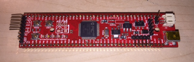
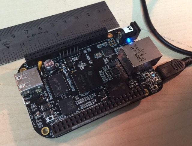
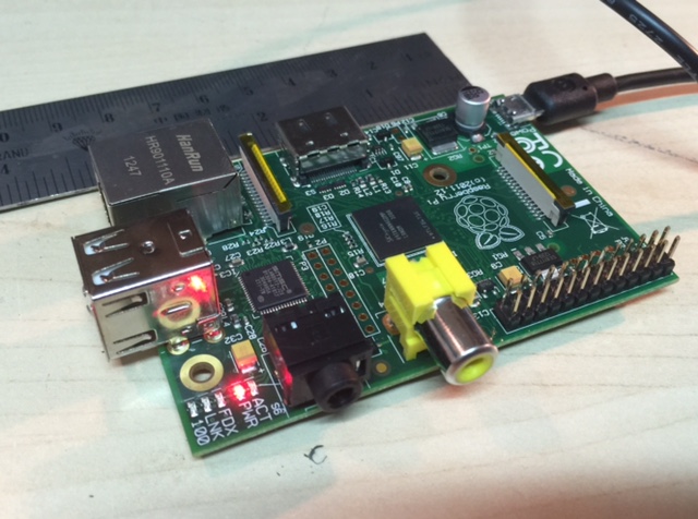
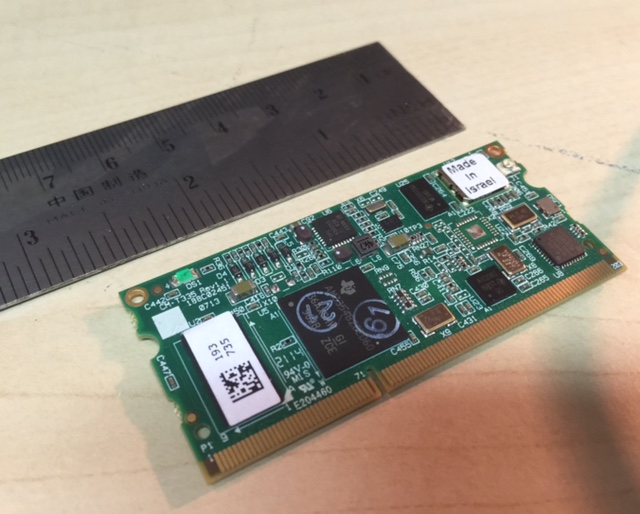

I have used the mbed in the past for prototyping and I agree with Mark that this is a great compromise between functionality, low cost, and ease of development. It also has a real 32 bit C programming model (none of the warts of a pic processor) that make us old C programmers feel right at home. I think it has enough I/O capabilities to keep everyone happy (display/bluetooth/wifi/can/etc) while making the add-on boards affordable. I don't know if the arduino shield model is the right one to pick for add/ons (it may be). Perhaps put some base I/O on the board with options for expansion to keep cost down. I'm ready to replace my rev2 hardware with something that has a touch display as I want a way to see data when driving. I have played around with other options (including can bluetooth adapters) but the elm327 model of accessing data is pretty limited. I give mbed my vote.
Phil H.
Mark,
thanks for all your investigation and evaluation!
Am 30.09.2014 um 16:32 schrieb Mark Webb-Johnson:
Cons: Power consumption, complex low-power modes, lack of CAN although better connectivity that Pi.
So the MBED will use ~3-4 times the power compared to the v2 module. That means it cannot be used for our purpose without low-power / standby modes.
What does "complex" mean? Just difficult to implement on the first hand, or a continuing cause of problems?
Regards, Michael
-- Michael Balzer * Paradestr. 8 * D-42107 Wuppertal Fon 0202 / 272 2201 * Handy 0176 / 206 989 26
Michael,
I think your cut-and-paste is from the wrong option. Here are the specs and pros/cons for the MBED option:
Specification:
Freescale K64F Kinetis K64 MCU (MK64FN1M0VLL12) @120MHz 256KB of RAM 1MB of Flash USB plug-and-play (both disk and serial, although serial needs driver for windows) 1xCAN Embedded design Power consumption: 190mA (@5V) = 1W
Pros: Plenty of RAM+Flash, plug-and-play disk + serial, RTOS, low barrier to entry. Cons: Only single CAN, dual CPU arrangement.
Whatever we choose, power consumption will be an issue.
Here are the power usage figures from my bench, using v1 hardware (remember, this is @12V, not @5V): PIC (normal mode) on, modem powered down (by power toggle switch): 35mA - 42mA PIC (normal mode) on, modem on, gps off: 75mA PIC (normal mode) on, modem on,gps on: 120mA Very short-lived bursts to 160mA at times, presumably while transmitting on GSM
So, the base PIC18 is consuming about 40mA @12V. The MBED option is about 1W. But, the bigger issue is the GSM modem an additional 1.5W. Then, add on bluetooth and wifi, and the problem is exacerbated.
But, we can improve things in a few ways:
We can use low-power modes for the main CPU. For example, the freescale K64F I looked at uses a MK64FN1M0VLL12 CPU, and the data sheet for that shows typical power consumption of 0.135W, but that reduces to 0.005W in low power mode, and almost nothing in stop mode. The 1W power consumption I found also includes powering up all the ancillary peripherals on the demo board - we don’t need that. The 1W power consumption also includes powering the MBED HDK chipset, which is perhaps 1/4 of the power usage. We’ll arrange our circuit so that is only powered up when the board is connected to USB in MBED mode. We’ll use a switching power supply (which is significantly more efficient than the LM we use on the OVMS v2 board. Arthur Hebert gave some figures on this (“OVMS - power drain”, back in June 2014) and he showed the power supply we use is only 40% efficient at 12V (it burns 605 of the power off as heat). An LM2596 switching power supply, by comparison, is 80% efficient at a comparable 5V. Still deciding on final arrangement, but my guess is two separate power supplies - one optimised for 12V car power, and the other for 5V USB power. We’ll use low power modes, sleep modes and power-down for the peripherals, wherever possible.
I have also experimented with another idea that might work. Instead of using the Microchip MCP2515 CAN controller (which costs about US$2/piece and is pretty dumb), use a cheap simple low-power CAN capable microcontroller (about US$3/piece, fully programmable). The main CPU could tell that micro controller what conditions should mean low power wake-up, and then the CAN capable micro controller would signal the main CPU to wake up. This way, we can shut everything down but keep the CAN bus up and have signals on that bus control wake-up of the main CPU. Just an idea, but I did prototype something up to try it, and it seemed to work well.
In general, I think we’ll be ok so long as we treat power consumption as a priority and do everything we can to allow it to be reduced in the fundamental design. My guess is that in our lowest power mode, when car is not charging and not driving and peripherals can be put in low power mode, we’ll be in the 10s of mA (rather than 100s of mA).
Regards, Mark.
On 1 Oct, 2014, at 8:04 pm, Michael Balzer <dexter@expeedo.de> wrote:
Mark,
thanks for all your investigation and evaluation!
Am 30.09.2014 um 16:32 schrieb Mark Webb-Johnson:
Cons: Power consumption, complex low-power modes, lack of CAN although better connectivity that Pi.
So the MBED will use ~3-4 times the power compared to the v2 module. That means it cannot be used for our purpose without low-power / standby modes.
What does "complex" mean? Just difficult to implement on the first hand, or a continuing cause of problems?
Regards, Michael
-- Michael Balzer * Paradestr. 8 * D-42107 Wuppertal Fon 0202 / 272 2201 * Handy 0176 / 206 989 26
<dexter.vcf>_______________________________________________ OvmsDev mailing list OvmsDev@lists.teslaclub.hk http://lists.teslaclub.hk/mailman/listinfo/ovmsdev
On 10/01/2014 06:36 AM, Mark Webb-Johnson wrote:
In general, I think we’ll be ok so long as we treat power consumption as a priority and do everything we can to allow it to be reduced in the fundamental design. My guess is that in our lowest power mode, when car is not charging and not driving and peripherals can be put in low power mode, we’ll be in the 10s of mA (rather than 100s of mA).
I am happy with this perspective, and I would encourage power consumption to remain a high priority.
For what it's worth, I have an OVMS v2 module on an ICE car (my wife's) which sat garaged for 3 weeks between semesters at her college. The OVMS module had completely drained the 12V battery after about two weeks. Obviously I should have thought about that beforehand and disconnected the OVMS module, but I think the module hardware should do better than that.
Thanks,
Lee.
-- *Lee Howard* *Mainpine, Inc. Chief Technology Officer* Tel: +1 866 363 6680 | Fax: +1 360 462 8160 lee.howard@mainpine.com | www.mainpine.com
And the winner is (or at least who I think the winner should be):
MBED (and probably Freescale K64F variant)
Firstly, hats off to Mastro for pointing this out last year. Back then, I didn’t think much of it - it had some good points, but I am very wary of cloud projects, and closed source cloud terrifies me. But, in the past year, the project has come so far, and actually using the hardware left me very impressed.
I think our decision comes down to two choices:
A Linux base, probably compute-module style, with Megabytes of RAM, Gigabytes of Flash, incredible flexibility but a challenge to keep power consumption down. An embedded base, with hundreds of Kilobytes of RAM, Megabytes of Flash, and all the complexities that go along with embedded systems
For me, the MBED architecture now offers a viable compromise between the two. The latest M4 processors give enough flash space (10 times what we have in our OVMS v2 hardware CPU), and RAM (64 times what we have in our OVMS v2 hardware CPU), that the limitation are lifted. More importantly, drag-and-drop programming means that even if flash space became an issue, we could always just offer different firmware for different vehicles - but this time with re-flashing being simply plugging the module into the PC and drag-and-drop the new firmware file in place. Think of it as like having a PICKIT built onto the board, but with the programming software being the file manager of the operating system - the OVMS v3 module shows up as a drive on the desktop and you just drop the new firmware onto it.
Let me explain, in a little more detail, how MBED works.
The MBED boards actually have two processors. The larger processor runs the end-user application (OVMS in our case), and the smaller processor makes up a system called the MBED HDK, based on the CMSIS-DAP standard. The MBED HDK consists of a USB port (standard Micro-B type) connected to the MBED HDK CPU (on the board), some control circuitry, and an ICSP connection to the main CPU. When you plug the MBED into the host O/S, it emulates a flash drive; dropping a file onto that drive programs the file onto the main CPU flash. It also emulates a serial port to the host O/S so when you plug it in you get a serial port to the main CPU. It provides a CMSIS-DAP standard debugger interface (for more advanced debugging). The board itself can be powered from the USB, during MBED development or firmware updating. As well as support for open source GCC toolchain (and others), the MBED included access to an on-line compiler - the code is kept in the cloud, in a shared revision control system, can be compiled there, and binaries downloaded for installation on the boards. There are a large number of open source libraries available for the MBED platform. Coding is in C / C++. The MBED software includes a RTOS with thread support (which should make our job much easier than the current state-based and interrupt systems). There are lots of low-power modes to work with.
The MBED platform provides the lowest barrier-to-entry I’ve ever seen for embedded computing. No serial ports necessary. Just clone the project, tweak, compile, download (with no large IDEs required). Drag-and-drop firmware flashing.
It is also still raw in places. For example, I purchased an NXP LPC4088 MBED board to also experiment with (512KB flash, 96KB RAM, 32MB SDRAM, dual CAN) - only to find that the firmware on the HDK for that board doesn’t support OSX (despite the board being available for a year). That said, the freescale K64F seems pretty close to what we want, and has no such issues.
The other part of the puzzle is how we offer this. Some people want displays, other don’t. For 2G GSM one module was fine, but for 3G we need different modules for Asia, Europe and USA. Some want Bluetooth 2.1, others 4.0 BLE. Some want Wifi, others want cheap. Some want expansion. etc. What I’m thinking of is a baseboard design, with plug-in expansion modules.
The baseboard would contain the MBED HDK + main processor, power supplies, as well as connectors for vehicle, diag, expansion, and USB. It would most likely be based off the K64F open source architecture. We would have several (perhaps 4 or so) plug-in sockets on the baseboard, to allow expansion modules to be plugged in. Each of these sockets would have connections to the main processor as well as expansion ports. The baseboard would give OVMS on 1x CAN port. A 3G module would provide GSM + GPS (and would expose both antenna connectors to the outside world). The expansion board for this would be the same, but we would solder on different modules depending on the frequencies required. A CAN expansion module would use Microchip MCP2515 controllers + MCP2551 transceivers (or something like it) to take SPI bus from the main CPU and expand CAN pins on the vehicle connector. Plug it in, and the system then has one or two more CAN ports available. A wifi expansion module would provide WIFI connectivity. A Bluetooth expansion module would use the HC-?? style bluetooth SPP modules. Similar to the 3G module, we can simply use the same expansion board - just solder on different bluetooth modules for v2.1 or v4.0 BLE. A generic expansion module could be used to add custom functions. For the expansion modules, I’m think of two rows of connectors (one on each side) to provide connectivity and support. Very sturdy and cheap. (something like this: https://www.sparkfun.com/products/10414).
Anyway, those are my thoughts, and suggestions given what is available today. I started this v3 search looking for a Linux base, and really had my heart set on it. But I just can’t solve the power and complexity issues. To meet the goals of having something easy to pick up, MBED really seems the only viable option today.
But, this is no longer my project. There are now so many people involved, and so many end-users. We are about to hit 1,000 users on the openvehicles.com website.
So what do others think?
Regards, Mark.
On 17 Jun, 2014, at 9:06 am, Mark Webb-Johnson <mark@webb-johnson.net> wrote:
Mastro,
Actually, an opportune time as I've made some progress. I'll reply to your mail here, but take into account the follow-up discussions.
The requirements of the OVMS community are diverse. Some want pre-heating, some want relay control, some want a display, some want to reprogram their ECUs, some want GSM, and others want none of these. What we are trying to build is a framework that can be adapted by others.
I am stunned that nothing like this exists on the market. I've spent the past six months looking for a low-power, low-cost, module with wifi+bluetooth and a development environment. Linux/RTOS/whatever. But, I haven't found anything perfect. I understand Kevin's frustration - it seems that GEVCU and OVMS could base on the same hardware, but even with that there appear to be difference in requirement that would just drive up costs for OVMS (or drive down functionality for GEVCU).
On the GEVCU front, I tend to agree with Rickard's comment that the two systems complement each other, but are very different. OVMS could be a telematics module for GEVCU, and would add great functionality to that project.
I spent some time looking at a modular approach. Design a base board with CPU, power and CAN buses. Have that base board support plug-in modules for wifi, bluetooth, cellular, etc. In that way, we can use pre-certified modules, and the user buys what they need. But, the problem with this approach is that if what you need is bluetooth+wifi+cellular, the cost is driven up considerably.
Talking to the China factories, it turns out that bluetooth/wifi is cheap as hell and trivial to implement - so long as we are ARM based. They laugh when we mention Microchip. They are stunned when we say we don't run Linux.
A data plan just for the car is expensive (particular in some countries like USA), but if we can offer hotspot functionality then it can be shared with other devices in the car. For that, we would need to be Linux based.
On the power front, I don't really see the problem as being low power while running, but rather the ability to support a sleep mode when the car is off. We don't need low power always - we just need it for the 90% of the time the car is sitting idle, not charging, not driving. The CPU is not an issue here - they all support a deep sleep mode and we can reduce power requirement to quite literally a trickle. The problem is the comms. We need to be able to be remotely 'woken up' and keeping these GSM/Wifi/Bluetooth modules low power while supporting network stacks is just not possible. The established industry uses USSD messages to remotely wake up their systems, and now I understand why. A GSM module can be designed to be in deep sleep, with very little power usage, but still able to receive a USSD message.
GSM modules like the TELIT and SIMCOM are interesting in that they support running code inside the module itself. This is something we haven't taken advantage of, but offers us the opportunity of offloading a significant amount of what we do.
For me, the requirement comes down to a base framework and module that supports: 32bit CPU with enough grunt, and a low-power sleep mode Dual CAN Async + I2C + SPI + GPIO expansion SD-Card USB Lots of RAM and FLASH Wifi Bluetooth Optional GSM Optional display (or can we get away with bluetooth to a cellphone?)
What is interesting is the advent of low-cost Linux frameworks that are very close to what we need. Things like the BeagleBone and RasberryPi are fascinating, but really designed for HDMI video output - and the overhead of GPU + HDMI is a huge power drain. The closest I've found to what we require is (http://compulab.co.il/products/computer-on-modules/cm-t335/) - pretty amazing little device - low power, wifi+bluetooth, dual CAN, up to 512MB RAM and 1GB FLASH, for around US$50 (in horrendous quantities). I'm working with my contacts in China to see if we can base on a dev board something like that. If they can make Android phones for US$50, we should be able to get the guts of such a device for something similar. Then, add on GSM, take it from a BOM to a product, and we're probably looking at something still <US$150 but with so much more. The closest thing to ideal I've found at the moment is build a baseboard (connectors, power, CAN buses, etc) and have slots to take that CM-T335 module and an optional GSM module. But, I still think we can find something on the China market even closer to what we want/need.
Anyway, those are my thoughts. My conclusion is that to me it seems sensible to work from a low-power linux base with built in dual-can, wifi + bluetooth.
Regards, Mark.

I haven't really been involved with your OVMS project but I have continued to follow it with interest. I really like what you're doing. With the GEVCU project we went through much the same discussion you're having. We obviously settled on using the Arduino Due (eventually rolling our own board based on the Cortex M3 from the Due). The MBed has many similarities to the Arduino Due hardware-wise but uses a totally different development environment and library.
Ultimately I think you are making the right choice. It's very tempting to see something like the BeagleBone Black and want to go that route. But, development of code for something like the BBB is much more complicated unless you write it all in Python. LINUX is awesome on the desktop but I'm not convinced that it is worth the trouble for small embedded projects. Dealing with the complications that linux brings will just make the project more complex and difficult to jump into.
I know of other people using the MBED platform for vehicle use and it seems to be going well for them. I don't see anything really wrong with MBED and I think it will serve your uses very well. In my view going with the MBED platform would serve you well and propel your project into the future.
-Collin Kidder
On Tue, Sep 30, 2014 at 10:34 AM, Mark Webb-Johnson <mark@webb-johnson.net> wrote:
And the winner is (or at least who I think the winner should be):
*MBED (and probably Freescale **K64F variant)*
[image: unknown.jpg]
Firstly, hats off to Mastro for pointing this out last year. Back then, I didn’t think much of it - it had some good points, but I am very wary of cloud projects, and closed source cloud terrifies me. But, in the past year, the project has come so far, and actually using the hardware left me very impressed.
I think our decision comes down to two choices:
- A Linux base, probably compute-module style, with Megabytes of RAM, Gigabytes of Flash, incredible flexibility but a challenge to keep power consumption down.
- An embedded base, with hundreds of Kilobytes of RAM, Megabytes of Flash, and all the complexities that go along with embedded systems
For me, the MBED architecture now offers a viable compromise between the two. The latest M4 processors give enough flash space (10 times what we have in our OVMS v2 hardware CPU), and RAM (64 times what we have in our OVMS v2 hardware CPU), that the limitation are lifted. More importantly, drag-and-drop programming means that even if flash space became an issue, we could always just offer different firmware for different vehicles - but this time with re-flashing being simply plugging the module into the PC and drag-and-drop the new firmware file in place. Think of it as like having a PICKIT built onto the board, but with the programming software being the file manager of the operating system - the OVMS v3 module shows up as a drive on the desktop and you just drop the new firmware onto it.
Let me explain, in a little more detail, how MBED works.
- The MBED boards actually have two processors. The larger processor runs the end-user application (OVMS in our case), and the smaller processor makes up a system called the MBED HDK, based on the CMSIS-DAP standard.
- The MBED HDK consists of a USB port (standard Micro-B type) connected to the MBED HDK CPU (on the board), some control circuitry, and an ICSP connection to the main CPU.
- When you plug the MBED into the host O/S, it emulates a flash drive; dropping a file onto that drive programs the file onto the main CPU flash.
- It also emulates a serial port to the host O/S so when you plug it in you get a serial port to the main CPU.
- It provides a CMSIS-DAP standard debugger interface (for more advanced debugging).
- The board itself can be powered from the USB, during MBED development or firmware updating.
- As well as support for open source GCC toolchain (and others), the MBED included access to an on-line compiler - the code is kept in the cloud, in a shared revision control system, can be compiled there, and binaries downloaded for installation on the boards.
- There are a large number of open source libraries available for the MBED platform.
- Coding is in C / C++.
- The MBED software includes a RTOS with thread support (which should make our job much easier than the current state-based and interrupt systems).
- There are lots of low-power modes to work with.
The MBED platform provides the lowest barrier-to-entry I’ve ever seen for embedded computing. No serial ports necessary. Just clone the project, tweak, compile, download (with no large IDEs required). Drag-and-drop firmware flashing.
It is also still raw in places. For example, I purchased an NXP LPC4088 MBED board to also experiment with (512KB flash, 96KB RAM, 32MB SDRAM, dual CAN) - only to find that the firmware on the HDK for that board doesn’t support OSX (despite the board being available for a year). That said, the freescale K64F seems pretty close to what we want, and has no such issues.
The other part of the puzzle is how we offer this. Some people want displays, other don’t. For 2G GSM one module was fine, but for 3G we need different modules for Asia, Europe and USA. Some want Bluetooth 2.1, others 4.0 BLE. Some want Wifi, others want cheap. Some want expansion. etc. What I’m thinking of is a baseboard design, with plug-in expansion modules.
- The baseboard would contain the MBED HDK + main processor, power supplies, as well as connectors for vehicle, diag, expansion, and USB.
- It would most likely be based off the K64F open source architecture.
- We would have several (perhaps 4 or so) plug-in sockets on the baseboard, to allow expansion modules to be plugged in. Each of these sockets would have connections to the main processor as well as expansion ports.
- The baseboard would give OVMS on 1x CAN port.
- A 3G module would provide GSM + GPS (and would expose both antenna connectors to the outside world). The expansion board for this would be the same, but we would solder on different modules depending on the frequencies required.
- A CAN expansion module would use Microchip MCP2515 controllers + MCP2551 transceivers (or something like it) to take SPI bus from the main CPU and expand CAN pins on the vehicle connector. Plug it in, and the system then has one or two more CAN ports available.
- A wifi expansion module would provide WIFI connectivity.
- A Bluetooth expansion module would use the HC-?? style bluetooth SPP modules. Similar to the 3G module, we can simply use the same expansion board - just solder on different bluetooth modules for v2.1 or v4.0 BLE.
- A generic expansion module could be used to add custom functions.
- For the expansion modules, I’m think of two rows of connectors (one on each side) to provide connectivity and support. Very sturdy and cheap. (something like this: https://www.sparkfun.com/products/10414).
Anyway, those are my thoughts, and suggestions given what is available today. I started this v3 search looking for a Linux base, and really had my heart set on it. But I just can’t solve the power and complexity issues. To meet the goals of having something easy to pick up, MBED really seems the only viable option today.
But, this is no longer my project. There are now so many people involved, and so many end-users. We are about to hit 1,000 users on the openvehicles.com website.
So what do others think?
Regards, Mark.
On 17 Jun, 2014, at 9:06 am, Mark Webb-Johnson <mark@webb-johnson.net> wrote:
Mastro,
Actually, an opportune time as I've made some progress. I'll reply to your mail here, but take into account the follow-up discussions.
The requirements of the OVMS community are diverse. Some want pre-heating, some want relay control, some want a display, some want to reprogram their ECUs, some want GSM, and others want none of these. What we are trying to build is a framework that can be adapted by others.
I am stunned that nothing like this exists on the market. I've spent the past six months looking for a low-power, low-cost, module with wifi+bluetooth and a development environment. Linux/RTOS/whatever. But, I haven't found anything perfect. I understand Kevin's frustration - it seems that GEVCU and OVMS could base on the same hardware, but even with that there appear to be difference in requirement that would just drive up costs for OVMS (or drive down functionality for GEVCU).
On the GEVCU front, I tend to agree with Rickard's comment that the two systems complement each other, but are very different. OVMS could be a telematics module for GEVCU, and would add great functionality to that project.
I spent some time looking at a modular approach. Design a base board with CPU, power and CAN buses. Have that base board support plug-in modules for wifi, bluetooth, cellular, etc. In that way, we can use pre-certified modules, and the user buys what they need. But, the problem with this approach is that if what you need is bluetooth+wifi+cellular, the cost is driven up considerably.
Talking to the China factories, it turns out that bluetooth/wifi is cheap as hell and trivial to implement - so long as we are ARM based. They laugh when we mention Microchip. They are stunned when we say we don't run Linux.
A data plan just for the car is expensive (particular in some countries like USA), but if we can offer hotspot functionality then it can be shared with other devices in the car. For that, we would need to be Linux based.
On the power front, I don't really see the problem as being low power while running, but rather the ability to support a sleep mode when the car is off. We don't need low power always - we just need it for the 90% of the time the car is sitting idle, not charging, not driving. The CPU is not an issue here - they all support a deep sleep mode and we can reduce power requirement to quite literally a trickle. The problem is the comms. We need to be able to be remotely 'woken up' and keeping these GSM/Wifi/Bluetooth modules low power while supporting network stacks is just not possible. The established industry uses USSD messages to remotely wake up their systems, and now I understand why. A GSM module can be designed to be in deep sleep, with very little power usage, but still able to receive a USSD message.
GSM modules like the TELIT and SIMCOM are interesting in that they support running code inside the module itself. This is something we haven't taken advantage of, but offers us the opportunity of offloading a significant amount of what we do.
For me, the requirement comes down to a base framework and module that supports:
32bit CPU with enough grunt, and a low-power sleep mode
Dual CAN
Async + I2C + SPI + GPIO expansion
SD-Card
USB
Lots of RAM and FLASH
Wifi
Bluetooth
Optional GSM
Optional display (or can we get away with bluetooth to a cellphone?)
What is interesting is the advent of low-cost Linux frameworks that are very close to what we need. Things like the BeagleBone and RasberryPi are fascinating, but really designed for HDMI video output - and the overhead of GPU + HDMI is a huge power drain. The closest I've found to what we require is ( http://compulab.co.il/products/computer-on-modules/cm-t335/) - pretty amazing little device - low power, wifi+bluetooth, dual CAN, up to 512MB RAM and 1GB FLASH, for around US$50 (in horrendous quantities). I'm working with my contacts in China to see if we can base on a dev board something like that. If they can make Android phones for US$50, we should be able to get the guts of such a device for something similar. Then, add on GSM, take it from a BOM to a product, and we're probably looking at something still <US$150 but with so much more. The closest thing to ideal I've found at the moment is build a baseboard (connectors, power, CAN buses, etc) and have slots to take that CM-T335 module and an optional GSM module. But, I still think we can find something on the China market even closer to what we want/need.
Anyway, those are my thoughts. My conclusion is that to me it seems sensible to work from a low-power linux base with built in dual-can, wifi + bluetooth.
Regards, Mark.
OvmsDev mailing list OvmsDev@lists.teslaclub.hk http://lists.teslaclub.hk/mailman/listinfo/ovmsdev
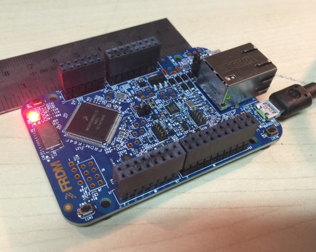
It¹s been interesting to watch the GEVCU development and the inevitable move to a more robust hardware platform which will be based on the Cinch Enclosure and connector (version 6). Something many people wanted at the start of the project.
IMO we need a robust hardware platform and the more we can focus software developers on a single platform the better for us all my vote is hardware that¹s compatible with GEVCU and the amazing libraries that exist today (including Colin¹s excellent CAN library).
Kevin Sharpe | Founder & Chair of Trustees Tel: +44 122 566 7544 ext: 800 | Skype: zerocarbonworld kevin.sharpe@zerocarbonworld.org <mailto:kevin.sharpe@zerocarbonworld.org> | www.zerocarbonworld.org <http://www.zerocarbonworld.org/> | twitter.com/zerocarbonworld <http://twitter.com/ZCWcharlie>
Zero Carbon World is a UK Registered Charity #1141347 From: Collin Kidder <collink@kkmfg.com> Reply-To: OVMS Developers <ovmsdev@lists.teslaclub.hk> Date: Tuesday, 30 September 2014 15:53 To: OVMS Developers <ovmsdev@lists.teslaclub.hk> Subject: Re: [Ovmsdev] OVMS v3
I haven't really been involved with your OVMS project but I have continued to follow it with interest. I really like what you're doing. With the GEVCU project we went through much the same discussion you're having. We obviously settled on using the Arduino Due (eventually rolling our own board based on the Cortex M3 from the Due). The MBed has many similarities to the Arduino Due hardware-wise but uses a totally different development environment and library.
Ultimately I think you are making the right choice. It's very tempting to see something like the BeagleBone Black and want to go that route. But, development of code for something like the BBB is much more complicated unless you write it all in Python. LINUX is awesome on the desktop but I'm not convinced that it is worth the trouble for small embedded projects. Dealing with the complications that linux brings will just make the project more complex and difficult to jump into.
I know of other people using the MBED platform for vehicle use and it seems to be going well for them. I don't see anything really wrong with MBED and I think it will serve your uses very well. In my view going with the MBED platform would serve you well and propel your project into the future.
-Collin Kidder
On Tue, Sep 30, 2014 at 10:34 AM, Mark Webb-Johnson <mark@webb-johnson.net> wrote:
And the winner is (or at least who I think the winner should be):
MBED (and probably Freescale K64F variant)
Firstly, hats off to Mastro for pointing this out last year. Back then, I didn¹t think much of it - it had some good points, but I am very wary of cloud projects, and closed source cloud terrifies me. But, in the past year, the project has come so far, and actually using the hardware left me very impressed.
I think our decision comes down to two choices:
- A Linux base, probably compute-module style, with Megabytes of RAM, Gigabytes of Flash, incredible flexibility but a challenge to keep power consumption down.
- An embedded base, with hundreds of Kilobytes of RAM, Megabytes of Flash, and all the complexities that go along with embedded systems
For me, the MBED architecture now offers a viable compromise between the two. The latest M4 processors give enough flash space (10 times what we have in our OVMS v2 hardware CPU), and RAM (64 times what we have in our OVMS v2 hardware CPU), that the limitation are lifted. More importantly, drag-and-drop programming means that even if flash space became an issue, we could always just offer different firmware for different vehicles - but this time with re-flashing being simply plugging the module into the PC and drag-and-drop the new firmware file in place. Think of it as like having a PICKIT built onto the board, but with the programming software being the file manager of the operating system - the OVMS v3 module shows up as a drive on the desktop and you just drop the new firmware onto it.
Let me explain, in a little more detail, how MBED works.
- The MBED boards actually have two processors. The larger processor runs the end-user application (OVMS in our case), and the smaller processor makes up a system called the MBED HDK, based on the CMSIS-DAP standard.
- The MBED HDK consists of a USB port (standard Micro-B type) connected to the MBED HDK CPU (on the board), some control circuitry, and an ICSP connection to the main CPU.
- When you plug the MBED into the host O/S, it emulates a flash drive; dropping a file onto that drive programs the file onto the main CPU flash.
- It also emulates a serial port to the host O/S so when you plug it in you get a serial port to the main CPU.
- It provides a CMSIS-DAP standard debugger interface (for more advanced debugging).
- The board itself can be powered from the USB, during MBED development or firmware updating.
- As well as support for open source GCC toolchain (and others), the MBED included access to an on-line compiler - the code is kept in the cloud, in a shared revision control system, can be compiled there, and binaries downloaded for installation on the boards.
- There are a large number of open source libraries available for the MBED platform.
- Coding is in C / C++.
- The MBED software includes a RTOS with thread support (which should make our job much easier than the current state-based and interrupt systems).
- There are lots of low-power modes to work with.
The MBED platform provides the lowest barrier-to-entry I¹ve ever seen for embedded computing. No serial ports necessary. Just clone the project, tweak, compile, download (with no large IDEs required). Drag-and-drop firmware flashing.
It is also still raw in places. For example, I purchased an NXP LPC4088 MBED board to also experiment with (512KB flash, 96KB RAM, 32MB SDRAM, dual CAN) - only to find that the firmware on the HDK for that board doesn¹t support OSX (despite the board being available for a year). That said, the freescale K64F seems pretty close to what we want, and has no such issues.
The other part of the puzzle is how we offer this. Some people want displays, other don¹t. For 2G GSM one module was fine, but for 3G we need different modules for Asia, Europe and USA. Some want Bluetooth 2.1, others 4.0 BLE. Some want Wifi, others want cheap. Some want expansion. etc. What I¹m thinking of is a baseboard design, with plug-in expansion modules.
- The baseboard would contain the MBED HDK + main processor, power supplies, as well as connectors for vehicle, diag, expansion, and USB.
- It would most likely be based off the K64F open source architecture.
- We would have several (perhaps 4 or so) plug-in sockets on the baseboard, to allow expansion modules to be plugged in. Each of these sockets would have connections to the main processor as well as expansion ports.
- The baseboard would give OVMS on 1x CAN port.
- A 3G module would provide GSM + GPS (and would expose both antenna connectors to the outside world). The expansion board for this would be the same, but we would solder on different modules depending on the frequencies required.
- A CAN expansion module would use Microchip MCP2515 controllers + MCP2551 transceivers (or something like it) to take SPI bus from the main CPU and expand CAN pins on the vehicle connector. Plug it in, and the system then has one or two more CAN ports available.
- A wifi expansion module would provide WIFI connectivity.
- A Bluetooth expansion module would use the HC-?? style bluetooth SPP modules. Similar to the 3G module, we can simply use the same expansion board
- just solder on different bluetooth modules for v2.1 or v4.0 BLE.
- A generic expansion module could be used to add custom functions.
- For the expansion modules, I¹m think of two rows of connectors (one on each side) to provide connectivity and support. Very sturdy and cheap. (something like this: https://www.sparkfun.com/products/10414).
Anyway, those are my thoughts, and suggestions given what is available today. I started this v3 search looking for a Linux base, and really had my heart set on it. But I just can¹t solve the power and complexity issues. To meet the goals of having something easy to pick up, MBED really seems the only viable option today.
But, this is no longer my project. There are now so many people involved, and so many end-users. We are about to hit 1,000 users on the openvehicles.com <http://openvehicles.com> website.
So what do others think?
Regards, Mark.
On 17 Jun, 2014, at 9:06 am, Mark Webb-Johnson <mark@webb-johnson.net> wrote:
Mastro,
Actually, an opportune time as I've made some progress. I'll reply to your mail here, but take into account the follow-up discussions.
- The requirements of the OVMS community are diverse. Some want pre-heating, some want relay control, some want a display, some want to reprogram their ECUs, some want GSM, and others want none of these. What we are trying to build is a framework that can be adapted by others.
- I am stunned that nothing like this exists on the market. I've spent the past six months looking for a low-power, low-cost, module with wifi+bluetooth and a development environment. Linux/RTOS/whatever. But, I haven't found anything perfect. I understand Kevin's frustration - it seems that GEVCU and OVMS could base on the same hardware, but even with that there appear to be difference in requirement that would just drive up costs for OVMS (or drive down functionality for GEVCU).
- On the GEVCU front, I tend to agree with Rickard's comment that the two systems complement each other, but are very different. OVMS could be a telematics module for GEVCU, and would add great functionality to that project.
- I spent some time looking at a modular approach. Design a base board with CPU, power and CAN buses. Have that base board support plug-in modules for wifi, bluetooth, cellular, etc. In that way, we can use pre-certified modules, and the user buys what they need. But, the problem with this approach is that if what you need is bluetooth+wifi+cellular, the cost is driven up considerably.
- Talking to the China factories, it turns out that bluetooth/wifi is cheap as hell and trivial to implement - so long as we are ARM based. They laugh when we mention Microchip. They are stunned when we say we don't run Linux.
- A data plan just for the car is expensive (particular in some countries like USA), but if we can offer hotspot functionality then it can be shared with other devices in the car. For that, we would need to be Linux based.
- On the power front, I don't really see the problem as being low power while running, but rather the ability to support a sleep mode when the car is off. We don't need low power always - we just need it for the 90% of the time the car is sitting idle, not charging, not driving. The CPU is not an issue here
- they all support a deep sleep mode and we can reduce power requirement to quite literally a trickle. The problem is the comms. We need to be able to be remotely 'woken up' and keeping these GSM/Wifi/Bluetooth modules low power while supporting network stacks is just not possible. The established industry uses USSD messages to remotely wake up their systems, and now I understand why. A GSM module can be designed to be in deep sleep, with very little power usage, but still able to receive a USSD message.
- GSM modules like the TELIT and SIMCOM are interesting in that they support running code inside the module itself. This is something we haven't taken advantage of, but offers us the opportunity of offloading a significant amount of what we do.
- For me, the requirement comes down to a base framework and module that supports:
- 32bit CPU with enough grunt, and a low-power sleep mode
- Dual CAN
- Async + I2C + SPI + GPIO expansion
- SD-Card
- USB
- Lots of RAM and FLASH
- Wifi
- Bluetooth
- Optional GSM
- Optional display (or can we get away with bluetooth to a cellphone?)
- What is interesting is the advent of low-cost Linux frameworks that are very close to what we need. Things like the BeagleBone and RasberryPi are fascinating, but really designed for HDMI video output - and the overhead of GPU + HDMI is a huge power drain. The closest I've found to what we require is (http://compulab.co.il/products/computer-on-modules/cm-t335/) - pretty amazing little device - low power, wifi+bluetooth, dual CAN, up to 512MB RAM and 1GB FLASH, for around US$50 (in horrendous quantities). I'm working with my contacts in China to see if we can base on a dev board something like that. If they can make Android phones for US$50, we should be able to get the guts of such a device for something similar. Then, add on GSM, take it from a BOM to a product, and we're probably looking at something still <US$150 but with so much more. The closest thing to ideal I've found at the moment is build a baseboard (connectors, power, CAN buses, etc) and have slots to take that CM-T335 module and an optional GSM module. But, I still think we can find something on the China market even closer to what we want/need.
Anyway, those are my thoughts. My conclusion is that to me it seems sensible to work from a low-power linux base with built in dual-can, wifi + bluetooth.
Regards, Mark.
OvmsDev mailing list OvmsDev@lists.teslaclub.hk http://lists.teslaclub.hk/mailman/listinfo/ovmsdev
_______________________________________________ OvmsDev mailing list OvmsDev@lists.teslaclub.hkhttp://lists.teslaclub.hk/mailman/listinfo/ovmsdev
Kevin, Colin,
Last we discussed this, didn't we come to the conclusion that there wasn't enough overlap between the two projects? Different goals, and most importantly, requirements. I am also concerned about the US$600 cost of the gevcu (without stuff like bluetooth, GSM and GPS which we need) - I don't think people are going to pay that much for a telematics module.
Or, have things changed?
Regards, Mark
On 1 Oct, 2014, at 7:07 pm, Kevin Sharpe <kevin.sharpe@zerocarbonworld.org> wrote:
It’s been interesting to watch the GEVCU development and the inevitable move to a more robust hardware platform which will be based on the Cinch Enclosure and connector (version 6). Something many people wanted at the start of the project.
IMO we need a robust hardware platform and the more we can focus software developers on a single platform the better for us all… my vote is hardware that’s compatible with GEVCU and the amazing libraries that exist today (including Colin’s excellent CAN library).
Kevin Sharpe | Founder & Chair of TrusteesTel: +44 122 566 7544 ext: 800 | Skype: zerocarbonworld kevin.sharpe@zerocarbonworld.org | www.zerocarbonworld.org | twitter.com/zerocarbonworld
Zero Carbon World is a UK Registered Charity #1141347 From: Collin Kidder <collink@kkmfg.com> Reply-To: OVMS Developers <ovmsdev@lists.teslaclub.hk> Date: Tuesday, 30 September 2014 15:53 To: OVMS Developers <ovmsdev@lists.teslaclub.hk> Subject: Re: [Ovmsdev] OVMS v3
I haven't really been involved with your OVMS project but I have continued to follow it with interest. I really like what you're doing. With the GEVCU project we went through much the same discussion you're having. We obviously settled on using the Arduino Due (eventually rolling our own board based on the Cortex M3 from the Due). The MBed has many similarities to the Arduino Due hardware-wise but uses a totally different development environment and library.
Ultimately I think you are making the right choice. It's very tempting to see something like the BeagleBone Black and want to go that route. But, development of code for something like the BBB is much more complicated unless you write it all in Python. LINUX is awesome on the desktop but I'm not convinced that it is worth the trouble for small embedded projects. Dealing with the complications that linux brings will just make the project more complex and difficult to jump into.
I know of other people using the MBED platform for vehicle use and it seems to be going well for them. I don't see anything really wrong with MBED and I think it will serve your uses very well. In my view going with the MBED platform would serve you well and propel your project into the future.
-Collin Kidder
On Tue, Sep 30, 2014 at 10:34 AM, Mark Webb-Johnson <mark@webb-johnson.net> wrote:
And the winner is (or at least who I think the winner should be):
MBED (and probably Freescale K64F variant)
<unknown.jpg>
Firstly, hats off to Mastro for pointing this out last year. Back then, I didn’t think much of it - it had some good points, but I am very wary of cloud projects, and closed source cloud terrifies me. But, in the past year, the project has come so far, and actually using the hardware left me very impressed.
I think our decision comes down to two choices:
A Linux base, probably compute-module style, with Megabytes of RAM, Gigabytes of Flash, incredible flexibility but a challenge to keep power consumption down. An embedded base, with hundreds of Kilobytes of RAM, Megabytes of Flash, and all the complexities that go along with embedded systems
For me, the MBED architecture now offers a viable compromise between the two. The latest M4 processors give enough flash space (10 times what we have in our OVMS v2 hardware CPU), and RAM (64 times what we have in our OVMS v2 hardware CPU), that the limitation are lifted. More importantly, drag-and-drop programming means that even if flash space became an issue, we could always just offer different firmware for different vehicles - but this time with re-flashing being simply plugging the module into the PC and drag-and-drop the new firmware file in place. Think of it as like having a PICKIT built onto the board, but with the programming software being the file manager of the operating system - the OVMS v3 module shows up as a drive on the desktop and you just drop the new firmware onto it.
Let me explain, in a little more detail, how MBED works.
The MBED boards actually have two processors. The larger processor runs the end-user application (OVMS in our case), and the smaller processor makes up a system called the MBED HDK, based on the CMSIS-DAP standard. The MBED HDK consists of a USB port (standard Micro-B type) connected to the MBED HDK CPU (on the board), some control circuitry, and an ICSP connection to the main CPU. When you plug the MBED into the host O/S, it emulates a flash drive; dropping a file onto that drive programs the file onto the main CPU flash. It also emulates a serial port to the host O/S so when you plug it in you get a serial port to the main CPU. It provides a CMSIS-DAP standard debugger interface (for more advanced debugging). The board itself can be powered from the USB, during MBED development or firmware updating. As well as support for open source GCC toolchain (and others), the MBED included access to an on-line compiler - the code is kept in the cloud, in a shared revision control system, can be compiled there, and binaries downloaded for installation on the boards. There are a large number of open source libraries available for the MBED platform. Coding is in C / C++. The MBED software includes a RTOS with thread support (which should make our job much easier than the current state-based and interrupt systems). There are lots of low-power modes to work with.
The MBED platform provides the lowest barrier-to-entry I’ve ever seen for embedded computing. No serial ports necessary. Just clone the project, tweak, compile, download (with no large IDEs required). Drag-and-drop firmware flashing.
It is also still raw in places. For example, I purchased an NXP LPC4088 MBED board to also experiment with (512KB flash, 96KB RAM, 32MB SDRAM, dual CAN) - only to find that the firmware on the HDK for that board doesn’t support OSX (despite the board being available for a year). That said, the freescale K64F seems pretty close to what we want, and has no such issues.
The other part of the puzzle is how we offer this. Some people want displays, other don’t. For 2G GSM one module was fine, but for 3G we need different modules for Asia, Europe and USA. Some want Bluetooth 2.1, others 4.0 BLE. Some want Wifi, others want cheap. Some want expansion. etc. What I’m thinking of is a baseboard design, with plug-in expansion modules.
The baseboard would contain the MBED HDK + main processor, power supplies, as well as connectors for vehicle, diag, expansion, and USB. It would most likely be based off the K64F open source architecture. We would have several (perhaps 4 or so) plug-in sockets on the baseboard, to allow expansion modules to be plugged in. Each of these sockets would have connections to the main processor as well as expansion ports. The baseboard would give OVMS on 1x CAN port. A 3G module would provide GSM + GPS (and would expose both antenna connectors to the outside world). The expansion board for this would be the same, but we would solder on different modules depending on the frequencies required. A CAN expansion module would use Microchip MCP2515 controllers + MCP2551 transceivers (or something like it) to take SPI bus from the main CPU and expand CAN pins on the vehicle connector. Plug it in, and the system then has one or two more CAN ports available. A wifi expansion module would provide WIFI connectivity. A Bluetooth expansion module would use the HC-?? style bluetooth SPP modules. Similar to the 3G module, we can simply use the same expansion board - just solder on different bluetooth modules for v2.1 or v4.0 BLE. A generic expansion module could be used to add custom functions. For the expansion modules, I’m think of two rows of connectors (one on each side) to provide connectivity and support. Very sturdy and cheap. (something like this: https://www.sparkfun.com/products/10414).
Anyway, those are my thoughts, and suggestions given what is available today. I started this v3 search looking for a Linux base, and really had my heart set on it. But I just can’t solve the power and complexity issues. To meet the goals of having something easy to pick up, MBED really seems the only viable option today.
But, this is no longer my project. There are now so many people involved, and so many end-users. We are about to hit 1,000 users on the openvehicles.com website.
So what do others think?
Regards, Mark.
On 17 Jun, 2014, at 9:06 am, Mark Webb-Johnson <mark@webb-johnson.net> wrote:
Mastro,
Actually, an opportune time as I've made some progress. I'll reply to your mail here, but take into account the follow-up discussions.
The requirements of the OVMS community are diverse. Some want pre-heating, some want relay control, some want a display, some want to reprogram their ECUs, some want GSM, and others want none of these. What we are trying to build is a framework that can be adapted by others.
I am stunned that nothing like this exists on the market. I've spent the past six months looking for a low-power, low-cost, module with wifi+bluetooth and a development environment. Linux/RTOS/whatever. But, I haven't found anything perfect. I understand Kevin's frustration - it seems that GEVCU and OVMS could base on the same hardware, but even with that there appear to be difference in requirement that would just drive up costs for OVMS (or drive down functionality for GEVCU).
On the GEVCU front, I tend to agree with Rickard's comment that the two systems complement each other, but are very different. OVMS could be a telematics module for GEVCU, and would add great functionality to that project.
I spent some time looking at a modular approach. Design a base board with CPU, power and CAN buses. Have that base board support plug-in modules for wifi, bluetooth, cellular, etc. In that way, we can use pre-certified modules, and the user buys what they need. But, the problem with this approach is that if what you need is bluetooth+wifi+cellular, the cost is driven up considerably.
Talking to the China factories, it turns out that bluetooth/wifi is cheap as hell and trivial to implement - so long as we are ARM based. They laugh when we mention Microchip. They are stunned when we say we don't run Linux.
A data plan just for the car is expensive (particular in some countries like USA), but if we can offer hotspot functionality then it can be shared with other devices in the car. For that, we would need to be Linux based.
On the power front, I don't really see the problem as being low power while running, but rather the ability to support a sleep mode when the car is off. We don't need low power always - we just need it for the 90% of the time the car is sitting idle, not charging, not driving. The CPU is not an issue here - they all support a deep sleep mode and we can reduce power requirement to quite literally a trickle. The problem is the comms. We need to be able to be remotely 'woken up' and keeping these GSM/Wifi/Bluetooth modules low power while supporting network stacks is just not possible. The established industry uses USSD messages to remotely wake up their systems, and now I understand why. A GSM module can be designed to be in deep sleep, with very little power usage, but still able to receive a USSD message.
GSM modules like the TELIT and SIMCOM are interesting in that they support running code inside the module itself. This is something we haven't taken advantage of, but offers us the opportunity of offloading a significant amount of what we do.
For me, the requirement comes down to a base framework and module that supports: 32bit CPU with enough grunt, and a low-power sleep mode Dual CAN Async + I2C + SPI + GPIO expansion SD-Card USB Lots of RAM and FLASH Wifi Bluetooth Optional GSM Optional display (or can we get away with bluetooth to a cellphone?)
What is interesting is the advent of low-cost Linux frameworks that are very close to what we need. Things like the BeagleBone and RasberryPi are fascinating, but really designed for HDMI video output - and the overhead of GPU + HDMI is a huge power drain. The closest I've found to what we require is (http://compulab.co.il/products/computer-on-modules/cm-t335/) - pretty amazing little device - low power, wifi+bluetooth, dual CAN, up to 512MB RAM and 1GB FLASH, for around US$50 (in horrendous quantities). I'm working with my contacts in China to see if we can base on a dev board something like that. If they can make Android phones for US$50, we should be able to get the guts of such a device for something similar. Then, add on GSM, take it from a BOM to a product, and we're probably looking at something still <US$150 but with so much more. The closest thing to ideal I've found at the moment is build a baseboard (connectors, power, CAN buses, etc) and have slots to take that CM-T335 module and an optional GSM module. But, I still think we can find something on the China market even closer to what we want/need.
Anyway, those are my thoughts. My conclusion is that to me it seems sensible to work from a low-power linux base with built in dual-can, wifi + bluetooth.
Regards, Mark.
OvmsDev mailing list OvmsDev@lists.teslaclub.hk http://lists.teslaclub.hk/mailman/listinfo/ovmsdev
_______________________________________________ OvmsDev mailing list OvmsDev@lists.teslaclub.hkhttp://lists.teslaclub.hk/mailman/listinfo/ovmsdev <unknown.jpg>
OvmsDev mailing list OvmsDev@lists.teslaclub.hk http://lists.teslaclub.hk/mailman/listinfo/ovmsdev

Hi,
i vote for MBED. Linux with C/C++ is fine. i think the price for the GEVCU is to high for this project. Must under $200 for all stuff.
Bye Michael J.
Am 01.10.2014 um 13:40 schrieb Mark Webb-Johnson <mark@webb-johnson.net>:
Kevin, Colin,
Last we discussed this, didn't we come to the conclusion that there wasn't enough overlap between the two projects? Different goals, and most importantly, requirements. I am also concerned about the US$600 cost of the gevcu (without stuff like bluetooth, GSM and GPS which we need) - I don't think people are going to pay that much for a telematics module.
Or, have things changed?
Regards, Mark
On 1 Oct, 2014, at 7:07 pm, Kevin Sharpe <kevin.sharpe@zerocarbonworld.org <mailto:kevin.sharpe@zerocarbonworld.org>> wrote:
It’s been interesting to watch the GEVCU development and the inevitable move to a more robust hardware platform which will be based on the Cinch Enclosure and connector (version 6). Something many people wanted at the start of the project.
IMO we need a robust hardware platform and the more we can focus software developers on a single platform the better for us all… my vote is hardware that’s compatible with GEVCU and the amazing libraries that exist today (including Colin’s excellent CAN library).
Kevin Sharpe | Founder & Chair of TrusteesTel: +44 122 566 7544 ext: 800 | Skype: zerocarbonworld kevin.sharpe@zerocarbonworld.org <mailto:kevin.sharpe@zerocarbonworld.org>| www.zerocarbonworld.org <http://www.zerocarbonworld.org/> | twitter.com/zerocarbonworld <http://twitter.com/ZCWcharlie>
Zero Carbon World is a UK Registered Charity #1141347 From: Collin Kidder <collink@kkmfg.com <mailto:collink@kkmfg.com>> Reply-To: OVMS Developers <ovmsdev@lists.teslaclub.hk <mailto:ovmsdev@lists.teslaclub.hk>> Date: Tuesday, 30 September 2014 15:53 To: OVMS Developers <ovmsdev@lists.teslaclub.hk <mailto:ovmsdev@lists.teslaclub.hk>> Subject: Re: [Ovmsdev] OVMS v3
I haven't really been involved with your OVMS project but I have continued to follow it with interest. I really like what you're doing. With the GEVCU project we went through much the same discussion you're having. We obviously settled on using the Arduino Due (eventually rolling our own board based on the Cortex M3 from the Due). The MBed has many similarities to the Arduino Due hardware-wise but uses a totally different development environment and library.
Ultimately I think you are making the right choice. It's very tempting to see something like the BeagleBone Black and want to go that route. But, development of code for something like the BBB is much more complicated unless you write it all in Python. LINUX is awesome on the desktop but I'm not convinced that it is worth the trouble for small embedded projects. Dealing with the complications that linux brings will just make the project more complex and difficult to jump into.
I know of other people using the MBED platform for vehicle use and it seems to be going well for them. I don't see anything really wrong with MBED and I think it will serve your uses very well. In my view going with the MBED platform would serve you well and propel your project into the future.
-Collin Kidder
On Tue, Sep 30, 2014 at 10:34 AM, Mark Webb-Johnson <mark@webb-johnson.net <mailto:mark@webb-johnson.net>> wrote:
And the winner is (or at least who I think the winner should be):
MBED (and probably Freescale K64F variant)
<unknown.jpg>
Firstly, hats off to Mastro for pointing this out last year. Back then, I didn’t think much of it - it had some good points, but I am very wary of cloud projects, and closed source cloud terrifies me. But, in the past year, the project has come so far, and actually using the hardware left me very impressed.
I think our decision comes down to two choices:
A Linux base, probably compute-module style, with Megabytes of RAM, Gigabytes of Flash, incredible flexibility but a challenge to keep power consumption down. An embedded base, with hundreds of Kilobytes of RAM, Megabytes of Flash, and all the complexities that go along with embedded systems
For me, the MBED architecture now offers a viable compromise between the two. The latest M4 processors give enough flash space (10 times what we have in our OVMS v2 hardware CPU), and RAM (64 times what we have in our OVMS v2 hardware CPU), that the limitation are lifted. More importantly, drag-and-drop programming means that even if flash space became an issue, we could always just offer different firmware for different vehicles - but this time with re-flashing being simply plugging the module into the PC and drag-and-drop the new firmware file in place. Think of it as like having a PICKIT built onto the board, but with the programming software being the file manager of the operating system - the OVMS v3 module shows up as a drive on the desktop and you just drop the new firmware onto it.
Let me explain, in a little more detail, how MBED works.
The MBED boards actually have two processors. The larger processor runs the end-user application (OVMS in our case), and the smaller processor makes up a system called the MBED HDK, based on the CMSIS-DAP standard. The MBED HDK consists of a USB port (standard Micro-B type) connected to the MBED HDK CPU (on the board), some control circuitry, and an ICSP connection to the main CPU. When you plug the MBED into the host O/S, it emulates a flash drive; dropping a file onto that drive programs the file onto the main CPU flash. It also emulates a serial port to the host O/S so when you plug it in you get a serial port to the main CPU. It provides a CMSIS-DAP standard debugger interface (for more advanced debugging). The board itself can be powered from the USB, during MBED development or firmware updating. As well as support for open source GCC toolchain (and others), the MBED included access to an on-line compiler - the code is kept in the cloud, in a shared revision control system, can be compiled there, and binaries downloaded for installation on the boards. There are a large number of open source libraries available for the MBED platform. Coding is in C / C++. The MBED software includes a RTOS with thread support (which should make our job much easier than the current state-based and interrupt systems). There are lots of low-power modes to work with.
The MBED platform provides the lowest barrier-to-entry I’ve ever seen for embedded computing. No serial ports necessary. Just clone the project, tweak, compile, download (with no large IDEs required). Drag-and-drop firmware flashing.
It is also still raw in places. For example, I purchased an NXP LPC4088 MBED board to also experiment with (512KB flash, 96KB RAM, 32MB SDRAM, dual CAN) - only to find that the firmware on the HDK for that board doesn’t support OSX (despite the board being available for a year). That said, the freescale K64F seems pretty close to what we want, and has no such issues.
The other part of the puzzle is how we offer this. Some people want displays, other don’t. For 2G GSM one module was fine, but for 3G we need different modules for Asia, Europe and USA. Some want Bluetooth 2.1, others 4.0 BLE. Some want Wifi, others want cheap. Some want expansion. etc. What I’m thinking of is a baseboard design, with plug-in expansion modules.
The baseboard would contain the MBED HDK + main processor, power supplies, as well as connectors for vehicle, diag, expansion, and USB. It would most likely be based off the K64F open source architecture. We would have several (perhaps 4 or so) plug-in sockets on the baseboard, to allow expansion modules to be plugged in. Each of these sockets would have connections to the main processor as well as expansion ports. The baseboard would give OVMS on 1x CAN port. A 3G module would provide GSM + GPS (and would expose both antenna connectors to the outside world). The expansion board for this would be the same, but we would solder on different modules depending on the frequencies required. A CAN expansion module would use Microchip MCP2515 controllers + MCP2551 transceivers (or something like it) to take SPI bus from the main CPU and expand CAN pins on the vehicle connector. Plug it in, and the system then has one or two more CAN ports available. A wifi expansion module would provide WIFI connectivity. A Bluetooth expansion module would use the HC-?? style bluetooth SPP modules. Similar to the 3G module, we can simply use the same expansion board - just solder on different bluetooth modules for v2.1 or v4.0 BLE. A generic expansion module could be used to add custom functions. For the expansion modules, I’m think of two rows of connectors (one on each side) to provide connectivity and support. Very sturdy and cheap. (something like this: https://www.sparkfun.com/products/10414 <https://www.sparkfun.com/products/10414>).
Anyway, those are my thoughts, and suggestions given what is available today. I started this v3 search looking for a Linux base, and really had my heart set on it. But I just can’t solve the power and complexity issues. To meet the goals of having something easy to pick up, MBED really seems the only viable option today.
But, this is no longer my project. There are now so many people involved, and so many end-users. We are about to hit 1,000 users on the openvehicles.com <http://openvehicles.com/> website.
So what do others think?
Regards, Mark.
On 17 Jun, 2014, at 9:06 am, Mark Webb-Johnson <mark@webb-johnson.net <mailto:mark@webb-johnson.net>> wrote:
Mastro,
Actually, an opportune time as I've made some progress. I'll reply to your mail here, but take into account the follow-up discussions.
The requirements of the OVMS community are diverse. Some want pre-heating, some want relay control, some want a display, some want to reprogram their ECUs, some want GSM, and others want none of these. What we are trying to build is a framework that can be adapted by others.
I am stunned that nothing like this exists on the market. I've spent the past six months looking for a low-power, low-cost, module with wifi+bluetooth and a development environment. Linux/RTOS/whatever. But, I haven't found anything perfect. I understand Kevin's frustration - it seems that GEVCU and OVMS could base on the same hardware, but even with that there appear to be difference in requirement that would just drive up costs for OVMS (or drive down functionality for GEVCU).
On the GEVCU front, I tend to agree with Rickard's comment that the two systems complement each other, but are very different. OVMS could be a telematics module for GEVCU, and would add great functionality to that project.
I spent some time looking at a modular approach. Design a base board with CPU, power and CAN buses. Have that base board support plug-in modules for wifi, bluetooth, cellular, etc. In that way, we can use pre-certified modules, and the user buys what they need. But, the problem with this approach is that if what you need is bluetooth+wifi+cellular, the cost is driven up considerably.
Talking to the China factories, it turns out that bluetooth/wifi is cheap as hell and trivial to implement - so long as we are ARM based. They laugh when we mention Microchip. They are stunned when we say we don't run Linux.
A data plan just for the car is expensive (particular in some countries like USA), but if we can offer hotspot functionality then it can be shared with other devices in the car. For that, we would need to be Linux based.
On the power front, I don't really see the problem as being low power while running, but rather the ability to support a sleep mode when the car is off. We don't need low power always - we just need it for the 90% of the time the car is sitting idle, not charging, not driving. The CPU is not an issue here - they all support a deep sleep mode and we can reduce power requirement to quite literally a trickle. The problem is the comms. We need to be able to be remotely 'woken up' and keeping these GSM/Wifi/Bluetooth modules low power while supporting network stacks is just not possible. The established industry uses USSD messages to remotely wake up their systems, and now I understand why. A GSM module can be designed to be in deep sleep, with very little power usage, but still able to receive a USSD message.
GSM modules like the TELIT and SIMCOM are interesting in that they support running code inside the module itself. This is something we haven't taken advantage of, but offers us the opportunity of offloading a significant amount of what we do.
For me, the requirement comes down to a base framework and module that supports: 32bit CPU with enough grunt, and a low-power sleep mode Dual CAN Async + I2C + SPI + GPIO expansion SD-Card USB Lots of RAM and FLASH Wifi Bluetooth Optional GSM Optional display (or can we get away with bluetooth to a cellphone?)
What is interesting is the advent of low-cost Linux frameworks that are very close to what we need. Things like the BeagleBone and RasberryPi are fascinating, but really designed for HDMI video output - and the overhead of GPU + HDMI is a huge power drain. The closest I've found to what we require is (http://compulab.co.il/products/computer-on-modules/cm-t335/ <http://compulab.co.il/products/computer-on-modules/cm-t335/>) - pretty amazing little device - low power, wifi+bluetooth, dual CAN, up to 512MB RAM and 1GB FLASH, for around US$50 (in horrendous quantities). I'm working with my contacts in China to see if we can base on a dev board something like that. If they can make Android phones for US$50, we should be able to get the guts of such a device for something similar. Then, add on GSM, take it from a BOM to a product, and we're probably looking at something still <US$150 but with so much more. The closest thing to ideal I've found at the moment is build a baseboard (connectors, power, CAN buses, etc) and have slots to take that CM-T335 module and an optional GSM module. But, I still think we can find something on the China market even closer to what we want/need.
Anyway, those are my thoughts. My conclusion is that to me it seems sensible to work from a low-power linux base with built in dual-can, wifi + bluetooth.
Regards, Mark.
OvmsDev mailing list OvmsDev@lists.teslaclub.hk <mailto:OvmsDev@lists.teslaclub.hk> http://lists.teslaclub.hk/mailman/listinfo/ovmsdev <http://lists.teslaclub.hk/mailman/listinfo/ovmsdev>
_______________________________________________ OvmsDev mailing list OvmsDev@lists.teslaclub.hk <mailto:OvmsDev@lists.teslaclub.hk>http://lists.teslaclub.hk/mailman/listinfo/ovmsdev <http://lists.teslaclub.hk/mailman/listinfo/ovmsdev><unknown.jpg>
OvmsDev mailing list OvmsDev@lists.teslaclub.hk <mailto:OvmsDev@lists.teslaclub.hk> http://lists.teslaclub.hk/mailman/listinfo/ovmsdev <http://lists.teslaclub.hk/mailman/listinfo/ovmsdev>
OvmsDev mailing list OvmsDev@lists.teslaclub.hk <mailto:OvmsDev@lists.teslaclub.hk> http://lists.teslaclub.hk/mailman/listinfo/ovmsdev <http://lists.teslaclub.hk/mailman/listinfo/ovmsdev>
Yes, of course I wish that you all could go with the GEVCU hardware. It was discussed in the past and the GEVCU project is somewhat inching more toward what would have worked for OVMS as well. But, the price is certainly way over what seems to be tenable for your project. Many of our hardware choices were not the cheapest options but people are willing to spend $600 on an ECU for their car. For telemetrics the cost aspect is much more important.
Which is why I said that I think MBED would work fine for you. It is very much like the Arduino Due (using a Cortex M4 instead of the Due's M3) and seems like a good fit for your project. It's powerful while still being reasonably energy efficient, cheap, and easy to program.
On Wed, Oct 1, 2014 at 8:00 AM, Michael Jochum <mikeljo@me.com> wrote:
Hi,
i vote for MBED. Linux with C/C++ is fine. i think the price for the GEVCU is to high for this project. Must under $200 for all stuff.
Bye Michael J.
Am 01.10.2014 um 13:40 schrieb Mark Webb-Johnson <mark@webb-johnson.net>:
Kevin, Colin,
Last we discussed this, didn't we come to the conclusion that there wasn't enough overlap between the two projects? Different goals, and most importantly, requirements. I am also concerned about the US$600 cost of the gevcu (without stuff like bluetooth, GSM and GPS which we need) - I don't think people are going to pay that much for a telematics module.
Or, have things changed?
Regards, Mark
On 1 Oct, 2014, at 7:07 pm, Kevin Sharpe <kevin.sharpe@zerocarbonworld.org> wrote:
It’s been interesting to watch the GEVCU development and the inevitable move to a more robust hardware platform which will be based on the Cinch Enclosure and connector (version 6). Something many people wanted at the start of the project.
IMO we need a robust hardware platform and the more we can focus software developers on a single platform the better for us all… my vote is hardware that’s compatible with GEVCU and the amazing libraries that exist today (including Colin’s excellent CAN library).
Kevin Sharpe | Founder & Chair of Trustees Tel: +44 122 566 7544 ext: 800 | Skype: zerocarbonworld kevin.sharpe@zerocarbonworld.org <kevin.sharpe@zerocarbonworld.org>| www.zerocarbonworld.org | twitter.com/zerocarbonworld <http://twitter.com/ZCWcharlie> Zero Carbon World is a UK Registered Charity #1141347 From: Collin Kidder <collink@kkmfg.com> Reply-To: OVMS Developers <ovmsdev@lists.teslaclub.hk> Date: Tuesday, 30 September 2014 15:53 To: OVMS Developers <ovmsdev@lists.teslaclub.hk> Subject: Re: [Ovmsdev] OVMS v3
I haven't really been involved with your OVMS project but I have continued to follow it with interest. I really like what you're doing. With the GEVCU project we went through much the same discussion you're having. We obviously settled on using the Arduino Due (eventually rolling our own board based on the Cortex M3 from the Due). The MBed has many similarities to the Arduino Due hardware-wise but uses a totally different development environment and library.
Ultimately I think you are making the right choice. It's very tempting to see something like the BeagleBone Black and want to go that route. But, development of code for something like the BBB is much more complicated unless you write it all in Python. LINUX is awesome on the desktop but I'm not convinced that it is worth the trouble for small embedded projects. Dealing with the complications that linux brings will just make the project more complex and difficult to jump into.
I know of other people using the MBED platform for vehicle use and it seems to be going well for them. I don't see anything really wrong with MBED and I think it will serve your uses very well. In my view going with the MBED platform would serve you well and propel your project into the future.
-Collin Kidder
On Tue, Sep 30, 2014 at 10:34 AM, Mark Webb-Johnson <mark@webb-johnson.net
wrote:
And the winner is (or at least who I think the winner should be):
*MBED (and probably Freescale **K64F variant)*
<unknown.jpg>
Firstly, hats off to Mastro for pointing this out last year. Back then, I didn’t think much of it - it had some good points, but I am very wary of cloud projects, and closed source cloud terrifies me. But, in the past year, the project has come so far, and actually using the hardware left me very impressed.
I think our decision comes down to two choices:
- A Linux base, probably compute-module style, with Megabytes of RAM, Gigabytes of Flash, incredible flexibility but a challenge to keep power consumption down.
- An embedded base, with hundreds of Kilobytes of RAM, Megabytes of Flash, and all the complexities that go along with embedded systems
For me, the MBED architecture now offers a viable compromise between the two. The latest M4 processors give enough flash space (10 times what we have in our OVMS v2 hardware CPU), and RAM (64 times what we have in our OVMS v2 hardware CPU), that the limitation are lifted. More importantly, drag-and-drop programming means that even if flash space became an issue, we could always just offer different firmware for different vehicles - but this time with re-flashing being simply plugging the module into the PC and drag-and-drop the new firmware file in place. Think of it as like having a PICKIT built onto the board, but with the programming software being the file manager of the operating system - the OVMS v3 module shows up as a drive on the desktop and you just drop the new firmware onto it.
Let me explain, in a little more detail, how MBED works.
- The MBED boards actually have two processors. The larger processor runs the end-user application (OVMS in our case), and the smaller processor makes up a system called the MBED HDK, based on the CMSIS-DAP standard.
- The MBED HDK consists of a USB port (standard Micro-B type) connected to the MBED HDK CPU (on the board), some control circuitry, and an ICSP connection to the main CPU.
- When you plug the MBED into the host O/S, it emulates a flash drive; dropping a file onto that drive programs the file onto the main CPU flash.
- It also emulates a serial port to the host O/S so when you plug it in you get a serial port to the main CPU.
- It provides a CMSIS-DAP standard debugger interface (for more advanced debugging).
- The board itself can be powered from the USB, during MBED development or firmware updating.
- As well as support for open source GCC toolchain (and others), the MBED included access to an on-line compiler - the code is kept in the cloud, in a shared revision control system, can be compiled there, and binaries downloaded for installation on the boards.
- There are a large number of open source libraries available for the MBED platform.
- Coding is in C / C++.
- The MBED software includes a RTOS with thread support (which should make our job much easier than the current state-based and interrupt systems).
- There are lots of low-power modes to work with.
The MBED platform provides the lowest barrier-to-entry I’ve ever seen for embedded computing. No serial ports necessary. Just clone the project, tweak, compile, download (with no large IDEs required). Drag-and-drop firmware flashing.
It is also still raw in places. For example, I purchased an NXP LPC4088 MBED board to also experiment with (512KB flash, 96KB RAM, 32MB SDRAM, dual CAN) - only to find that the firmware on the HDK for that board doesn’t support OSX (despite the board being available for a year). That said, the freescale K64F seems pretty close to what we want, and has no such issues.
The other part of the puzzle is how we offer this. Some people want displays, other don’t. For 2G GSM one module was fine, but for 3G we need different modules for Asia, Europe and USA. Some want Bluetooth 2.1, others 4.0 BLE. Some want Wifi, others want cheap. Some want expansion. etc. What I’m thinking of is a baseboard design, with plug-in expansion modules.
- The baseboard would contain the MBED HDK + main processor, power supplies, as well as connectors for vehicle, diag, expansion, and USB.
- It would most likely be based off the K64F open source architecture.
- We would have several (perhaps 4 or so) plug-in sockets on the baseboard, to allow expansion modules to be plugged in. Each of these sockets would have connections to the main processor as well as expansion ports.
- The baseboard would give OVMS on 1x CAN port.
- A 3G module would provide GSM + GPS (and would expose both antenna connectors to the outside world). The expansion board for this would be the same, but we would solder on different modules depending on the frequencies required.
- A CAN expansion module would use Microchip MCP2515 controllers + MCP2551 transceivers (or something like it) to take SPI bus from the main CPU and expand CAN pins on the vehicle connector. Plug it in, and the system then has one or two more CAN ports available.
- A wifi expansion module would provide WIFI connectivity.
- A Bluetooth expansion module would use the HC-?? style bluetooth SPP modules. Similar to the 3G module, we can simply use the same expansion board - just solder on different bluetooth modules for v2.1 or v4.0 BLE.
- A generic expansion module could be used to add custom functions.
- For the expansion modules, I’m think of two rows of connectors (one on each side) to provide connectivity and support. Very sturdy and cheap. (something like this: https://www.sparkfun.com/products/10414).
Anyway, those are my thoughts, and suggestions given what is available today. I started this v3 search looking for a Linux base, and really had my heart set on it. But I just can’t solve the power and complexity issues. To meet the goals of having something easy to pick up, MBED really seems the only viable option today.
But, this is no longer my project. There are now so many people involved, and so many end-users. We are about to hit 1,000 users on the openvehicles.com website.
So what do others think?
Regards, Mark.
On 17 Jun, 2014, at 9:06 am, Mark Webb-Johnson <mark@webb-johnson.net> wrote:
Mastro,
Actually, an opportune time as I've made some progress. I'll reply to your mail here, but take into account the follow-up discussions.
The requirements of the OVMS community are diverse. Some want pre-heating, some want relay control, some want a display, some want to reprogram their ECUs, some want GSM, and others want none of these. What we are trying to build is a framework that can be adapted by others.
I am stunned that nothing like this exists on the market. I've spent the past six months looking for a low-power, low-cost, module with wifi+bluetooth and a development environment. Linux/RTOS/whatever. But, I haven't found anything perfect. I understand Kevin's frustration - it seems that GEVCU and OVMS could base on the same hardware, but even with that there appear to be difference in requirement that would just drive up costs for OVMS (or drive down functionality for GEVCU).
On the GEVCU front, I tend to agree with Rickard's comment that the two systems complement each other, but are very different. OVMS could be a telematics module for GEVCU, and would add great functionality to that project.
I spent some time looking at a modular approach. Design a base board with CPU, power and CAN buses. Have that base board support plug-in modules for wifi, bluetooth, cellular, etc. In that way, we can use pre-certified modules, and the user buys what they need. But, the problem with this approach is that if what you need is bluetooth+wifi+cellular, the cost is driven up considerably.
Talking to the China factories, it turns out that bluetooth/wifi is cheap as hell and trivial to implement - so long as we are ARM based. They laugh when we mention Microchip. They are stunned when we say we don't run Linux.
A data plan just for the car is expensive (particular in some countries like USA), but if we can offer hotspot functionality then it can be shared with other devices in the car. For that, we would need to be Linux based.
On the power front, I don't really see the problem as being low power while running, but rather the ability to support a sleep mode when the car is off. We don't need low power always - we just need it for the 90% of the time the car is sitting idle, not charging, not driving. The CPU is not an issue here - they all support a deep sleep mode and we can reduce power requirement to quite literally a trickle. The problem is the comms. We need to be able to be remotely 'woken up' and keeping these GSM/Wifi/Bluetooth modules low power while supporting network stacks is just not possible. The established industry uses USSD messages to remotely wake up their systems, and now I understand why. A GSM module can be designed to be in deep sleep, with very little power usage, but still able to receive a USSD message.
GSM modules like the TELIT and SIMCOM are interesting in that they support running code inside the module itself. This is something we haven't taken advantage of, but offers us the opportunity of offloading a significant amount of what we do.
For me, the requirement comes down to a base framework and module that supports:
32bit CPU with enough grunt, and a low-power sleep mode
Dual CAN
Async + I2C + SPI + GPIO expansion
SD-Card
USB
Lots of RAM and FLASH
Wifi
Bluetooth
Optional GSM
Optional display (or can we get away with bluetooth to a cellphone?)
What is interesting is the advent of low-cost Linux frameworks that are very close to what we need. Things like the BeagleBone and RasberryPi are fascinating, but really designed for HDMI video output - and the overhead of GPU + HDMI is a huge power drain. The closest I've found to what we require is ( http://compulab.co.il/products/computer-on-modules/cm-t335/) - pretty amazing little device - low power, wifi+bluetooth, dual CAN, up to 512MB RAM and 1GB FLASH, for around US$50 (in horrendous quantities). I'm working with my contacts in China to see if we can base on a dev board something like that. If they can make Android phones for US$50, we should be able to get the guts of such a device for something similar. Then, add on GSM, take it from a BOM to a product, and we're probably looking at something still <US$150 but with so much more. The closest thing to ideal I've found at the moment is build a baseboard (connectors, power, CAN buses, etc) and have slots to take that CM-T335 module and an optional GSM module. But, I still think we can find something on the China market even closer to what we want/need.
Anyway, those are my thoughts. My conclusion is that to me it seems sensible to work from a low-power linux base with built in dual-can, wifi + bluetooth.
Regards, Mark.
OvmsDev mailing list OvmsDev@lists.teslaclub.hk http://lists.teslaclub.hk/mailman/listinfo/ovmsdev
_______________________________________________ OvmsDev mailing list OvmsDev@lists.teslaclub.hk http://lists.teslaclub.hk/mailman/listinfo/ovmsdev
<unknown.jpg>
OvmsDev mailing list OvmsDev@lists.teslaclub.hk http://lists.teslaclub.hk/mailman/listinfo/ovmsdev
OvmsDev mailing list OvmsDev@lists.teslaclub.hk http://lists.teslaclub.hk/mailman/listinfo/ovmsdev
OvmsDev mailing list OvmsDev@lists.teslaclub.hk http://lists.teslaclub.hk/mailman/listinfo/ovmsdev

I forgot to mention in my other post, the LPC1768 *does* have two CAN buses. The MBED version of it is $50 but it includes things like an Ethernet transceiver which won't be necessary for a production board. The chip itself is ~$11 on mouser.
On Wed, Oct 1, 2014 at 11:17 AM, Collin Kidder <collink@kkmfg.com> wrote:
Yes, of course I wish that you all could go with the GEVCU hardware. It was discussed in the past and the GEVCU project is somewhat inching more toward what would have worked for OVMS as well. But, the price is certainly way over what seems to be tenable for your project. Many of our hardware choices were not the cheapest options but people are willing to spend $600 on an ECU for their car. For telemetrics the cost aspect is much more important.
Which is why I said that I think MBED would work fine for you. It is very much like the Arduino Due (using a Cortex M4 instead of the Due's M3) and seems like a good fit for your project. It's powerful while still being reasonably energy efficient, cheap, and easy to program.
On Wed, Oct 1, 2014 at 8:00 AM, Michael Jochum <mikeljo@me.com> wrote:
Hi,
i vote for MBED. Linux with C/C++ is fine. i think the price for the GEVCU is to high for this project. Must under $200 for all stuff.
Bye Michael J.
Am 01.10.2014 um 13:40 schrieb Mark Webb-Johnson <mark@webb-johnson.net>:
Kevin, Colin,
Last we discussed this, didn't we come to the conclusion that there wasn't enough overlap between the two projects? Different goals, and most importantly, requirements. I am also concerned about the US$600 cost of the gevcu (without stuff like bluetooth, GSM and GPS which we need) - I don't think people are going to pay that much for a telematics module.
Or, have things changed?
Regards, Mark
On 1 Oct, 2014, at 7:07 pm, Kevin Sharpe < kevin.sharpe@zerocarbonworld.org> wrote:
It’s been interesting to watch the GEVCU development and the inevitable move to a more robust hardware platform which will be based on the Cinch Enclosure and connector (version 6). Something many people wanted at the start of the project.
IMO we need a robust hardware platform and the more we can focus software developers on a single platform the better for us all… my vote is hardware that’s compatible with GEVCU and the amazing libraries that exist today (including Colin’s excellent CAN library).
Kevin Sharpe | Founder & Chair of Trustees Tel: +44 122 566 7544 ext: 800 | Skype: zerocarbonworld kevin.sharpe@zerocarbonworld.org <kevin.sharpe@zerocarbonworld.org>| www.zerocarbonworld.org | twitter.com/zerocarbonworld <http://twitter.com/ZCWcharlie> Zero Carbon World is a UK Registered Charity #1141347 From: Collin Kidder <collink@kkmfg.com> Reply-To: OVMS Developers <ovmsdev@lists.teslaclub.hk> Date: Tuesday, 30 September 2014 15:53 To: OVMS Developers <ovmsdev@lists.teslaclub.hk> Subject: Re: [Ovmsdev] OVMS v3
I haven't really been involved with your OVMS project but I have continued to follow it with interest. I really like what you're doing. With the GEVCU project we went through much the same discussion you're having. We obviously settled on using the Arduino Due (eventually rolling our own board based on the Cortex M3 from the Due). The MBed has many similarities to the Arduino Due hardware-wise but uses a totally different development environment and library.
Ultimately I think you are making the right choice. It's very tempting to see something like the BeagleBone Black and want to go that route. But, development of code for something like the BBB is much more complicated unless you write it all in Python. LINUX is awesome on the desktop but I'm not convinced that it is worth the trouble for small embedded projects. Dealing with the complications that linux brings will just make the project more complex and difficult to jump into.
I know of other people using the MBED platform for vehicle use and it seems to be going well for them. I don't see anything really wrong with MBED and I think it will serve your uses very well. In my view going with the MBED platform would serve you well and propel your project into the future.
-Collin Kidder
On Tue, Sep 30, 2014 at 10:34 AM, Mark Webb-Johnson < mark@webb-johnson.net> wrote:
And the winner is (or at least who I think the winner should be):
*MBED (and probably Freescale **K64F variant)*
<unknown.jpg>
Firstly, hats off to Mastro for pointing this out last year. Back then, I didn’t think much of it - it had some good points, but I am very wary of cloud projects, and closed source cloud terrifies me. But, in the past year, the project has come so far, and actually using the hardware left me very impressed.
I think our decision comes down to two choices:
- A Linux base, probably compute-module style, with Megabytes of RAM, Gigabytes of Flash, incredible flexibility but a challenge to keep power consumption down.
- An embedded base, with hundreds of Kilobytes of RAM, Megabytes of Flash, and all the complexities that go along with embedded systems
For me, the MBED architecture now offers a viable compromise between the two. The latest M4 processors give enough flash space (10 times what we have in our OVMS v2 hardware CPU), and RAM (64 times what we have in our OVMS v2 hardware CPU), that the limitation are lifted. More importantly, drag-and-drop programming means that even if flash space became an issue, we could always just offer different firmware for different vehicles - but this time with re-flashing being simply plugging the module into the PC and drag-and-drop the new firmware file in place. Think of it as like having a PICKIT built onto the board, but with the programming software being the file manager of the operating system - the OVMS v3 module shows up as a drive on the desktop and you just drop the new firmware onto it.
Let me explain, in a little more detail, how MBED works.
- The MBED boards actually have two processors. The larger processor runs the end-user application (OVMS in our case), and the smaller processor makes up a system called the MBED HDK, based on the CMSIS-DAP standard.
- The MBED HDK consists of a USB port (standard Micro-B type) connected to the MBED HDK CPU (on the board), some control circuitry, and an ICSP connection to the main CPU.
- When you plug the MBED into the host O/S, it emulates a flash drive; dropping a file onto that drive programs the file onto the main CPU flash.
- It also emulates a serial port to the host O/S so when you plug it in you get a serial port to the main CPU.
- It provides a CMSIS-DAP standard debugger interface (for more advanced debugging).
- The board itself can be powered from the USB, during MBED development or firmware updating.
- As well as support for open source GCC toolchain (and others), the MBED included access to an on-line compiler - the code is kept in the cloud, in a shared revision control system, can be compiled there, and binaries downloaded for installation on the boards.
- There are a large number of open source libraries available for the MBED platform.
- Coding is in C / C++.
- The MBED software includes a RTOS with thread support (which should make our job much easier than the current state-based and interrupt systems).
- There are lots of low-power modes to work with.
The MBED platform provides the lowest barrier-to-entry I’ve ever seen for embedded computing. No serial ports necessary. Just clone the project, tweak, compile, download (with no large IDEs required). Drag-and-drop firmware flashing.
It is also still raw in places. For example, I purchased an NXP LPC4088 MBED board to also experiment with (512KB flash, 96KB RAM, 32MB SDRAM, dual CAN) - only to find that the firmware on the HDK for that board doesn’t support OSX (despite the board being available for a year). That said, the freescale K64F seems pretty close to what we want, and has no such issues.
The other part of the puzzle is how we offer this. Some people want displays, other don’t. For 2G GSM one module was fine, but for 3G we need different modules for Asia, Europe and USA. Some want Bluetooth 2.1, others 4.0 BLE. Some want Wifi, others want cheap. Some want expansion. etc. What I’m thinking of is a baseboard design, with plug-in expansion modules.
- The baseboard would contain the MBED HDK + main processor, power supplies, as well as connectors for vehicle, diag, expansion, and USB.
- It would most likely be based off the K64F open source architecture.
- We would have several (perhaps 4 or so) plug-in sockets on the baseboard, to allow expansion modules to be plugged in. Each of these sockets would have connections to the main processor as well as expansion ports.
- The baseboard would give OVMS on 1x CAN port.
- A 3G module would provide GSM + GPS (and would expose both antenna connectors to the outside world). The expansion board for this would be the same, but we would solder on different modules depending on the frequencies required.
- A CAN expansion module would use Microchip MCP2515 controllers
- MCP2551 transceivers (or something like it) to take SPI bus from the main CPU and expand CAN pins on the vehicle connector. Plug it in, and the system then has one or two more CAN ports available.
- A wifi expansion module would provide WIFI connectivity.
- A Bluetooth expansion module would use the HC-?? style bluetooth SPP modules. Similar to the 3G module, we can simply use the same expansion board - just solder on different bluetooth modules for v2.1 or v4.0 BLE.
- A generic expansion module could be used to add custom functions.
- For the expansion modules, I’m think of two rows of connectors (one on each side) to provide connectivity and support. Very sturdy and cheap. (something like this: https://www.sparkfun.com/products/10414 ).
Anyway, those are my thoughts, and suggestions given what is available today. I started this v3 search looking for a Linux base, and really had my heart set on it. But I just can’t solve the power and complexity issues. To meet the goals of having something easy to pick up, MBED really seems the only viable option today.
But, this is no longer my project. There are now so many people involved, and so many end-users. We are about to hit 1,000 users on the openvehicles.com website.
So what do others think?
Regards, Mark.
On 17 Jun, 2014, at 9:06 am, Mark Webb-Johnson <mark@webb-johnson.net> wrote:
Mastro,
Actually, an opportune time as I've made some progress. I'll reply to your mail here, but take into account the follow-up discussions.
The requirements of the OVMS community are diverse. Some want pre-heating, some want relay control, some want a display, some want to reprogram their ECUs, some want GSM, and others want none of these. What we are trying to build is a framework that can be adapted by others.
I am stunned that nothing like this exists on the market. I've spent the past six months looking for a low-power, low-cost, module with wifi+bluetooth and a development environment. Linux/RTOS/whatever. But, I haven't found anything perfect. I understand Kevin's frustration - it seems that GEVCU and OVMS could base on the same hardware, but even with that there appear to be difference in requirement that would just drive up costs for OVMS (or drive down functionality for GEVCU).
On the GEVCU front, I tend to agree with Rickard's comment that the two systems complement each other, but are very different. OVMS could be a telematics module for GEVCU, and would add great functionality to that project.
I spent some time looking at a modular approach. Design a base board with CPU, power and CAN buses. Have that base board support plug-in modules for wifi, bluetooth, cellular, etc. In that way, we can use pre-certified modules, and the user buys what they need. But, the problem with this approach is that if what you need is bluetooth+wifi+cellular, the cost is driven up considerably.
Talking to the China factories, it turns out that bluetooth/wifi is cheap as hell and trivial to implement - so long as we are ARM based. They laugh when we mention Microchip. They are stunned when we say we don't run Linux.
A data plan just for the car is expensive (particular in some countries like USA), but if we can offer hotspot functionality then it can be shared with other devices in the car. For that, we would need to be Linux based.
On the power front, I don't really see the problem as being low power while running, but rather the ability to support a sleep mode when the car is off. We don't need low power always - we just need it for the 90% of the time the car is sitting idle, not charging, not driving. The CPU is not an issue here - they all support a deep sleep mode and we can reduce power requirement to quite literally a trickle. The problem is the comms. We need to be able to be remotely 'woken up' and keeping these GSM/Wifi/Bluetooth modules low power while supporting network stacks is just not possible. The established industry uses USSD messages to remotely wake up their systems, and now I understand why. A GSM module can be designed to be in deep sleep, with very little power usage, but still able to receive a USSD message.
GSM modules like the TELIT and SIMCOM are interesting in that they support running code inside the module itself. This is something we haven't taken advantage of, but offers us the opportunity of offloading a significant amount of what we do.
For me, the requirement comes down to a base framework and module that supports:
32bit CPU with enough grunt, and a low-power sleep mode
Dual CAN
Async + I2C + SPI + GPIO expansion
SD-Card
USB
Lots of RAM and FLASH
Wifi
Bluetooth
Optional GSM
Optional display (or can we get away with bluetooth to a cellphone?)
What is interesting is the advent of low-cost Linux frameworks that are very close to what we need. Things like the BeagleBone and RasberryPi are fascinating, but really designed for HDMI video output - and the overhead of GPU + HDMI is a huge power drain. The closest I've found to what we require is ( http://compulab.co.il/products/computer-on-modules/cm-t335/) - pretty amazing little device - low power, wifi+bluetooth, dual CAN, up to 512MB RAM and 1GB FLASH, for around US$50 (in horrendous quantities). I'm working with my contacts in China to see if we can base on a dev board something like that. If they can make Android phones for US$50, we should be able to get the guts of such a device for something similar. Then, add on GSM, take it from a BOM to a product, and we're probably looking at something still <US$150 but with so much more. The closest thing to ideal I've found at the moment is build a baseboard (connectors, power, CAN buses, etc) and have slots to take that CM-T335 module and an optional GSM module. But, I still think we can find something on the China market even closer to what we want/need.
Anyway, those are my thoughts. My conclusion is that to me it seems sensible to work from a low-power linux base with built in dual-can, wifi + bluetooth.
Regards, Mark.
OvmsDev mailing list OvmsDev@lists.teslaclub.hk http://lists.teslaclub.hk/mailman/listinfo/ovmsdev
_______________________________________________ OvmsDev mailing list OvmsDev@lists.teslaclub.hk http://lists.teslaclub.hk/mailman/listinfo/ovmsdev
<unknown.jpg>
OvmsDev mailing list OvmsDev@lists.teslaclub.hk http://lists.teslaclub.hk/mailman/listinfo/ovmsdev
OvmsDev mailing list OvmsDev@lists.teslaclub.hk http://lists.teslaclub.hk/mailman/listinfo/ovmsdev
OvmsDev mailing list OvmsDev@lists.teslaclub.hk http://lists.teslaclub.hk/mailman/listinfo/ovmsdev
OvmsDev mailing list OvmsDev@lists.teslaclub.hk http://lists.teslaclub.hk/mailman/listinfo/ovmsdev
Here I am! I'm happy that I helped choosing the platform, I really like the mbed. I like even more the freescale version, as they are one of the biggest names in automotive microcontrollers (even if our model is not an automotive-specific one). There are devices in the same product line that have 2 CAN buses. I had a quick chat with a Freescale engineer, John McLellan, and asked him about the Mbed porting; he confirmed that the binaries should be cross-compatible between similar products, and it shouldn't be hard to add support for the second CAN bus. So we can start developing for the Mbed board and then use another chip in production with little effort. His office is just across the road from Mbed offices in Austin, TX, and he told me to write him an email and he will investigate the matter further. We even hypotized using the OVMS as a basic development platform. So, if anyone have more questions for him, just ask and then we can prepare an email with everything. About the Mbed HDK, I'm not really sure if it's the right thing to include it in the final product; it adds cost and occupies precious space. I would find a way to use a simple bootloader. Another note: as Jeremy points out, and as I proposed from the start, the NXP board have 2 CAN buses and a very cheap (34$) development board available http://www.nxp.com/demoboard/OM13000.html and has an integrated *real* debugger that can be detached by sawing the board to save space. Regards Mastro Gippo
2014-10-01 21:17 GMT+02:00 Jeremy Whaling <jeremy.whaling@gmail.com>:
I forgot to mention in my other post, the LPC1768 *does* have two CAN buses. The MBED version of it is $50 but it includes things like an Ethernet transceiver which won't be necessary for a production board. The chip itself is ~$11 on mouser.
On Wed, Oct 1, 2014 at 11:17 AM, Collin Kidder <collink@kkmfg.com> wrote:
Yes, of course I wish that you all could go with the GEVCU hardware. It was discussed in the past and the GEVCU project is somewhat inching more toward what would have worked for OVMS as well. But, the price is certainly way over what seems to be tenable for your project. Many of our hardware choices were not the cheapest options but people are willing to spend $600 on an ECU for their car. For telemetrics the cost aspect is much more important.
Which is why I said that I think MBED would work fine for you. It is very much like the Arduino Due (using a Cortex M4 instead of the Due's M3) and seems like a good fit for your project. It's powerful while still being reasonably energy efficient, cheap, and easy to program.
On Wed, Oct 1, 2014 at 8:00 AM, Michael Jochum <mikeljo@me.com> wrote:
Hi,
i vote for MBED. Linux with C/C++ is fine. i think the price for the GEVCU is to high for this project. Must under $200 for all stuff.
Bye Michael J.
Am 01.10.2014 um 13:40 schrieb Mark Webb-Johnson <mark@webb-johnson.net
:
Kevin, Colin,
Last we discussed this, didn't we come to the conclusion that there wasn't enough overlap between the two projects? Different goals, and most importantly, requirements. I am also concerned about the US$600 cost of the gevcu (without stuff like bluetooth, GSM and GPS which we need) - I don't think people are going to pay that much for a telematics module.
Or, have things changed?
Regards, Mark
On 1 Oct, 2014, at 7:07 pm, Kevin Sharpe < kevin.sharpe@zerocarbonworld.org> wrote:
It’s been interesting to watch the GEVCU development and the inevitable move to a more robust hardware platform which will be based on the Cinch Enclosure and connector (version 6). Something many people wanted at the start of the project.
IMO we need a robust hardware platform and the more we can focus software developers on a single platform the better for us all… my vote is hardware that’s compatible with GEVCU and the amazing libraries that exist today (including Colin’s excellent CAN library).
Kevin Sharpe | Founder & Chair of Trustees Tel: +44 122 566 7544 ext: 800 | Skype: zerocarbonworld kevin.sharpe@zerocarbonworld.org <kevin.sharpe@zerocarbonworld.org>| www.zerocarbonworld.org | twitter.com/zerocarbonworld <http://twitter.com/ZCWcharlie> Zero Carbon World is a UK Registered Charity #1141347 From: Collin Kidder <collink@kkmfg.com> Reply-To: OVMS Developers <ovmsdev@lists.teslaclub.hk> Date: Tuesday, 30 September 2014 15:53 To: OVMS Developers <ovmsdev@lists.teslaclub.hk> Subject: Re: [Ovmsdev] OVMS v3
I haven't really been involved with your OVMS project but I have continued to follow it with interest. I really like what you're doing. With the GEVCU project we went through much the same discussion you're having. We obviously settled on using the Arduino Due (eventually rolling our own board based on the Cortex M3 from the Due). The MBed has many similarities to the Arduino Due hardware-wise but uses a totally different development environment and library.
Ultimately I think you are making the right choice. It's very tempting to see something like the BeagleBone Black and want to go that route. But, development of code for something like the BBB is much more complicated unless you write it all in Python. LINUX is awesome on the desktop but I'm not convinced that it is worth the trouble for small embedded projects. Dealing with the complications that linux brings will just make the project more complex and difficult to jump into.
I know of other people using the MBED platform for vehicle use and it seems to be going well for them. I don't see anything really wrong with MBED and I think it will serve your uses very well. In my view going with the MBED platform would serve you well and propel your project into the future.
-Collin Kidder
On Tue, Sep 30, 2014 at 10:34 AM, Mark Webb-Johnson < mark@webb-johnson.net> wrote:
And the winner is (or at least who I think the winner should be):
*MBED (and probably Freescale **K64F variant)*
<unknown.jpg>
Firstly, hats off to Mastro for pointing this out last year. Back then, I didn’t think much of it - it had some good points, but I am very wary of cloud projects, and closed source cloud terrifies me. But, in the past year, the project has come so far, and actually using the hardware left me very impressed.
I think our decision comes down to two choices:
- A Linux base, probably compute-module style, with Megabytes of RAM, Gigabytes of Flash, incredible flexibility but a challenge to keep power consumption down.
- An embedded base, with hundreds of Kilobytes of RAM, Megabytes of Flash, and all the complexities that go along with embedded systems
For me, the MBED architecture now offers a viable compromise between the two. The latest M4 processors give enough flash space (10 times what we have in our OVMS v2 hardware CPU), and RAM (64 times what we have in our OVMS v2 hardware CPU), that the limitation are lifted. More importantly, drag-and-drop programming means that even if flash space became an issue, we could always just offer different firmware for different vehicles - but this time with re-flashing being simply plugging the module into the PC and drag-and-drop the new firmware file in place. Think of it as like having a PICKIT built onto the board, but with the programming software being the file manager of the operating system - the OVMS v3 module shows up as a drive on the desktop and you just drop the new firmware onto it.
Let me explain, in a little more detail, how MBED works.
- The MBED boards actually have two processors. The larger processor runs the end-user application (OVMS in our case), and the smaller processor makes up a system called the MBED HDK, based on the CMSIS-DAP standard.
- The MBED HDK consists of a USB port (standard Micro-B type) connected to the MBED HDK CPU (on the board), some control circuitry, and an ICSP connection to the main CPU.
- When you plug the MBED into the host O/S, it emulates a flash drive; dropping a file onto that drive programs the file onto the main CPU flash.
- It also emulates a serial port to the host O/S so when you plug it in you get a serial port to the main CPU.
- It provides a CMSIS-DAP standard debugger interface (for more advanced debugging).
- The board itself can be powered from the USB, during MBED development or firmware updating.
- As well as support for open source GCC toolchain (and others), the MBED included access to an on-line compiler - the code is kept in the cloud, in a shared revision control system, can be compiled there, and binaries downloaded for installation on the boards.
- There are a large number of open source libraries available for the MBED platform.
- Coding is in C / C++.
- The MBED software includes a RTOS with thread support (which should make our job much easier than the current state-based and interrupt systems).
- There are lots of low-power modes to work with.
The MBED platform provides the lowest barrier-to-entry I’ve ever seen for embedded computing. No serial ports necessary. Just clone the project, tweak, compile, download (with no large IDEs required). Drag-and-drop firmware flashing.
It is also still raw in places. For example, I purchased an NXP LPC4088 MBED board to also experiment with (512KB flash, 96KB RAM, 32MB SDRAM, dual CAN) - only to find that the firmware on the HDK for that board doesn’t support OSX (despite the board being available for a year). That said, the freescale K64F seems pretty close to what we want, and has no such issues.
The other part of the puzzle is how we offer this. Some people want displays, other don’t. For 2G GSM one module was fine, but for 3G we need different modules for Asia, Europe and USA. Some want Bluetooth 2.1, others 4.0 BLE. Some want Wifi, others want cheap. Some want expansion. etc. What I’m thinking of is a baseboard design, with plug-in expansion modules.
- The baseboard would contain the MBED HDK + main processor, power supplies, as well as connectors for vehicle, diag, expansion, and USB.
- It would most likely be based off the K64F open source architecture.
- We would have several (perhaps 4 or so) plug-in sockets on the baseboard, to allow expansion modules to be plugged in. Each of these sockets would have connections to the main processor as well as expansion ports.
- The baseboard would give OVMS on 1x CAN port.
- A 3G module would provide GSM + GPS (and would expose both antenna connectors to the outside world). The expansion board for this would be the same, but we would solder on different modules depending on the frequencies required.
- A CAN expansion module would use Microchip MCP2515 controllers
- MCP2551 transceivers (or something like it) to take SPI bus from the main CPU and expand CAN pins on the vehicle connector. Plug it in, and the system then has one or two more CAN ports available.
- A wifi expansion module would provide WIFI connectivity.
- A Bluetooth expansion module would use the HC-?? style bluetooth SPP modules. Similar to the 3G module, we can simply use the same expansion board - just solder on different bluetooth modules for v2.1 or v4.0 BLE.
- A generic expansion module could be used to add custom functions.
- For the expansion modules, I’m think of two rows of connectors (one on each side) to provide connectivity and support. Very sturdy and cheap. (something like this: https://www.sparkfun.com/products/10414 ).
Anyway, those are my thoughts, and suggestions given what is available today. I started this v3 search looking for a Linux base, and really had my heart set on it. But I just can’t solve the power and complexity issues. To meet the goals of having something easy to pick up, MBED really seems the only viable option today.
But, this is no longer my project. There are now so many people involved, and so many end-users. We are about to hit 1,000 users on the openvehicles.com website.
So what do others think?
Regards, Mark.
On 17 Jun, 2014, at 9:06 am, Mark Webb-Johnson <mark@webb-johnson.net> wrote:
Mastro,
Actually, an opportune time as I've made some progress. I'll reply to your mail here, but take into account the follow-up discussions.
The requirements of the OVMS community are diverse. Some want pre-heating, some want relay control, some want a display, some want to reprogram their ECUs, some want GSM, and others want none of these. What we are trying to build is a framework that can be adapted by others.
I am stunned that nothing like this exists on the market. I've spent the past six months looking for a low-power, low-cost, module with wifi+bluetooth and a development environment. Linux/RTOS/whatever. But, I haven't found anything perfect. I understand Kevin's frustration - it seems that GEVCU and OVMS could base on the same hardware, but even with that there appear to be difference in requirement that would just drive up costs for OVMS (or drive down functionality for GEVCU).
On the GEVCU front, I tend to agree with Rickard's comment that the two systems complement each other, but are very different. OVMS could be a telematics module for GEVCU, and would add great functionality to that project.
I spent some time looking at a modular approach. Design a base board with CPU, power and CAN buses. Have that base board support plug-in modules for wifi, bluetooth, cellular, etc. In that way, we can use pre-certified modules, and the user buys what they need. But, the problem with this approach is that if what you need is bluetooth+wifi+cellular, the cost is driven up considerably.
Talking to the China factories, it turns out that bluetooth/wifi is cheap as hell and trivial to implement - so long as we are ARM based. They laugh when we mention Microchip. They are stunned when we say we don't run Linux.
A data plan just for the car is expensive (particular in some countries like USA), but if we can offer hotspot functionality then it can be shared with other devices in the car. For that, we would need to be Linux based.
On the power front, I don't really see the problem as being low power while running, but rather the ability to support a sleep mode when the car is off. We don't need low power always - we just need it for the 90% of the time the car is sitting idle, not charging, not driving. The CPU is not an issue here - they all support a deep sleep mode and we can reduce power requirement to quite literally a trickle. The problem is the comms. We need to be able to be remotely 'woken up' and keeping these GSM/Wifi/Bluetooth modules low power while supporting network stacks is just not possible. The established industry uses USSD messages to remotely wake up their systems, and now I understand why. A GSM module can be designed to be in deep sleep, with very little power usage, but still able to receive a USSD message.
GSM modules like the TELIT and SIMCOM are interesting in that they support running code inside the module itself. This is something we haven't taken advantage of, but offers us the opportunity of offloading a significant amount of what we do.
For me, the requirement comes down to a base framework and module that supports:
32bit CPU with enough grunt, and a low-power sleep mode
Dual CAN
Async + I2C + SPI + GPIO expansion
SD-Card
USB
Lots of RAM and FLASH
Wifi
Bluetooth
Optional GSM
Optional display (or can we get away with bluetooth to a cellphone?)
What is interesting is the advent of low-cost Linux frameworks that are very close to what we need. Things like the BeagleBone and RasberryPi are fascinating, but really designed for HDMI video output - and the overhead of GPU + HDMI is a huge power drain. The closest I've found to what we require is ( http://compulab.co.il/products/computer-on-modules/cm-t335/) - pretty amazing little device - low power, wifi+bluetooth, dual CAN, up to 512MB RAM and 1GB FLASH, for around US$50 (in horrendous quantities). I'm working with my contacts in China to see if we can base on a dev board something like that. If they can make Android phones for US$50, we should be able to get the guts of such a device for something similar. Then, add on GSM, take it from a BOM to a product, and we're probably looking at something still <US$150 but with so much more. The closest thing to ideal I've found at the moment is build a baseboard (connectors, power, CAN buses, etc) and have slots to take that CM-T335 module and an optional GSM module. But, I still think we can find something on the China market even closer to what we want/need.
Anyway, those are my thoughts. My conclusion is that to me it seems sensible to work from a low-power linux base with built in dual-can, wifi + bluetooth.
Regards, Mark.
OvmsDev mailing list OvmsDev@lists.teslaclub.hk http://lists.teslaclub.hk/mailman/listinfo/ovmsdev
_______________________________________________ OvmsDev mailing list OvmsDev@lists.teslaclub.hk http://lists.teslaclub.hk/mailman/listinfo/ovmsdev
<unknown.jpg>
OvmsDev mailing list OvmsDev@lists.teslaclub.hk http://lists.teslaclub.hk/mailman/listinfo/ovmsdev
OvmsDev mailing list OvmsDev@lists.teslaclub.hk http://lists.teslaclub.hk/mailman/listinfo/ovmsdev
OvmsDev mailing list OvmsDev@lists.teslaclub.hk http://lists.teslaclub.hk/mailman/listinfo/ovmsdev
OvmsDev mailing list OvmsDev@lists.teslaclub.hk http://lists.teslaclub.hk/mailman/listinfo/ovmsdev
OvmsDev mailing list OvmsDev@lists.teslaclub.hk http://lists.teslaclub.hk/mailman/listinfo/ovmsdev
Just to be clear the EVTV CAN KIT retails at 149 USD and includes an Arduino Due board, dual channel CAN bus shield, and DB-9 to J1962 Type A ODBII cable;
http://store.evtv.me/proddetail.php?prod=ArduinoDueCANBUS&cat=23
This is by no means a OVMS replacement as it stands but it does give some idea of how little the base hardware should cost especially when you consider that EVTV does not strive to be the cheapest in the market by any means.
In an ideal world I would like to see a family of hardware products that can scale up or down to meet the requirements of OVMS users (both power and basic) as well as those using GEVCU, CAN-KIT, JLD505, and future products. My motivation is to get developers using the same software platform and libraries because this is where we need the effort the hardware is trivial in comparison.
Kevin Sharpe | Founder & Chair of Trustees Tel: +44 122 566 7544 ext: 800 | Skype: zerocarbonworld kevin.sharpe@zerocarbonworld.org <mailto:kevin.sharpe@zerocarbonworld.org> | www.zerocarbonworld.org <http://www.zerocarbonworld.org/> | twitter.com/zerocarbonworld <http://twitter.com/ZCWcharlie>
Zero Carbon World is a UK Registered Charity #1141347 From: Mark Webb-Johnson <mark@webb-johnson.net> Reply-To: OVMS Developers <ovmsdev@lists.teslaclub.hk> Date: Wednesday, 1 October 2014 12:40 To: OVMS Developers <ovmsdev@lists.teslaclub.hk> Subject: Re: [Ovmsdev] OVMS v3
Kevin, Colin,
Last we discussed this, didn't we come to the conclusion that there wasn't enough overlap between the two projects? Different goals, and most importantly, requirements. I am also concerned about the US$600 cost of the gevcu (without stuff like bluetooth, GSM and GPS which we need) - I don't think people are going to pay that much for a telematics module.
Or, have things changed?
Regards, Mark
On 1 Oct, 2014, at 7:07 pm, Kevin Sharpe <kevin.sharpe@zerocarbonworld.org> wrote:
It¹s been interesting to watch the GEVCU development and the inevitable move to a more robust hardware platform which will be based on the Cinch Enclosure and connector (version 6). Something many people wanted at the start of the project.
IMO we need a robust hardware platform and the more we can focus software developers on a single platform the better for us all my vote is hardware that¹s compatible with GEVCU and the amazing libraries that exist today (including Colin¹s excellent CAN library).
Kevin Sharpe | Founder & Chair of Trustees Tel: +44 122 566 7544 ext: 800 | Skype: zerocarbonworld kevin.sharpe@zerocarbonworld.org <mailto:kevin.sharpe@zerocarbonworld.org> | www.zerocarbonworld.org <http://www.zerocarbonworld.org/> | twitter.com/zerocarbonworld <http://twitter.com/ZCWcharlie>
Zero Carbon World is a UK Registered Charity #1141347 From: Collin Kidder <collink@kkmfg.com> Reply-To: OVMS Developers <ovmsdev@lists.teslaclub.hk> Date: Tuesday, 30 September 2014 15:53 To: OVMS Developers <ovmsdev@lists.teslaclub.hk> Subject: Re: [Ovmsdev] OVMS v3
I haven't really been involved with your OVMS project but I have continued to follow it with interest. I really like what you're doing. With the GEVCU project we went through much the same discussion you're having. We obviously settled on using the Arduino Due (eventually rolling our own board based on the Cortex M3 from the Due). The MBed has many similarities to the Arduino Due hardware-wise but uses a totally different development environment and library.
Ultimately I think you are making the right choice. It's very tempting to see something like the BeagleBone Black and want to go that route. But, development of code for something like the BBB is much more complicated unless you write it all in Python. LINUX is awesome on the desktop but I'm not convinced that it is worth the trouble for small embedded projects. Dealing with the complications that linux brings will just make the project more complex and difficult to jump into.
I know of other people using the MBED platform for vehicle use and it seems to be going well for them. I don't see anything really wrong with MBED and I think it will serve your uses very well. In my view going with the MBED platform would serve you well and propel your project into the future.
-Collin Kidder
On Tue, Sep 30, 2014 at 10:34 AM, Mark Webb-Johnson <mark@webb-johnson.net> wrote:
And the winner is (or at least who I think the winner should be):
MBED (and probably Freescale K64F variant)
<unknown.jpg>
Firstly, hats off to Mastro for pointing this out last year. Back then, I didn¹t think much of it - it had some good points, but I am very wary of cloud projects, and closed source cloud terrifies me. But, in the past year, the project has come so far, and actually using the hardware left me very impressed.
I think our decision comes down to two choices:
- A Linux base, probably compute-module style, with Megabytes of RAM, Gigabytes of Flash, incredible flexibility but a challenge to keep power consumption down.
- An embedded base, with hundreds of Kilobytes of RAM, Megabytes of Flash, and all the complexities that go along with embedded systems
For me, the MBED architecture now offers a viable compromise between the two. The latest M4 processors give enough flash space (10 times what we have in our OVMS v2 hardware CPU), and RAM (64 times what we have in our OVMS v2 hardware CPU), that the limitation are lifted. More importantly, drag-and-drop programming means that even if flash space became an issue, we could always just offer different firmware for different vehicles - but this time with re-flashing being simply plugging the module into the PC and drag-and-drop the new firmware file in place. Think of it as like having a PICKIT built onto the board, but with the programming software being the file manager of the operating system - the OVMS v3 module shows up as a drive on the desktop and you just drop the new firmware onto it.
Let me explain, in a little more detail, how MBED works.
- The MBED boards actually have two processors. The larger processor runs the end-user application (OVMS in our case), and the smaller processor makes up a system called the MBED HDK, based on the CMSIS-DAP standard.
- The MBED HDK consists of a USB port (standard Micro-B type) connected to the MBED HDK CPU (on the board), some control circuitry, and an ICSP connection to the main CPU.
- When you plug the MBED into the host O/S, it emulates a flash drive; dropping a file onto that drive programs the file onto the main CPU flash.
- It also emulates a serial port to the host O/S so when you plug it in you get a serial port to the main CPU.
- It provides a CMSIS-DAP standard debugger interface (for more advanced debugging).
- The board itself can be powered from the USB, during MBED development or firmware updating.
- As well as support for open source GCC toolchain (and others), the MBED included access to an on-line compiler - the code is kept in the cloud, in a shared revision control system, can be compiled there, and binaries downloaded for installation on the boards.
- There are a large number of open source libraries available for the MBED platform.
- Coding is in C / C++.
- The MBED software includes a RTOS with thread support (which should make our job much easier than the current state-based and interrupt systems).
- There are lots of low-power modes to work with.
The MBED platform provides the lowest barrier-to-entry I¹ve ever seen for embedded computing. No serial ports necessary. Just clone the project, tweak, compile, download (with no large IDEs required). Drag-and-drop firmware flashing.
It is also still raw in places. For example, I purchased an NXP LPC4088 MBED board to also experiment with (512KB flash, 96KB RAM, 32MB SDRAM, dual CAN) - only to find that the firmware on the HDK for that board doesn¹t support OSX (despite the board being available for a year). That said, the freescale K64F seems pretty close to what we want, and has no such issues.
The other part of the puzzle is how we offer this. Some people want displays, other don¹t. For 2G GSM one module was fine, but for 3G we need different modules for Asia, Europe and USA. Some want Bluetooth 2.1, others 4.0 BLE. Some want Wifi, others want cheap. Some want expansion. etc. What I¹m thinking of is a baseboard design, with plug-in expansion modules.
- The baseboard would contain the MBED HDK + main processor, power supplies, as well as connectors for vehicle, diag, expansion, and USB.
- It would most likely be based off the K64F open source architecture.
- We would have several (perhaps 4 or so) plug-in sockets on the baseboard, to allow expansion modules to be plugged in. Each of these sockets would have connections to the main processor as well as expansion ports.
- The baseboard would give OVMS on 1x CAN port.
- A 3G module would provide GSM + GPS (and would expose both antenna connectors to the outside world). The expansion board for this would be the same, but we would solder on different modules depending on the frequencies required.
- A CAN expansion module would use Microchip MCP2515 controllers + MCP2551 transceivers (or something like it) to take SPI bus from the main CPU and expand CAN pins on the vehicle connector. Plug it in, and the system then has one or two more CAN ports available.
- A wifi expansion module would provide WIFI connectivity.
- A Bluetooth expansion module would use the HC-?? style bluetooth SPP modules. Similar to the 3G module, we can simply use the same expansion board - just solder on different bluetooth modules for v2.1 or v4.0 BLE.
- A generic expansion module could be used to add custom functions.
- For the expansion modules, I¹m think of two rows of connectors (one on each side) to provide connectivity and support. Very sturdy and cheap. (something like this: https://www.sparkfun.com/products/10414).
Anyway, those are my thoughts, and suggestions given what is available today. I started this v3 search looking for a Linux base, and really had my heart set on it. But I just can¹t solve the power and complexity issues. To meet the goals of having something easy to pick up, MBED really seems the only viable option today.
But, this is no longer my project. There are now so many people involved, and so many end-users. We are about to hit 1,000 users on the openvehicles.com <http://openvehicles.com> website.
So what do others think?
Regards, Mark.
On 17 Jun, 2014, at 9:06 am, Mark Webb-Johnson <mark@webb-johnson.net> wrote:
Mastro,
Actually, an opportune time as I've made some progress. I'll reply to your mail here, but take into account the follow-up discussions.
- The requirements of the OVMS community are diverse. Some want pre-heating, some want relay control, some want a display, some want to reprogram their ECUs, some want GSM, and others want none of these. What we are trying to build is a framework that can be adapted by others.
- I am stunned that nothing like this exists on the market. I've spent the past six months looking for a low-power, low-cost, module with wifi+bluetooth and a development environment. Linux/RTOS/whatever. But, I haven't found anything perfect. I understand Kevin's frustration - it seems that GEVCU and OVMS could base on the same hardware, but even with that there appear to be difference in requirement that would just drive up costs for OVMS (or drive down functionality for GEVCU).
- On the GEVCU front, I tend to agree with Rickard's comment that the two systems complement each other, but are very different. OVMS could be a telematics module for GEVCU, and would add great functionality to that project.
- I spent some time looking at a modular approach. Design a base board with CPU, power and CAN buses. Have that base board support plug-in modules for wifi, bluetooth, cellular, etc. In that way, we can use pre-certified modules, and the user buys what they need. But, the problem with this approach is that if what you need is bluetooth+wifi+cellular, the cost is driven up considerably.
- Talking to the China factories, it turns out that bluetooth/wifi is cheap as hell and trivial to implement - so long as we are ARM based. They laugh when we mention Microchip. They are stunned when we say we don't run Linux.
- A data plan just for the car is expensive (particular in some countries like USA), but if we can offer hotspot functionality then it can be shared with other devices in the car. For that, we would need to be Linux based.
- On the power front, I don't really see the problem as being low power while running, but rather the ability to support a sleep mode when the car is off. We don't need low power always - we just need it for the 90% of the time the car is sitting idle, not charging, not driving. The CPU is not an issue here - they all support a deep sleep mode and we can reduce power requirement to quite literally a trickle. The problem is the comms. We need to be able to be remotely 'woken up' and keeping these GSM/Wifi/Bluetooth modules low power while supporting network stacks is just not possible. The established industry uses USSD messages to remotely wake up their systems, and now I understand why. A GSM module can be designed to be in deep sleep, with very little power usage, but still able to receive a USSD message.
- GSM modules like the TELIT and SIMCOM are interesting in that they support running code inside the module itself. This is something we haven't taken advantage of, but offers us the opportunity of offloading a significant amount of what we do.
- For me, the requirement comes down to a base framework and module that supports:
- 32bit CPU with enough grunt, and a low-power sleep mode
- Dual CAN
- Async + I2C + SPI + GPIO expansion
- SD-Card
- USB
- Lots of RAM and FLASH
- Wifi
- Bluetooth
- Optional GSM
- Optional display (or can we get away with bluetooth to a cellphone?)
- What is interesting is the advent of low-cost Linux frameworks that are very close to what we need. Things like the BeagleBone and RasberryPi are fascinating, but really designed for HDMI video output - and the overhead of GPU + HDMI is a huge power drain. The closest I've found to what we require is (http://compulab.co.il/products/computer-on-modules/cm-t335/) - pretty amazing little device - low power, wifi+bluetooth, dual CAN, up to 512MB RAM and 1GB FLASH, for around US$50 (in horrendous quantities). I'm working with my contacts in China to see if we can base on a dev board something like that. If they can make Android phones for US$50, we should be able to get the guts of such a device for something similar. Then, add on GSM, take it from a BOM to a product, and we're probably looking at something still <US$150 but with so much more. The closest thing to ideal I've found at the moment is build a baseboard (connectors, power, CAN buses, etc) and have slots to take that CM-T335 module and an optional GSM module. But, I still think we can find something on the China market even closer to what we want/need.
Anyway, those are my thoughts. My conclusion is that to me it seems sensible to work from a low-power linux base with built in dual-can, wifi + bluetooth.
Regards, Mark.
OvmsDev mailing list OvmsDev@lists.teslaclub.hk http://lists.teslaclub.hk/mailman/listinfo/ovmsdev
_______________________________________________ OvmsDev mailing list OvmsDev@lists.teslaclub.hkhttp://lists.teslaclub.hk/mailman/listinfo/ovmsdev
<unknown.jpg>
OvmsDev mailing list OvmsDev@lists.teslaclub.hk http://lists.teslaclub.hk/mailman/listinfo/ovmsdev _______________________________________________ OvmsDev mailing list OvmsDev@lists.teslaclub.hk http://lists.teslaclub.hk/mailman/listinfo/ovmsdev
Kevin,
An Arduino Due clone is about US$30, and a dual CAN bus shield about US$25.
But, that doesn't solve the Bluetooth, Wifi, GPS, GPRS, etc, issues.
The problem we are seeing is that while the hardware seems trivial, it is proving to be impossible to find. Refer back to the original list:
• 32bit CPU with enough grunt, and a low-power sleep mode
• Dual CAN
• Async + I2C + SPI + GPIO expansion
• SD-Card
• USB
• Lots of RAM and FLASH
• Wifi
• Bluetooth
• Optional GSM
• Optional display (or can we get away with bluetooth to a cellphone?)
That is what we need. Finding it in a low-power, low-cost, framework is proving impossible. It seems that we are just too early, and I suspect than in a couple of years this will actually be trivial. While GEVCU comes close, the US$600++ pricetag is just too high. The EVTV kit doesn't even come close but still costs eight times what we have now.
Regards, Mark.
On 16 Oct, 2014, at 2:08 am, Kevin Sharpe <kevin.sharpe@zerocarbonworld.org> wrote:
Just to be clear the EVTV CAN KIT retails at 149 USD and includes an Arduino Due board, dual channel CAN bus shield, and DB-9 to J1962 Type A ODBII cable;
http://store.evtv.me/proddetail.php?prod=ArduinoDueCANBUS&cat=23
This is by no means a OVMS replacement as it stands but it does give some idea of how little the base hardware should cost especially when you consider that EVTV does not strive to be the cheapest in the market by any means.
In an ideal world I would like to see a family of hardware products that can scale up or down to meet the requirements of OVMS users (both power and basic) as well as those using GEVCU, CAN-KIT, JLD505, and future products. My motivation is to get developers using the same software platform and libraries because this is where we need the effort… the hardware is trivial in comparison.
Kevin Sharpe | Founder & Chair of TrusteesTel: +44 122 566 7544 ext: 800 | Skype: zerocarbonworld kevin.sharpe@zerocarbonworld.org | www.zerocarbonworldorg | twitter.com/zerocarbonworld
Zero Carbon World is a UK Registered Charity #1141347 From: Mark Webb-Johnson <mark@webb-johnson.net> Reply-To: OVMS Developers <ovmsdev@lists.teslaclub.hk> Date: Wednesday, 1 October 2014 12:40 To: OVMS Developers <ovmsdev@lists.teslaclub.hk> Subject: Re: [Ovmsdev] OVMS v3
Kevin, Colin,
Last we discussed this, didn't we come to the conclusion that there wasn't enough overlap between the two projects? Different goals, and most importantly, requirements. I am also concerned about the US$600 cost of the gevcu (without stuff like bluetooth, GSM and GPS which we need) - I don't think people are going to pay that much for a telematics module.
Or, have things changed?
Regards, Mark
On 1 Oct, 2014, at 7:07 pm, Kevin Sharpe <kevin.sharpe@zerocarbonworld.org> wrote:
It’s been interesting to watch the GEVCU development and the inevitable move to a more robust hardware platform which will be based on the Cinch Enclosure and connector (version 6). Something many people wanted at the start of the project.
IMO we need a robust hardware platform and the more we can focus software developers on a single platform the better for us all… my vote is hardware that’s compatible with GEVCU and the amazing libraries that exist today (including Colin’s excellent CAN library).
Kevin Sharpe | Founder & Chair of TrusteesTel: +44 122 566 7544 ext: 800 | Skype: zerocarbonworld kevin.sharpe@zerocarbonworld.org | www.zerocarbonworld.org | twitter.com/zerocarbonworld
Zero Carbon World is a UK Registered Charity #1141347 From: Collin Kidder <collink@kkmfg.com> Reply-To: OVMS Developers <ovmsdev@lists.teslaclub.hk> Date: Tuesday, 30 September 2014 15:53 To: OVMS Developers <ovmsdev@lists.teslaclub.hk> Subject: Re: [Ovmsdev] OVMS v3
I haven't really been involved with your OVMS project but I have continued to follow it with interest. I really like what you're doing. With the GEVCU project we went through much the same discussion you're having. We obviously settled on using the Arduino Due (eventually rolling our own board based on the Cortex M3 from the Due). The MBed has many similarities to the Arduino Due hardware-wise but uses a totally different development environment and library.
Ultimately I think you are making the right choice. It's very tempting to see something like the BeagleBone Black and want to go that route. But, development of code for something like the BBB is much more complicated unless you write it all in Python. LINUX is awesome on the desktop but I'm not convinced that it is worth the trouble for small embedded projects. Dealing with the complications that linux brings will just make the project more complex and difficult to jump into.
I know of other people using the MBED platform for vehicle use and it seems to be going well for them. I don't see anything really wrong with MBED and I think it will serve your uses very well. In my view going with the MBED platform would serve you well and propel your project into the future.
-Collin Kidder
On Tue, Sep 30, 2014 at 10:34 AM, Mark Webb-Johnson <mark@webb-johnson.net> wrote:
And the winner is (or at least who I think the winner should be):
MBED (and probably Freescale K64F variant)
<unknown.jpg>
Firstly, hats off to Mastro for pointing this out last year. Back then, I didn’t think much of it - it had some good points, but I am very wary of cloud projects, and closed source cloud terrifies me. But, in the past year, the project has come so far, and actually using the hardware left me very impressed.
I think our decision comes down to two choices:
A Linux base, probably compute-module style, with Megabytes of RAM, Gigabytes of Flash, incredible flexibility but a challenge to keep power consumption down. An embedded base, with hundreds of Kilobytes of RAM, Megabytes of Flash, and all the complexities that go along with embedded systems
For me, the MBED architecture now offers a viable compromise between the two. The latest M4 processors give enough flash space (10 times what we have in our OVMS v2 hardware CPU), and RAM (64 times what we have in our OVMS v2 hardware CPU), that the limitation are lifted. More importantly, drag-and-drop programming means that even if flash space became an issue, we could always just offer different firmware for different vehicles - but this time with re-flashing being simply plugging the module into the PC and drag-and-drop the new firmware file in place. Think of it as like having a PICKIT built onto the board, but with the programming software being the file manager of the operating system - the OVMS v3 module shows up as a drive on the desktop and you just drop the new firmware onto it.
Let me explain, in a little more detail, how MBED works.
The MBED boards actually have two processors. The larger processor runs the end-user application (OVMS in our case), and the smaller processor makes up a system called the MBED HDK, based on the CMSIS-DAP standard. The MBED HDK consists of a USB port (standard Micro-B type) connected to the MBED HDK CPU (on the board), some control circuitry, and an ICSP connection to the main CPU. When you plug the MBED into the host O/S, it emulates a flash drive; dropping a file onto that drive programs the file onto the main CPU flash. It also emulates a serial port to the host O/S so when you plug it in you get a serial port to the main CPU. It provides a CMSIS-DAP standard debugger interface (for more advanced debugging). The board itself can be powered from the USB, during MBED development or firmware updating. As well as support for open source GCC toolchain (and others), the MBED included access to an on-line compiler - the code is kept in the cloud, in a shared revision control system, can be compiled there, and binaries downloaded for installation on the boards. There are a large number of open source libraries available for the MBED platform. Coding is in C / C++. The MBED software includes a RTOS with thread support (which should make our job much easier than the current state-based and interrupt systems). There are lots of low-power modes to work with.
The MBED platform provides the lowest barrier-to-entry I’ve ever seen for embedded computing. No serial ports necessary. Just clone the project, tweak, compile, download (with no large IDEs required). Drag-and-drop firmware flashing.
It is also still raw in places. For example, I purchased an NXP LPC4088 MBED board to also experiment with (512KB flash, 96KB RAM, 32MB SDRAM, dual CAN) - only to find that the firmware on the HDK for that board doesn’t support OSX (despite the board being available for a year). That said, the freescale K64F seems pretty close to what we want, and has no such issues.
The other part of the puzzle is how we offer this. Some people want displays, other don’t. For 2G GSM one module was fine, but for 3G we need different modules for Asia, Europe and USA. Some want Bluetooth 2.1, others 4.0 BLE. Some want Wifi, others want cheap. Some want expansion. etc. What I’m thinking of is a baseboard design, with plug-in expansion modules.
The baseboard would contain the MBED HDK + main processor, power supplies, as well as connectors for vehicle, diag, expansion, and USB. It would most likely be based off the K64F open source architecture. We would have several (perhaps 4 or so) plug-in sockets on the baseboard, to allow expansion modules to be plugged in. Each of these sockets would have connections to the main processor as well as expansion ports. The baseboard would give OVMS on 1x CAN port. A 3G module would provide GSM + GPS (and would expose both antenna connectors to the outside world). The expansion board for this would be the same, but we would solder on different modules depending on the frequencies required. A CAN expansion module would use Microchip MCP2515 controllers + MCP2551 transceivers (or something like it) to take SPI bus from the main CPU and expand CAN pins on the vehicle connector. Plug it in, and the system then has one or two more CAN ports available. A wifi expansion module would provide WIFI connectivity. A Bluetooth expansion module would use the HC-?? style bluetooth SPP modules. Similar to the 3G module, we can simply use the same expansion board - just solder on different bluetooth modules for v2.1 or v4.0 BLE. A generic expansion module could be used to add custom functions. For the expansion modules, I’m think of two rows of connectors (one on each side) to provide connectivity and support. Very sturdy and cheap (something like this: https://www.sparkfun.com/products/10414).
Anyway, those are my thoughts, and suggestions given what is available today. I started this v3 search looking for a Linux base, and really had my heart set on it. But I just can’t solve the power and complexity issues. To meet the goals of having something easy to pick up, MBED really seems the only viable option today.
But, this is no longer my project. There are now so many people involved, and so many end-users. We are about to hit 1,000 users on the openvehicles.com website.
So what do others think?
Regards, Mark.
On 17 Jun, 2014, at 9:06 am, Mark Webb-Johnson <mark@webb-johnson.net> wrote:
Mastro,
Actually, an opportune time as I've made some progress. I'll reply to your mail here, but take into account the follow-up discussions.
The requirements of the OVMS community are diverse. Some want pre-heating, some want relay control, some want a display, some want to reprogram their ECUs, some want GSM, and others want none of these. What we are trying to build is a framework that can be adapted by others.
I am stunned that nothing like this exists on the market. I've spent the past six months looking for a low-power, low-cost, module with wifi+bluetooth and a development environment. Linux/RTOS/whatever. But, I haven't found anything perfect. I understand Kevin's frustration - it seems that GEVCU and OVMS could base on the same hardware, but even with that there appear to be difference in requirement that would just drive up costs for OVMS (or drive down functionality for GEVCU).
On the GEVCU front, I tend to agree with Rickard's comment that the two systems complement each other, but are very different. OVMS could be a telematics module for GEVCU, and would add great functionality to that project.
I spent some time looking at a modular approach. Design a base board with CPU, power and CAN buses. Have that base board support plug-in modules for wifi, bluetooth, cellular, etc. In that way, we can use pre-certified modules, and the user buys what they need. But, the problem with this approach is that if what you need is bluetooth+wifi+cellular, the cost is driven up considerably.
Talking to the China factories, it turns out that bluetooth/wifi is cheap as hell and trivial to implement - so long as we are ARM based. They laugh when we mention Microchip. They are stunned when we say we don't run Linux.
A data plan just for the car is expensive (particular in some countries like USA), but if we can offer hotspot functionality then it can be shared with other devices in the car. For that, we would need to be Linux based.
On the power front, I don't really see the problem as being low power while running, but rather the ability to support a sleep mode when the car is off. We don't need low power always - we just need it for the 90% of the time the car is sitting idle, not charging, not driving. The CPU is not an issue here - they all support a deep sleep mode and we can reduce power requirement to quite literally a trickle. The problem is the comms. We need to be able to be remotely 'woken up' and keeping these GSM/Wifi/Bluetooth modules low power while supporting network stacks is just not possible. The established industry uses USSD messages to remotely wake up their systems, and now I understand why. A GSM module can be designed to be in deep sleep, with very little power usage, but still able to receive a USSD message.
GSM modules like the TELIT and SIMCOM are interesting in that they support running code inside the module itself. This is something we haven't taken advantage of, but offers us the opportunity of offloading a significant amount of what we do.
For me, the requirement comes down to a base framework and module that supports: 32bit CPU with enough grunt, and a low-power sleep mode Dual CAN Async + I2C + SPI + GPIO expansion SD-Card USB Lots of RAM and FLASH Wifi Bluetooth Optional GSM Optional display (or can we get away with bluetooth to a cellphone?)
What is interesting is the advent of low-cost Linux frameworks that are very close to what we need. Things like the BeagleBone and RasberryPi are fascinating, but really designed for HDMI video output - and the overhead of GPU + HDMI is a huge power drain. The closest I've found to what we require is (http://compulab.co.il/products/computer-on-modules/cm-t335/) - pretty amazing little device - low power, wifi+bluetooth, dual CAN, up to 512MB RAM and 1GB FLASH, for around US$50 (in horrendous quantities). I'm working with my contacts in China to see if we can base on a dev board something like that. If they can make Android phones for US$50, we should be able to get the guts of such a device for something similar. Then, add on GSM, take it from a BOM to a product, and we're probably looking at something still <US$150 but with so much more. The closest thing to ideal I've found at the moment is build a baseboard (connectors, power, CAN buses, etc) and have slots to take that CM-T335 module and an optional GSM module. But, I still think we can find something on the China market even closer to what we want/need.
Anyway, those are my thoughts. My conclusion is that to me it seems sensible to work from a low-power linux base with built in dual-can, wifi + bluetooth.
Regards, Mark.
OvmsDev mailing list OvmsDev@lists.teslaclub.hk http://lists.teslaclub.hk/mailman/listinfo/ovmsdev
_______________________________________________ OvmsDev mailing list OvmsDev@lists.teslaclub.hkhttp://lists.teslaclub.hk/mailman/listinfo/ovmsdev <unknown.jpg>
OvmsDev mailing list OvmsDev@lists.teslaclub.hk http://lists.teslaclub.hk/mailman/listinfo/ovmsdev _______________________________________________ OvmsDev mailing list OvmsDev@lists.teslaclub.hk http://lists.teslaclub.hk/mailman/listinfo/ovmsdev
OvmsDev mailing list OvmsDev@lists.teslaclub.hk http://lists.teslaclub.hk/mailman/listinfo/ovmsdev

Y'all might try the Banana Pi. I have 2. They run Linux and Android. Tons of GPIO. No Onboard WiFi. BUT that can be fixed with a $10 dongle. It only has one CAN though. BUT another can be added via an expansion board with the MicroOBD 200 module OR it can be made with a SPI-CAN uart from Microchip.
-W
On Wed, Oct 15, 2014 at 10:04 PM, Mark Webb-Johnson <mark@webb-johnson.net> wrote:
Kevin,
An Arduino Due clone is about US$30, and a dual CAN bus shield about US$25.
But, that doesn't solve the Bluetooth, Wifi, GPS, GPRS, etc, issues.
The problem we are seeing is that while the hardware seems trivial, it is proving to be impossible to find. Refer back to the original list:
• 32bit CPU with enough grunt, and a low-power sleep mode • Dual CAN • Async + I2C + SPI + GPIO expansion • SD-Card • USB • Lots of RAM and FLASH • Wifi • Bluetooth • Optional GSM • Optional display (or can we get away with bluetooth to a cellphone?)
That is what we need. Finding it in a low-power, low-cost, framework is proving impossible. It seems that we are just too early, and I suspect than in a couple of years this will actually be trivial. While GEVCU comes close, the US$600++ pricetag is just too high. The EVTV kit doesn't even come close but still costs eight times what we have now.
Regards, Mark.
On 16 Oct, 2014, at 2:08 am, Kevin Sharpe < kevin.sharpe@zerocarbonworld.org> wrote:
Just to be clear the EVTV CAN KIT retails at 149 USD and includes an Arduino Due board, dual channel CAN bus shield, and DB-9 to J1962 Type A ODBII cable;
http://store.evtv.me/proddetail.php?prod=ArduinoDueCANBUS&cat=23
This is by no means a OVMS replacement as it stands but it does give some idea of how little the base hardware should cost especially when you consider that EVTV does not strive to be the cheapest in the market by any means.
In an ideal world I would like to see a family of hardware products that can scale up or down to meet the requirements of OVMS users (both power and basic) as well as those using GEVCU, CAN-KIT, JLD505, and future products. My motivation is to get developers using the same software platform and libraries because this is where we need the effort… the hardware is trivial in comparison.
Kevin Sharpe | Founder & Chair of Trustees Tel: +44 122 566 7544 ext: 800 | Skype: zerocarbonworld kevin.sharpe@zerocarbonworld.org <kevin.sharpe@zerocarbonworld.org>| www.zerocarbonworldorg <http://wwwzerocarbonworld.org/> | twitter.com/zerocarbonworld <http://twitter.com/ZCWcharlie> Zero Carbon World is a UK Registered Charity #1141347 From: Mark Webb-Johnson <mark@webb-johnson.net> Reply-To: OVMS Developers <ovmsdev@lists.teslaclub.hk> Date: Wednesday, 1 October 2014 12:40 To: OVMS Developers <ovmsdev@lists.teslaclub.hk> Subject: Re: [Ovmsdev] OVMS v3
Kevin, Colin,
Last we discussed this, didn't we come to the conclusion that there wasn't enough overlap between the two projects? Different goals, and most importantly, requirements. I am also concerned about the US$600 cost of the gevcu (without stuff like bluetooth, GSM and GPS which we need) - I don't think people are going to pay that much for a telematics module.
Or, have things changed?
Regards, Mark
On 1 Oct, 2014, at 7:07 pm, Kevin Sharpe <kevin.sharpe@zerocarbonworld.org> wrote:
It’s been interesting to watch the GEVCU development and the inevitable move to a more robust hardware platform which will be based on the Cinch Enclosure and connector (version 6). Something many people wanted at the start of the project.
IMO we need a robust hardware platform and the more we can focus software developers on a single platform the better for us all… my vote is hardware that’s compatible with GEVCU and the amazing libraries that exist today (including Colin’s excellent CAN library).
Kevin Sharpe | Founder & Chair of Trustees Tel: +44 122 566 7544 ext: 800 | Skype: zerocarbonworld kevin.sharpe@zerocarbonworld.org <kevin.sharpe@zerocarbonworld.org>| www.zerocarbonworld.org | twitter.com/zerocarbonworld <http://twitter.com/ZCWcharlie> Zero Carbon World is a UK Registered Charity #1141347 From: Collin Kidder <collink@kkmfg.com> Reply-To: OVMS Developers <ovmsdev@lists.teslaclub.hk> Date: Tuesday, 30 September 2014 15:53 To: OVMS Developers <ovmsdev@lists.teslaclub.hk> Subject: Re: [Ovmsdev] OVMS v3
I haven't really been involved with your OVMS project but I have continued to follow it with interest. I really like what you're doing. With the GEVCU project we went through much the same discussion you're having. We obviously settled on using the Arduino Due (eventually rolling our own board based on the Cortex M3 from the Due). The MBed has many similarities to the Arduino Due hardware-wise but uses a totally different development environment and library.
Ultimately I think you are making the right choice. It's very tempting to see something like the BeagleBone Black and want to go that route. But, development of code for something like the BBB is much more complicated unless you write it all in Python. LINUX is awesome on the desktop but I'm not convinced that it is worth the trouble for small embedded projects. Dealing with the complications that linux brings will just make the project more complex and difficult to jump into.
I know of other people using the MBED platform for vehicle use and it seems to be going well for them. I don't see anything really wrong with MBED and I think it will serve your uses very well. In my view going with the MBED platform would serve you well and propel your project into the future.
-Collin Kidder
On Tue, Sep 30, 2014 at 10:34 AM, Mark Webb-Johnson <mark@webb-johnson.net
wrote:
And the winner is (or at least who I think the winner should be):
*MBED (and probably Freescale **K64F variant)*
<unknown.jpg>
Firstly, hats off to Mastro for pointing this out last year. Back then, I didn’t think much of it - it had some good points, but I am very wary of cloud projects, and closed source cloud terrifies me. But, in the past year, the project has come so far, and actually using the hardware left me very impressed.
I think our decision comes down to two choices:
- A Linux base, probably compute-module style, with Megabytes of RAM, Gigabytes of Flash, incredible flexibility but a challenge to keep power consumption down.
- An embedded base, with hundreds of Kilobytes of RAM, Megabytes of Flash, and all the complexities that go along with embedded systems
For me, the MBED architecture now offers a viable compromise between the two. The latest M4 processors give enough flash space (10 times what we have in our OVMS v2 hardware CPU), and RAM (64 times what we have in our OVMS v2 hardware CPU), that the limitation are lifted. More importantly, drag-and-drop programming means that even if flash space became an issue, we could always just offer different firmware for different vehicles - but this time with re-flashing being simply plugging the module into the PC and drag-and-drop the new firmware file in place. Think of it as like having a PICKIT built onto the board, but with the programming software being the file manager of the operating system - the OVMS v3 module shows up as a drive on the desktop and you just drop the new firmware onto it.
Let me explain, in a little more detail, how MBED works.
- The MBED boards actually have two processors. The larger processor runs the end-user application (OVMS in our case), and the smaller processor makes up a system called the MBED HDK, based on the CMSIS-DAP standard.
- The MBED HDK consists of a USB port (standard Micro-B type) connected to the MBED HDK CPU (on the board), some control circuitry, and an ICSP connection to the main CPU.
- When you plug the MBED into the host O/S, it emulates a flash drive; dropping a file onto that drive programs the file onto the main CPU flash.
- It also emulates a serial port to the host O/S so when you plug it in you get a serial port to the main CPU.
- It provides a CMSIS-DAP standard debugger interface (for more advanced debugging).
- The board itself can be powered from the USB, during MBED development or firmware updating.
- As well as support for open source GCC toolchain (and others), the MBED included access to an on-line compiler - the code is kept in the cloud, in a shared revision control system, can be compiled there, and binaries downloaded for installation on the boards.
- There are a large number of open source libraries available for the MBED platform.
- Coding is in C / C++.
- The MBED software includes a RTOS with thread support (which should make our job much easier than the current state-based and interrupt systems).
- There are lots of low-power modes to work with.
The MBED platform provides the lowest barrier-to-entry I’ve ever seen for embedded computing. No serial ports necessary. Just clone the project, tweak, compile, download (with no large IDEs required). Drag-and-drop firmware flashing.
It is also still raw in places. For example, I purchased an NXP LPC4088 MBED board to also experiment with (512KB flash, 96KB RAM, 32MB SDRAM, dual CAN) - only to find that the firmware on the HDK for that board doesn’t support OSX (despite the board being available for a year). That said, the freescale K64F seems pretty close to what we want, and has no such issues.
The other part of the puzzle is how we offer this. Some people want displays, other don’t. For 2G GSM one module was fine, but for 3G we need different modules for Asia, Europe and USA. Some want Bluetooth 2.1, others 4.0 BLE. Some want Wifi, others want cheap. Some want expansion. etc. What I’m thinking of is a baseboard design, with plug-in expansion modules.
- The baseboard would contain the MBED HDK + main processor, power supplies, as well as connectors for vehicle, diag, expansion, and USB.
- It would most likely be based off the K64F open source architecture.
- We would have several (perhaps 4 or so) plug-in sockets on the baseboard, to allow expansion modules to be plugged in. Each of these sockets would have connections to the main processor as well as expansion ports.
- The baseboard would give OVMS on 1x CAN port.
- A 3G module would provide GSM + GPS (and would expose both antenna connectors to the outside world). The expansion board for this would be the same, but we would solder on different modules depending on the frequencies required.
- A CAN expansion module would use Microchip MCP2515 controllers + MCP2551 transceivers (or something like it) to take SPI bus from the main CPU and expand CAN pins on the vehicle connector. Plug it in, and the system then has one or two more CAN ports available.
- A wifi expansion module would provide WIFI connectivity.
- A Bluetooth expansion module would use the HC-?? style bluetooth SPP modules. Similar to the 3G module, we can simply use the same expansion board - just solder on different bluetooth modules for v2.1 or v4.0 BLE.
- A generic expansion module could be used to add custom functions.
- For the expansion modules, I’m think of two rows of connectors (one on each side) to provide connectivity and support. Very sturdy and cheap (something like this: https://www.sparkfun.com/products/10414).
Anyway, those are my thoughts, and suggestions given what is available today. I started this v3 search looking for a Linux base, and really had my heart set on it. But I just can’t solve the power and complexity issues. To meet the goals of having something easy to pick up, MBED really seems the only viable option today.
But, this is no longer my project. There are now so many people involved, and so many end-users. We are about to hit 1,000 users on the openvehicles.com website.
So what do others think?
Regards, Mark.
On 17 Jun, 2014, at 9:06 am, Mark Webb-Johnson <mark@webb-johnson.net> wrote:
Mastro,
Actually, an opportune time as I've made some progress. I'll reply to your mail here, but take into account the follow-up discussions.
The requirements of the OVMS community are diverse. Some want pre-heating, some want relay control, some want a display, some want to reprogram their ECUs, some want GSM, and others want none of these. What we are trying to build is a framework that can be adapted by others.
I am stunned that nothing like this exists on the market. I've spent the past six months looking for a low-power, low-cost, module with wifi+bluetooth and a development environment. Linux/RTOS/whatever. But, I haven't found anything perfect. I understand Kevin's frustration - it seems that GEVCU and OVMS could base on the same hardware, but even with that there appear to be difference in requirement that would just drive up costs for OVMS (or drive down functionality for GEVCU).
On the GEVCU front, I tend to agree with Rickard's comment that the two systems complement each other, but are very different. OVMS could be a telematics module for GEVCU, and would add great functionality to that project.
I spent some time looking at a modular approach. Design a base board with CPU, power and CAN buses. Have that base board support plug-in modules for wifi, bluetooth, cellular, etc. In that way, we can use pre-certified modules, and the user buys what they need. But, the problem with this approach is that if what you need is bluetooth+wifi+cellular, the cost is driven up considerably.
Talking to the China factories, it turns out that bluetooth/wifi is cheap as hell and trivial to implement - so long as we are ARM based. They laugh when we mention Microchip. They are stunned when we say we don't run Linux.
A data plan just for the car is expensive (particular in some countries like USA), but if we can offer hotspot functionality then it can be shared with other devices in the car. For that, we would need to be Linux based.
On the power front, I don't really see the problem as being low power while running, but rather the ability to support a sleep mode when the car is off. We don't need low power always - we just need it for the 90% of the time the car is sitting idle, not charging, not driving. The CPU is not an issue here - they all support a deep sleep mode and we can reduce power requirement to quite literally a trickle. The problem is the comms. We need to be able to be remotely 'woken up' and keeping these GSM/Wifi/Bluetooth modules low power while supporting network stacks is just not possible. The established industry uses USSD messages to remotely wake up their systems, and now I understand why. A GSM module can be designed to be in deep sleep, with very little power usage, but still able to receive a USSD message.
GSM modules like the TELIT and SIMCOM are interesting in that they support running code inside the module itself. This is something we haven't taken advantage of, but offers us the opportunity of offloading a significant amount of what we do.
For me, the requirement comes down to a base framework and module that supports:
32bit CPU with enough grunt, and a low-power sleep mode
Dual CAN
Async + I2C + SPI + GPIO expansion
SD-Card
USB
Lots of RAM and FLASH
Wifi
Bluetooth
Optional GSM
Optional display (or can we get away with bluetooth to a cellphone?)
What is interesting is the advent of low-cost Linux frameworks that are very close to what we need. Things like the BeagleBone and RasberryPi are fascinating, but really designed for HDMI video output - and the overhead of GPU + HDMI is a huge power drain. The closest I've found to what we require is ( http://compulab.co.il/products/computer-on-modules/cm-t335/) - pretty amazing little device - low power, wifi+bluetooth, dual CAN, up to 512MB RAM and 1GB FLASH, for around US$50 (in horrendous quantities). I'm working with my contacts in China to see if we can base on a dev board something like that. If they can make Android phones for US$50, we should be able to get the guts of such a device for something similar. Then, add on GSM, take it from a BOM to a product, and we're probably looking at something still <US$150 but with so much more. The closest thing to ideal I've found at the moment is build a baseboard (connectors, power, CAN buses, etc) and have slots to take that CM-T335 module and an optional GSM module. But, I still think we can find something on the China market even closer to what we want/need.
Anyway, those are my thoughts. My conclusion is that to me it seems sensible to work from a low-power linux base with built in dual-can, wifi + bluetooth.
Regards, Mark.
OvmsDev mailing list OvmsDev@lists.teslaclub.hk http://lists.teslaclub.hk/mailman/listinfo/ovmsdev
_______________________________________________ OvmsDev mailing list OvmsDev@lists.teslaclub.hk http://lists.teslaclub.hk/mailman/listinfo/ovmsdev
<unknown.jpg>
OvmsDev mailing list OvmsDev@lists.teslaclub.hk http://lists.teslaclub.hk/mailman/listinfo/ovmsdev
_______________________________________________ OvmsDev mailing list OvmsDev@lists.teslaclub.hk http://lists.teslaclub.hk/mailman/listinfo/ovmsdev
OvmsDev mailing list OvmsDev@lists.teslaclub.hk http://lists.teslaclub.hk/mailman/listinfo/ovmsdev
OvmsDev mailing list OvmsDev@lists.teslaclub.hk http://lists.teslaclub.hk/mailman/listinfo/ovmsdev
Seems to be very similar to raspberry pi - just faster cpu.
Presumably suffers from same issues, though - power requirements and issues with unclean shutdown?
Regards, Mark
On 16 Oct, 2014, at 2:55 pm, William Petefish <william.petefish@gmail.com> wrote:
Y'all might try the Banana Pi. I have 2. They run Linux and Android. Tons of GPIO. No Onboard WiFi. BUT that can be fixed with a $10 dongle. It only has one CAN though. BUT another can be added via an expansion board with the MicroOBD 200 module OR it can be made with a SPI-CAN uart from Microchip.
-W
On Wed, Oct 15, 2014 at 10:04 PM, Mark Webb-Johnson <mark@webb-johnson.net> wrote: Kevin,
An Arduino Due clone is about US$30, and a dual CAN bus shield about US$25.
But, that doesn't solve the Bluetooth, Wifi, GPS, GPRS, etc, issues.
The problem we are seeing is that while the hardware seems trivial, it is proving to be impossible to find. Refer back to the original list:
• 32bit CPU with enough grunt, and a low-power sleep mode • Dual CAN • Async + I2C + SPI + GPIO expansion • SD-Card • USB • Lots of RAM and FLASH • Wifi • Bluetooth • Optional GSM • Optional display (or can we get away with bluetooth to a cellphone?)
That is what we need. Finding it in a low-power, low-cost, framework is proving impossible. It seems that we are just too early, and I suspect than in a couple of years this will actually be trivial. While GEVCU comes close, the US$600++ pricetag is just too high. The EVTV kit doesn't even come close but still costs eight times what we have now.
Regards, Mark.
On 16 Oct, 2014, at 2:08 am, Kevin Sharpe <kevin.sharpe@zerocarbonworld.org> wrote:
Just to be clear the EVTV CAN KIT retails at 149 USD and includes an Arduino Due board, dual channel CAN bus shield, and DB-9 to J1962 Type A ODBII cable;
http://store.evtv.me/proddetail.php?prod=ArduinoDueCANBUS&cat=23
This is by no means a OVMS replacement as it stands but it does give some idea of how little the base hardware should cost especially when you consider that EVTV does not strive to be the cheapest in the market by any means.
In an ideal world I would like to see a family of hardware products that can scale up or down to meet the requirements of OVMS users (both power and basic) as well as those using GEVCU, CAN-KIT, JLD505, and future products. My motivation is to get developers using the same software platform and libraries because this is where we need the effort… the hardware is trivial in comparison.
Kevin Sharpe | Founder & Chair of TrusteesTel: +44 122 566 7544 ext: 800 | Skype: zerocarbonworld kevin.sharpe@zerocarbonworld.org | www.zerocarbonworldorg | twitter.com/zerocarbonworld
Zero Carbon World is a UK Registered Charity #1141347 From: Mark Webb-Johnson <mark@webb-johnson.net> Reply-To: OVMS Developers <ovmsdev@lists.teslaclub.hk> Date: Wednesday, 1 October 2014 12:40 To: OVMS Developers <ovmsdev@lists.teslaclub.hk> Subject: Re: [Ovmsdev] OVMS v3
Kevin, Colin,
Last we discussed this, didn't we come to the conclusion that there wasn't enough overlap between the two projects? Different goals, and most importantly, requirements. I am also concerned about the US$600 cost of the gevcu (without stuff like bluetooth, GSM and GPS which we need) - I don't think people are going to pay that much for a telematics module.
Or, have things changed?
Regards, Mark
On 1 Oct, 2014, at 7:07 pm, Kevin Sharpe <kevin.sharpe@zerocarbonworld.org> wrote:
It’s been interesting to watch the GEVCU development and the inevitable move to a more robust hardware platform which will be based on the Cinch Enclosure and connector (version 6). Something many people wanted at the start of the project.
IMO we need a robust hardware platform and the more we can focus software developers on a single platform the better for us all… my vote is hardware that’s compatible with GEVCU and the amazing libraries that exist today (including Colin’s excellent CAN library).
Kevin Sharpe | Founder & Chair of TrusteesTel: +44 122 566 7544 ext: 800 | Skype: zerocarbonworld kevin.sharpe@zerocarbonworld.org | www.zerocarbonworld.org | twitter.com/zerocarbonworld
Zero Carbon World is a UK Registered Charity #1141347 From: Collin Kidder <collink@kkmfg.com> Reply-To: OVMS Developers <ovmsdev@lists.teslaclub.hk> Date: Tuesday, 30 September 2014 15:53 To: OVMS Developers <ovmsdev@lists.teslaclub.hk> Subject: Re: [Ovmsdev] OVMS v3
I haven't really been involved with your OVMS project but I have continued to follow it with interest. I really like what you're doing. With the GEVCU project we went through much the same discussion you're having. We obviously settled on using the Arduino Due (eventually rolling our own board based on the Cortex M3 from the Due). The MBed has many similarities to the Arduino Due hardware-wise but uses a totally different development environment and library.
Ultimately I think you are making the right choice. It's very tempting to see something like the BeagleBone Black and want to go that route. But, development of code for something like the BBB is much more complicated unless you write it all in Python. LINUX is awesome on the desktop but I'm not convinced that it is worth the trouble for small embedded projects. Dealing with the complications that linux brings will just make the project more complex and difficult to jump into.
I know of other people using the MBED platform for vehicle use and it seems to be going well for them. I don't see anything really wrong with MBED and I think it will serve your uses very well. In my view going with the MBED platform would serve you well and propel your project into the future.
-Collin Kidder
On Tue, Sep 30, 2014 at 10:34 AM, Mark Webb-Johnson <mark@webb-johnson.net> wrote:
And the winner is (or at least who I think the winner should be):
MBED (and probably Freescale K64F variant)
<unknown.jpg>
Firstly, hats off to Mastro for pointing this out last year. Back then, I didn’t think much of it - it had some good points, but I am very wary of cloud projects, and closed source cloud terrifies me. But, in the past year, the project has come so far, and actually using the hardware left me very impressed.
I think our decision comes down to two choices:
A Linux base, probably compute-module style, with Megabytes of RAM, Gigabytes of Flash, incredible flexibility but a challenge to keep power consumption down An embedded base, with hundreds of Kilobytes of RAM, Megabytes of Flash, and all the complexities that go along with embedded systems
For me, the MBED architecture now offers a viable compromise between the two. The latest M4 processors give enough flash space (10 times what we have in our OVMS v2 hardware CPU), and RAM (64 times what we have in our OVMS v2 hardware CPU), that the limitation are lifted More importantly, drag-and-drop programming means that even if flash space became an issue, we could always just offer different firmware for different vehicles - but this time with re-flashing being simply plugging the module into the PC and drag-and-drop the new firmware file in place. Think of it as like having a PICKIT built onto the board, but with the programming software being the file manager of the operating system - the OVMS v3 module shows up as a drive on the desktop and you just drop the new firmware onto it.
Let me explain, in a little more detail, how MBED works.
The MBED boards actually have two processors. The larger processor runs the end-user application (OVMS in our case), and the smaller processor makes up a system called the MBED HDK, based on the CMSIS-DAP standard. The MBED HDK consists of a USB port (standard Micro-B type) connected to the MBED HDK CPU (on the board), some control circuitry, and an ICSP connection to the main CPU. When you plug the MBED into the host O/S, it emulates a flash drive; dropping a file onto that drive programs the file onto the main CPU flash. It also emulates a serial port to the host O/S so when you plug it in you get a serial port to the main CPU. It provides a CMSIS-DAP standard debugger interface (for more advanced debugging). The board itself can be powered from the USB, during MBED development or firmware updating. As well as support for open source GCC toolchain (and others), the MBED included access to an on-line compiler - the code is kept in the cloud, in a shared revision control system, can be compiled there, and binaries downloaded for installation on the boards. There are a large number of open source libraries available for the MBED platform. Coding is in C / C++. The MBED software includes a RTOS with thread support (which should make our job much easier than the current state-based and interrupt systems). There are lots of low-power modes to work with.
The MBED platform provides the lowest barrier-to-entry I’ve ever seen for embedded computing. No serial ports necessary. Just clone the project, tweak, compile, download (with no large IDEs required). Drag-and-drop firmware flashing.
It is also still raw in places. For example, I purchased an NXP LPC4088 MBED board to also experiment with (512KB flash, 96KB RAM, 32MB SDRAM, dual CAN) - only to find that the firmware on the HDK for that board doesn’t support OSX (despite the board being available for a year). That said, the freescale K64F seems pretty close to what we want, and has no such issues
The other part of the puzzle is how we offer this. Some people want displays, other don’t. For 2G GSM one module was fine, but for 3G we need different modules for Asia, Europe and USA. Some want Bluetooth 2.1, others 4.0 BLE. Some want Wifi, others want cheap. Some want expansion. etc. What I’m thinking of is a baseboard design, with plug-in expansion modules.
The baseboard would contain the MBED HDK + main processor, power supplies, as well as connectors for vehicle, diag, expansion, and USB. It would most likely be based off the K64F open source architecture. We would have several (perhaps 4 or so) plug-in sockets on the baseboard, to allow expansion modules to be plugged in. Each of these sockets would have connections to the main processor as well as expansion ports. The baseboard would give OVMS on 1x CAN port. A 3G module would provide GSM + GPS (and would expose both antenna connectors to the outside world). The expansion board for this would be the same, but we would solder on different modules depending on the frequencies required. A CAN expansion module would use Microchip MCP2515 controllers + MCP2551 transceivers (or something like it) to take SPI bus from the main CPU and expand CAN pins on the vehicle connector. Plug it in, and the system then has one or two more CAN ports available. A wifi expansion module would provide WIFI connectivity. A Bluetooth expansion module would use the HC-?? style bluetooth SPP modules. Similar to the 3G module, we can simply use the same expansion board - just solder on different bluetooth modules for v2.1 or v4.0 BLE A generic expansion module could be used to add custom functions. For the expansion modules, I’m think of two rows of connectors (one on each side) to provide connectivity and support. Very sturdy and cheap (something like this: https://www.sparkfun.com/products/10414).
Anyway, those are my thoughts, and suggestions given what is available today. I started this v3 search looking for a Linux base, and really had my heart set on it. But I just can’t solve the power and complexity issues. To meet the goals of having something easy to pick up, MBED really seems the only viable option today.
But, this is no longer my project. There are now so many people involved, and so many end-users. We are about to hit 1,000 users on the openvehiclescom website.
So what do others think?
Regards, Mark.
On 17 Jun, 2014, at 9:06 am, Mark Webb-Johnson <mark@webb-johnson.net> wrote:
Mastro,
Actually, an opportune time as I've made some progress. I'll reply to your mail here, but take into account the follow-up discussions.
The requirements of the OVMS community are diverse. Some want pre-heating, some want relay control, some want a display, some want to reprogram their ECUs, some want GSM, and others want none of these. What we are trying to build is a framework that can be adapted by others.
I am stunned that nothing like this exists on the market. I've spent the past six months looking for a low-power, low-cost, module with wifi+bluetooth and a development environment. Linux/RTOS/whatever. But, I haven't found anything perfect. I understand Kevin's frustration - it seems that GEVCU and OVMS could base on the same hardware, but even with that there appear to be difference in requirement that would just drive up costs for OVMS (or drive down functionality for GEVCU).
On the GEVCU front, I tend to agree with Rickard's comment that the two systems complement each other, but are very different. OVMS could be a telematics module for GEVCU, and would add great functionality to that project.
I spent some time looking at a modular approach. Design a base board with CPU, power and CAN buses. Have that base board support plug-in modules for wifi, bluetooth, cellular, etc. In that way, we can use pre-certified modules, and the user buys what they need. But, the problem with this approach is that if what you need is bluetooth+wifi+cellular, the cost is driven up considerably.
Talking to the China factories, it turns out that bluetooth/wifi is cheap as hell and trivial to implement - so long as we are ARM based. They laugh when we mention Microchip. They are stunned when we say we don't run Linux.
A data plan just for the car is expensive (particular in some countries like USA), but if we can offer hotspot functionality then it can be shared with other devices in the car. For that, we would need to be Linux based.
On the power front, I don't really see the problem as being low power while running, but rather the ability to support a sleep mode when the car is off. We don't need low power always - we just need it for the 90% of the time the car is sitting idle, not charging, not driving. The CPU is not an issue here - they all support a deep sleep mode and we can reduce power requirement to quite literally a trickle. The problem is the comms. We need to be able to be remotely 'woken up' and keeping these GSM/Wifi/Bluetooth modules low power while supporting network stacks is just not possible. The established industry uses USSD messages to remotely wake up their systems, and now I understand why. A GSM module can be designed to be in deep sleep, with very little power usage, but still able to receive a USSD message.
GSM modules like the TELIT and SIMCOM are interesting in that they support running code inside the module itself. This is something we haven't taken advantage of, but offers us the opportunity of offloading a significant amount of what we do.
For me, the requirement comes down to a base framework and module that supports: 32bit CPU with enough grunt, and a low-power sleep mode Dual CAN Async + I2C + SPI + GPIO expansion SD-Card USB Lots of RAM and FLASH Wifi Bluetooth Optional GSM Optional display (or can we get away with bluetooth to a cellphone?)
What is interesting is the advent of low-cost Linux frameworks that are very close to what we need. Things like the BeagleBone and RasberryPi are fascinating, but really designed for HDMI video output - and the overhead of GPU + HDMI is a huge power drain. The closest I've found to what we require is (http://compulab.co.il/products/computer-on-modules/cm-t335/) - pretty amazing little device - low power, wifi+bluetooth, dual CAN, up to 512MB RAM and 1GB FLASH, for around US$50 (in horrendous quantities). I'm working with my contacts in China to see if we can base on a dev board something like that. If they can make Android phones for US$50, we should be able to get the guts of such a device for something similar. Then, add on GSM, take it from a BOM to a product, and we're probably looking at something still <US$150 but with so much more. The closest thing to ideal I've found at the moment is build a baseboard (connectors, power, CAN buses, etc) and have slots to take that CM-T335 module and an optional GSM module. But, I still think we can find something on the China market even closer to what we want/need.
Anyway, those are my thoughts. My conclusion is that to me it seems sensible to work from a low-power linux base with built in dual-can, wifi + bluetooth
Regards, Mark.
OvmsDev mailing list OvmsDev@lists.teslaclub.hk http://lists.teslaclubhk/mailman/listinfo/ovmsdev
_______________________________________________ OvmsDev mailing list OvmsDev@lists.teslaclub.hkhttp://lists.teslaclub.hk/mailman/listinfo/ovmsdev <unknown.jpg>
OvmsDev mailing list OvmsDev@lists.teslaclub.hk http://lists.teslaclub.hk/mailman/listinfo/ovmsdev _______________________________________________ OvmsDev mailing list OvmsDev@lists.teslaclub.hk http://lists.teslaclub.hk/mailman/listinfo/ovmsdev
OvmsDev mailing list OvmsDev@lists.teslaclub.hk http://lists.teslaclub.hk/mailman/listinfo/ovmsdev
OvmsDev mailing list OvmsDev@lists.teslaclub.hk http://lists.teslaclub.hk/mailman/listinfo/ovmsdev
OvmsDev mailing list OvmsDev@lists.teslaclub.hk http://lists.teslaclub.hk/mailman/listinfo/ovmsdev
It cleanly shutsdown. It also has a power button and a reset button.
It is using an entirely different processor. (Broadcom SOC for the raspberry pi VS Allwinner A20 for the banana pi)
-W
On Thu, Oct 16, 2014 at 3:22 AM, Mark Webb-Johnson <mark@webb-johnson.net> wrote:
Seems to be very similar to raspberry pi - just faster cpu.
Presumably suffers from same issues, though - power requirements and issues with unclean shutdown?
Regards, Mark
On 16 Oct, 2014, at 2:55 pm, William Petefish <william.petefish@gmail.com> wrote:
Y'all might try the Banana Pi. I have 2. They run Linux and Android. Tons of GPIO. No Onboard WiFi. BUT that can be fixed with a $10 dongle. It only has one CAN though. BUT another can be added via an expansion board with the MicroOBD 200 module OR it can be made with a SPI-CAN uart from Microchip.
-W
On Wed, Oct 15, 2014 at 10:04 PM, Mark Webb-Johnson <mark@webb-johnson.net
wrote:
Kevin,
An Arduino Due clone is about US$30, and a dual CAN bus shield about US$25.
But, that doesn't solve the Bluetooth, Wifi, GPS, GPRS, etc, issues.
The problem we are seeing is that while the hardware seems trivial, it is proving to be impossible to find. Refer back to the original list:
• 32bit CPU with enough grunt, and a low-power sleep mode • Dual CAN • Async + I2C + SPI + GPIO expansion • SD-Card • USB • Lots of RAM and FLASH • Wifi • Bluetooth • Optional GSM • Optional display (or can we get away with bluetooth to a cellphone?)
That is what we need. Finding it in a low-power, low-cost, framework is proving impossible. It seems that we are just too early, and I suspect than in a couple of years this will actually be trivial. While GEVCU comes close, the US$600++ pricetag is just too high. The EVTV kit doesn't even come close but still costs eight times what we have now.
Regards, Mark.
On 16 Oct, 2014, at 2:08 am, Kevin Sharpe < kevin.sharpe@zerocarbonworld.org> wrote:
Just to be clear the EVTV CAN KIT retails at 149 USD and includes an Arduino Due board, dual channel CAN bus shield, and DB-9 to J1962 Type A ODBII cable;
http://store.evtv.me/proddetail.php?prod=ArduinoDueCANBUS&cat=23
This is by no means a OVMS replacement as it stands but it does give some idea of how little the base hardware should cost especially when you consider that EVTV does not strive to be the cheapest in the market by any means.
In an ideal world I would like to see a family of hardware products that can scale up or down to meet the requirements of OVMS users (both power and basic) as well as those using GEVCU, CAN-KIT, JLD505, and future products. My motivation is to get developers using the same software platform and libraries because this is where we need the effort… the hardware is trivial in comparison.
Kevin Sharpe | Founder & Chair of Trustees Tel: +44 122 566 7544 ext: 800 | Skype: zerocarbonworld kevin.sharpe@zerocarbonworld.org <kevin.sharpe@zerocarbonworld.org>| www.zerocarbonworldorg <http://wwwzerocarbonworld.org/> | twitter.com/zerocarbonworld <http://twitter.com/ZCWcharlie> Zero Carbon World is a UK Registered Charity #1141347 From: Mark Webb-Johnson <mark@webb-johnson.net> Reply-To: OVMS Developers <ovmsdev@lists.teslaclub.hk> Date: Wednesday, 1 October 2014 12:40 To: OVMS Developers <ovmsdev@lists.teslaclub.hk> Subject: Re: [Ovmsdev] OVMS v3
Kevin, Colin,
Last we discussed this, didn't we come to the conclusion that there wasn't enough overlap between the two projects? Different goals, and most importantly, requirements. I am also concerned about the US$600 cost of the gevcu (without stuff like bluetooth, GSM and GPS which we need) - I don't think people are going to pay that much for a telematics module.
Or, have things changed?
Regards, Mark
On 1 Oct, 2014, at 7:07 pm, Kevin Sharpe < kevin.sharpe@zerocarbonworld.org> wrote:
It’s been interesting to watch the GEVCU development and the inevitable move to a more robust hardware platform which will be based on the Cinch Enclosure and connector (version 6). Something many people wanted at the start of the project.
IMO we need a robust hardware platform and the more we can focus software developers on a single platform the better for us all… my vote is hardware that’s compatible with GEVCU and the amazing libraries that exist today (including Colin’s excellent CAN library).
Kevin Sharpe | Founder & Chair of Trustees Tel: +44 122 566 7544 ext: 800 | Skype: zerocarbonworld kevin.sharpe@zerocarbonworld.org <kevin.sharpe@zerocarbonworld.org>| www.zerocarbonworld.org | twitter.com/zerocarbonworld <http://twitter.com/ZCWcharlie> Zero Carbon World is a UK Registered Charity #1141347 From: Collin Kidder <collink@kkmfg.com> Reply-To: OVMS Developers <ovmsdev@lists.teslaclub.hk> Date: Tuesday, 30 September 2014 15:53 To: OVMS Developers <ovmsdev@lists.teslaclub.hk> Subject: Re: [Ovmsdev] OVMS v3
I haven't really been involved with your OVMS project but I have continued to follow it with interest. I really like what you're doing. With the GEVCU project we went through much the same discussion you're having. We obviously settled on using the Arduino Due (eventually rolling our own board based on the Cortex M3 from the Due). The MBed has many similarities to the Arduino Due hardware-wise but uses a totally different development environment and library.
Ultimately I think you are making the right choice. It's very tempting to see something like the BeagleBone Black and want to go that route. But, development of code for something like the BBB is much more complicated unless you write it all in Python. LINUX is awesome on the desktop but I'm not convinced that it is worth the trouble for small embedded projects. Dealing with the complications that linux brings will just make the project more complex and difficult to jump into.
I know of other people using the MBED platform for vehicle use and it seems to be going well for them. I don't see anything really wrong with MBED and I think it will serve your uses very well. In my view going with the MBED platform would serve you well and propel your project into the future.
-Collin Kidder
On Tue, Sep 30, 2014 at 10:34 AM, Mark Webb-Johnson < mark@webb-johnson.net> wrote:
And the winner is (or at least who I think the winner should be):
*MBED (and probably Freescale **K64F variant)*
<unknown.jpg>
Firstly, hats off to Mastro for pointing this out last year. Back then, I didn’t think much of it - it had some good points, but I am very wary of cloud projects, and closed source cloud terrifies me. But, in the past year, the project has come so far, and actually using the hardware left me very impressed.
I think our decision comes down to two choices:
- A Linux base, probably compute-module style, with Megabytes of RAM, Gigabytes of Flash, incredible flexibility but a challenge to keep power consumption down
- An embedded base, with hundreds of Kilobytes of RAM, Megabytes of Flash, and all the complexities that go along with embedded systems
For me, the MBED architecture now offers a viable compromise between the two. The latest M4 processors give enough flash space (10 times what we have in our OVMS v2 hardware CPU), and RAM (64 times what we have in our OVMS v2 hardware CPU), that the limitation are lifted More importantly, drag-and-drop programming means that even if flash space became an issue, we could always just offer different firmware for different vehicles - but this time with re-flashing being simply plugging the module into the PC and drag-and-drop the new firmware file in place. Think of it as like having a PICKIT built onto the board, but with the programming software being the file manager of the operating system - the OVMS v3 module shows up as a drive on the desktop and you just drop the new firmware onto it.
Let me explain, in a little more detail, how MBED works.
- The MBED boards actually have two processors. The larger processor runs the end-user application (OVMS in our case), and the smaller processor makes up a system called the MBED HDK, based on the CMSIS-DAP standard.
- The MBED HDK consists of a USB port (standard Micro-B type) connected to the MBED HDK CPU (on the board), some control circuitry, and an ICSP connection to the main CPU.
- When you plug the MBED into the host O/S, it emulates a flash drive; dropping a file onto that drive programs the file onto the main CPU flash.
- It also emulates a serial port to the host O/S so when you plug it in you get a serial port to the main CPU.
- It provides a CMSIS-DAP standard debugger interface (for more advanced debugging).
- The board itself can be powered from the USB, during MBED development or firmware updating.
- As well as support for open source GCC toolchain (and others), the MBED included access to an on-line compiler - the code is kept in the cloud, in a shared revision control system, can be compiled there, and binaries downloaded for installation on the boards.
- There are a large number of open source libraries available for the MBED platform.
- Coding is in C / C++.
- The MBED software includes a RTOS with thread support (which should make our job much easier than the current state-based and interrupt systems).
- There are lots of low-power modes to work with.
The MBED platform provides the lowest barrier-to-entry I’ve ever seen for embedded computing. No serial ports necessary. Just clone the project, tweak, compile, download (with no large IDEs required). Drag-and-drop firmware flashing.
It is also still raw in places. For example, I purchased an NXP LPC4088 MBED board to also experiment with (512KB flash, 96KB RAM, 32MB SDRAM, dual CAN) - only to find that the firmware on the HDK for that board doesn’t support OSX (despite the board being available for a year). That said, the freescale K64F seems pretty close to what we want, and has no such issues
The other part of the puzzle is how we offer this. Some people want displays, other don’t. For 2G GSM one module was fine, but for 3G we need different modules for Asia, Europe and USA. Some want Bluetooth 2.1, others 4.0 BLE. Some want Wifi, others want cheap. Some want expansion. etc. What I’m thinking of is a baseboard design, with plug-in expansion modules.
- The baseboard would contain the MBED HDK + main processor, power supplies, as well as connectors for vehicle, diag, expansion, and USB.
- It would most likely be based off the K64F open source architecture.
- We would have several (perhaps 4 or so) plug-in sockets on the baseboard, to allow expansion modules to be plugged in. Each of these sockets would have connections to the main processor as well as expansion ports.
- The baseboard would give OVMS on 1x CAN port.
- A 3G module would provide GSM + GPS (and would expose both antenna connectors to the outside world). The expansion board for this would be the same, but we would solder on different modules depending on the frequencies required.
- A CAN expansion module would use Microchip MCP2515 controllers
- MCP2551 transceivers (or something like it) to take SPI bus from the main CPU and expand CAN pins on the vehicle connector. Plug it in, and the system then has one or two more CAN ports available.
- A wifi expansion module would provide WIFI connectivity.
- A Bluetooth expansion module would use the HC-?? style bluetooth SPP modules. Similar to the 3G module, we can simply use the same expansion board - just solder on different bluetooth modules for v2.1 or v4.0 BLE
- A generic expansion module could be used to add custom functions.
- For the expansion modules, I’m think of two rows of connectors (one on each side) to provide connectivity and support. Very sturdy and cheap (something like this: https://www.sparkfun.com/products/10414).
Anyway, those are my thoughts, and suggestions given what is available today. I started this v3 search looking for a Linux base, and really had my heart set on it. But I just can’t solve the power and complexity issues. To meet the goals of having something easy to pick up, MBED really seems the only viable option today.
But, this is no longer my project. There are now so many people involved, and so many end-users. We are about to hit 1,000 users on the openvehiclescom <http://openvehicles.com/> website.
So what do others think?
Regards, Mark.
On 17 Jun, 2014, at 9:06 am, Mark Webb-Johnson <mark@webb-johnson.net <mark@webb-johnsonnet>> wrote:
Mastro,
Actually, an opportune time as I've made some progress. I'll reply to your mail here, but take into account the follow-up discussions.
The requirements of the OVMS community are diverse. Some want pre-heating, some want relay control, some want a display, some want to reprogram their ECUs, some want GSM, and others want none of these. What we are trying to build is a framework that can be adapted by others.
I am stunned that nothing like this exists on the market. I've spent the past six months looking for a low-power, low-cost, module with wifi+bluetooth and a development environment. Linux/RTOS/whatever. But, I haven't found anything perfect. I understand Kevin's frustration - it seems that GEVCU and OVMS could base on the same hardware, but even with that there appear to be difference in requirement that would just drive up costs for OVMS (or drive down functionality for GEVCU).
On the GEVCU front, I tend to agree with Rickard's comment that the two systems complement each other, but are very different. OVMS could be a telematics module for GEVCU, and would add great functionality to that project.
I spent some time looking at a modular approach. Design a base board with CPU, power and CAN buses. Have that base board support plug-in modules for wifi, bluetooth, cellular, etc. In that way, we can use pre-certified modules, and the user buys what they need. But, the problem with this approach is that if what you need is bluetooth+wifi+cellular, the cost is driven up considerably.
Talking to the China factories, it turns out that bluetooth/wifi is cheap as hell and trivial to implement - so long as we are ARM based. They laugh when we mention Microchip. They are stunned when we say we don't run Linux.
A data plan just for the car is expensive (particular in some countries like USA), but if we can offer hotspot functionality then it can be shared with other devices in the car. For that, we would need to be Linux based.
On the power front, I don't really see the problem as being low power while running, but rather the ability to support a sleep mode when the car is off. We don't need low power always - we just need it for the 90% of the time the car is sitting idle, not charging, not driving. The CPU is not an issue here - they all support a deep sleep mode and we can reduce power requirement to quite literally a trickle. The problem is the comms. We need to be able to be remotely 'woken up' and keeping these GSM/Wifi/Bluetooth modules low power while supporting network stacks is just not possible. The established industry uses USSD messages to remotely wake up their systems, and now I understand why. A GSM module can be designed to be in deep sleep, with very little power usage, but still able to receive a USSD message.
GSM modules like the TELIT and SIMCOM are interesting in that they support running code inside the module itself. This is something we haven't taken advantage of, but offers us the opportunity of offloading a significant amount of what we do.
For me, the requirement comes down to a base framework and module that supports:
32bit CPU with enough grunt, and a low-power sleep mode
Dual CAN
Async + I2C + SPI + GPIO expansion
SD-Card
USB
Lots of RAM and FLASH
Wifi
Bluetooth
Optional GSM
Optional display (or can we get away with bluetooth to a cellphone?)
What is interesting is the advent of low-cost Linux frameworks that are very close to what we need. Things like the BeagleBone and RasberryPi are fascinating, but really designed for HDMI video output - and the overhead of GPU + HDMI is a huge power drain. The closest I've found to what we require is ( http://compulab.co.il/products/computer-on-modules/cm-t335/) - pretty amazing little device - low power, wifi+bluetooth, dual CAN, up to 512MB RAM and 1GB FLASH, for around US$50 (in horrendous quantities). I'm working with my contacts in China to see if we can base on a dev board something like that. If they can make Android phones for US$50, we should be able to get the guts of such a device for something similar. Then, add on GSM, take it from a BOM to a product, and we're probably looking at something still <US$150 but with so much more. The closest thing to ideal I've found at the moment is build a baseboard (connectors, power, CAN buses, etc) and have slots to take that CM-T335 module and an optional GSM module. But, I still think we can find something on the China market even closer to what we want/need.
Anyway, those are my thoughts. My conclusion is that to me it seems sensible to work from a low-power linux base with built in dual-can, wifi + bluetooth
Regards, Mark.
OvmsDev mailing list OvmsDev@lists.teslaclub.hk http://lists.teslaclubhk/mailman/listinfo/ovmsdev <http://lists.teslaclub.hk/mailman/listinfo/ovmsdev>
_______________________________________________ OvmsDev mailing list OvmsDev@lists.teslaclub.hk http://lists.teslaclub.hk/mailman/listinfo/ovmsdev
<unknown.jpg>
OvmsDev mailing list OvmsDev@lists.teslaclub.hk http://lists.teslaclub.hk/mailman/listinfo/ovmsdev
_______________________________________________ OvmsDev mailing list OvmsDev@lists.teslaclub.hk http://lists.teslaclub.hk/mailman/listinfo/ovmsdev
OvmsDev mailing list OvmsDev@lists.teslaclub.hk http://lists.teslaclub.hk/mailman/listinfo/ovmsdev
OvmsDev mailing list OvmsDev@lists.teslaclub.hk http://lists.teslaclub.hk/mailman/listinfo/ovmsdev
OvmsDev mailing list OvmsDev@lists.teslaclub.hk http://lists.teslaclub.hk/mailman/listinfo/ovmsdev
OvmsDev mailing list OvmsDev@lists.teslaclub.hk http://lists.teslaclub.hk/mailman/listinfo/ovmsdev
Any idea on power consumption at normal run? Also, any support for sleep mode low power?
Regards, Mark
On 16 Oct, 2014, at 4:32 pm, William Petefish <william.petefish@gmail.com> wrote:
It cleanly shutsdown. It also has a power button and a reset button.
It is using an entirely different processor. (Broadcom SOC for the raspberry pi VS Allwinner A20 for the banana pi)
-W
On Thu, Oct 16, 2014 at 3:22 AM, Mark Webb-Johnson <mark@webb-johnson.net> wrote:
Seems to be very similar to raspberry pi - just faster cpu.
Presumably suffers from same issues, though - power requirements and issues with unclean shutdown?
Regards, Mark
On 16 Oct, 2014, at 2:55 pm, William Petefish <william.petefish@gmail.com> wrote:
Y'all might try the Banana Pi. I have 2. They run Linux and Android. Tons of GPIO. No Onboard WiFi. BUT that can be fixed with a $10 dongle. It only has one CAN though. BUT another can be added via an expansion board with the MicroOBD 200 module OR it can be made with a SPI-CAN uart from Microchip.
-W
On Wed, Oct 15, 2014 at 10:04 PM, Mark Webb-Johnson <mark@webb-johnson.net> wrote: Kevin,
An Arduino Due clone is about US$30, and a dual CAN bus shield about US$25.
But, that doesn't solve the Bluetooth, Wifi, GPS, GPRS, etc, issues.
The problem we are seeing is that while the hardware seems trivial, it is proving to be impossible to find. Refer back to the original list:
• 32bit CPU with enough grunt, and a low-power sleep mode • Dual CAN • Async + I2C + SPI + GPIO expansion • SD-Card • USB • Lots of RAM and FLASH • Wifi • Bluetooth • Optional GSM • Optional display (or can we get away with bluetooth to a cellphone?)
That is what we need. Finding it in a low-power, low-cost, framework is proving impossible. It seems that we are just too early, and I suspect than in a couple of years this will actually be trivial. While GEVCU comes close, the US$600++ pricetag is just too high. The EVTV kit doesn't even come close but still costs eight times what we have now.
Regards, Mark.
On 16 Oct, 2014, at 2:08 am, Kevin Sharpe <kevin.sharpe@zerocarbonworld.org> wrote:
Just to be clear the EVTV CAN KIT retails at 149 USD and includes an Arduino Due board, dual channel CAN bus shield, and DB-9 to J1962 Type A ODBII cable;
http://store.evtv.me/proddetail.php?prod=ArduinoDueCANBUS&cat=23
This is by no means a OVMS replacement as it stands but it does give some idea of how little the base hardware should cost especially when you consider that EVTV does not strive to be the cheapest in the market by any means.
In an ideal world I would like to see a family of hardware products that can scale up or down to meet the requirements of OVMS users (both power and basic) as well as those using GEVCU, CAN-KIT, JLD505, and future products. My motivation is to get developers using the same software platform and libraries because this is where we need the effort… the hardware is trivial in comparison.
Kevin Sharpe | Founder & Chair of TrusteesTel: +44 122 566 7544 ext: 800 | Skype: zerocarbonworld kevin.sharpe@zerocarbonworld.org | www.zerocarbonworldorg | twitter.com/zerocarbonworld
Zero Carbon World is a UK Registered Charity #1141347 From: Mark Webb-Johnson <mark@webb-johnson.net> Reply-To: OVMS Developers <ovmsdev@lists.teslaclub.hk> Date: Wednesday, 1 October 2014 12:40 To: OVMS Developers <ovmsdev@lists.teslaclub.hk> Subject: Re: [Ovmsdev] OVMS v3
Kevin, Colin,
Last we discussed this, didn't we come to the conclusion that there wasn't enough overlap between the two projects? Different goals, and most importantly, requirements. I am also concerned about the US$600 cost of the gevcu (without stuff like bluetooth, GSM and GPS which we need) - I don't think people are going to pay that much for a telematics module.
Or, have things changed?
Regards, Mark
On 1 Oct, 2014, at 7:07 pm, Kevin Sharpe <kevin.sharpe@zerocarbonworld.org> wrote:
It’s been interesting to watch the GEVCU development and the inevitable move to a more robust hardware platform which will be based on the Cinch Enclosure and connector (version 6). Something many people wanted at the start of the project.
IMO we need a robust hardware platform and the more we can focus software developers on a single platform the better for us all… my vote is hardware that’s compatible with GEVCU and the amazing libraries that exist today (including Colin’s excellent CAN library).
Kevin Sharpe | Founder & Chair of TrusteesTel: +44 122 566 7544 ext: 800 | Skype: zerocarbonworld kevin.sharpe@zerocarbonworld.org | www.zerocarbonworld.org | twitter.com/zerocarbonworld
Zero Carbon World is a UK Registered Charity #1141347 From: Collin Kidder <collink@kkmfg.com> Reply-To: OVMS Developers <ovmsdev@lists.teslaclub.hk> Date: Tuesday, 30 September 2014 15:53 To: OVMS Developers <ovmsdev@lists.teslaclub.hk> Subject: Re: [Ovmsdev] OVMS v3
I haven't really been involved with your OVMS project but I have continued to follow it with interest. I really like what you're doing With the GEVCU project we went through much the same discussion you're having. We obviously settled on using the Arduino Due (eventually rolling our own board based on the Cortex M3 from the Due). The MBed has many similarities to the Arduino Due hardware-wise but uses a totally different development environment and library.
Ultimately I think you are making the right choice. It's very tempting to see something like the BeagleBone Black and want to go that route. But, development of code for something like the BBB is much more complicated unless you write it all in Python. LINUX is awesome on the desktop but I'm not convinced that it is worth the trouble for small embedded projects. Dealing with the complications that linux brings will just make the project more complex and difficult to jump into.
I know of other people using the MBED platform for vehicle use and it seems to be going well for them. I don't see anything really wrong with MBED and I think it will serve your uses very well. In my view going with the MBED platform would serve you well and propel your project into the future.
-Collin Kidder
> On Tue, Sep 30, 2014 at 10:34 AM, Mark Webb-Johnson <mark@webb-johnson.net> wrote: > > And the winner is (or at least who I think the winner should be): > > MBED (and probably Freescale K64F variant) > > <unknown.jpg> > > Firstly, hats off to Mastro for pointing this out last year. Back then, I didn’t think much of it - it had some good points, but I am very wary of cloud projects, and closed source cloud terrifies me. But, in the past year, the project has come so far, and actually using the hardware left me very impressed. > > I think our decision comes down to two choices: > > A Linux base, probably compute-module style, with Megabytes of RAM, Gigabytes of Flash, incredible flexibility but a challenge to keep power consumption down > An embedded base, with hundreds of Kilobytes of RAM, Megabytes of Flash, and all the complexities that go along with embedded systems > > For me, the MBED architecture now offers a viable compromise between the two. The latest M4 processors give enough flash space (10 times what we have in our OVMS v2 hardware CPU), and RAM (64 times what we have in our OVMS v2 hardware CPU), that the limitation are lifted More importantly, drag-and-drop programming means that even if flash space became an issue, we could always just offer different firmware for different vehicles - but this time with re-flashing being simply plugging the module into the PC and drag-and-drop the new firmware file in place. Think of it as like having a PICKIT built onto the board, but with the programming software being the file manager of the operating system - the OVMS v3 module shows up as a drive on the desktop and you just drop the new firmware onto it. > > Let me explain, in a little more detail, how MBED works. > > The MBED boards actually have two processors. The larger processor runs the end-user application (OVMS in our case), and the smaller processor makes up a system called the MBED HDK, based on the CMSIS-DAP standard. > The MBED HDK consists of a USB port (standard Micro-B type) connected to the MBED HDK CPU (on the board), some control circuitry, and an ICSP connection to the main CPU. > When you plug the MBED into the host O/S, it emulates a flash drive; dropping a file onto that drive programs the file onto the main CPU flash. > It also emulates a serial port to the host O/S so when you plug it in you get a serial port to the main CPU. > It provides a CMSIS-DAP standard debugger interface (for more advanced debugging). > The board itself can be powered from the USB, during MBED development or firmware updating. > As well as support for open source GCC toolchain (and others), the MBED included access to an on-line compiler - the code is kept in the cloud, in a shared revision control system, can be compiled there, and binaries downloaded for installation on the boards. > There are a large number of open source libraries available for the MBED platform. > Coding is in C / C++. > The MBED software includes a RTOS with thread support (which should make our job much easier than the current state-based and interrupt systems). > There are lots of low-power modes to work with. > > The MBED platform provides the lowest barrier-to-entry I’ve ever seen for embedded computing. No serial ports necessary. Just clone the project, tweak, compile, download (with no large IDEs required). Drag-and-drop firmware flashing. > > It is also still raw in places. For example, I purchased an NXP LPC4088 MBED board to also experiment with (512KB flash, 96KB RAM, 32MB SDRAM, dual CAN) - only to find that the firmware on the HDK for that board doesn’t support OSX (despite the board being available for a year). That said, the freescale K64F seems pretty close to what we want, and has no such issues > > The other part of the puzzle is how we offer this. Some people want displays, other don’t. For 2G GSM one module was fine, but for 3G we need different modules for Asia, Europe and USA. Some want Bluetooth 2.1, others 4.0 BLE. Some want Wifi, others want cheap. Some want expansion. etc. What I’m thinking of is a baseboard design, with plug-in expansion modules. > > The baseboard would contain the MBED HDK + main processor, power supplies, as well as connectors for vehicle, diag, expansion, and USB. > It would most likely be based off the K64F open source architecture. > We would have several (perhaps 4 or so) plug-in sockets on the baseboard, to allow expansion modules to be plugged in. Each of these sockets would have connections to the main processor as well as expansion ports. > The baseboard would give OVMS on 1x CAN port. > A 3G module would provide GSM + GPS (and would expose both antenna connectors to the outside world). The expansion board for this would be the same, but we would solder on different modules depending on the frequencies required. > A CAN expansion module would use Microchip MCP2515 controllers + MCP2551 transceivers (or something like it) to take SPI bus from the main CPU and expand CAN pins on the vehicle connector. Plug it in, and the system then has one or two more CAN ports available. > A wifi expansion module would provide WIFI connectivity. > A Bluetooth expansion module would use the HC-?? style bluetooth SPP modules. Similar to the 3G module, we can simply use the same expansion board - just solder on different bluetooth modules for v2.1 or v4.0 BLE > A generic expansion module could be used to add custom functions. > For the expansion modules, I’m think of two rows of connectors (one on each side) to provide connectivity and support. Very sturdy and cheap (something like this: https://www.sparkfun.com/products/10414). > > Anyway, those are my thoughts, and suggestions given what is available today. I started this v3 search looking for a Linux base, and really had my heart set on it. But I just can’t solve the power and complexity issues. To meet the goals of having something easy to pick up, MBED really seems the only viable option today. > > But, this is no longer my project. There are now so many people involved, and so many end-users. We are about to hit 1,000 users on the openvehiclescom website. > > So what do others think? > > Regards, Mark. > >> On 17 Jun, 2014, at 9:06 am, Mark Webb-Johnson <mark@webb-johnson.net> wrote: >> > >> Mastro, >> >> Actually, an opportune time as I've made some progress. I'll reply to your mail here, but take into account the follow-up discussions. >> >> The requirements of the OVMS community are diverse. Some want pre-heating, some want relay control, some want a display, some want to reprogram their ECUs, some want GSM, and others want none of these. What we are trying to build is a framework that can be adapted by others. >> >> I am stunned that nothing like this exists on the market I've spent the past six months looking for a low-power, low-cost, module with wifi+bluetooth and a development environment. Linux/RTOS/whatever. But, I haven't found anything perfect. I understand Kevin's frustration - it seems that GEVCU and OVMS could base on the same hardware, but even with that there appear to be difference in requirement that would just drive up costs for OVMS (or drive down functionality for GEVCU). >> >> On the GEVCU front, I tend to agree with Rickard's comment that the two systems complement each other, but are very different. OVMS could be a telematics module for GEVCU, and would add great functionality to that project. >> >> I spent some time looking at a modular approach. Design a base board with CPU, power and CAN buses. Have that base board support plug-in modules for wifi, bluetooth, cellular, etc. In that way, we can use pre-certified modules, and the user buys what they need. But, the problem with this approach is that if what you need is bluetooth+wifi+cellular, the cost is driven up considerably. >> >> Talking to the China factories, it turns out that bluetooth/wifi is cheap as hell and trivial to implement - so long as we are ARM based. They laugh when we mention Microchip. They are stunned when we say we don't run Linux. >> >> A data plan just for the car is expensive (particular in some countries like USA), but if we can offer hotspot functionality then it can be shared with other devices in the car. For that, we would need to be Linux based. >> >> On the power front, I don't really see the problem as being low power while running, but rather the ability to support a sleep mode when the car is off. We don't need low power always - we just need it for the 90% of the time the car is sitting idle, not charging, not driving. The CPU is not an issue here - they all support a deep sleep mode and we can reduce power requirement to quite literally a trickle. The problem is the comms. We need to be able to be remotely 'woken up' and keeping these GSM/Wifi/Bluetooth modules low power while supporting network stacks is just not possible. The established industry uses USSD messages to remotely wake up their systems, and now I understand why. A GSM module can be designed to be in deep sleep, with very little power usage, but still able to receive a USSD message. >> >> GSM modules like the TELIT and SIMCOM are interesting in that they support running code inside the module itself This is something we haven't taken advantage of, but offers us the opportunity of offloading a significant amount of what we do. >> >> For me, the requirement comes down to a base framework and module that supports: >> 32bit CPU with enough grunt, and a low-power sleep mode >> Dual CAN >> Async + I2C + SPI + GPIO expansion >> SD-Card >> USB >> Lots of RAM and FLASH >> Wifi >> Bluetooth >> Optional GSM >> Optional display (or can we get away with bluetooth to a cellphone?) >> >> What is interesting is the advent of low-cost Linux frameworks that are very close to what we need. Things like the BeagleBone and RasberryPi are fascinating, but really designed for HDMI video output - and the overhead of GPU + HDMI is a huge power drain. The closest I've found to what we require is (http://compulab.co.il/products/computer-on-modules/cm-t335/) - pretty amazing little device - low power, wifi+bluetooth, dual CAN, up to 512MB RAM and 1GB FLASH, for around US$50 (in horrendous quantities). I'm working with my contacts in China to see if we can base on a dev board something like that. If they can make Android phones for US$50, we should be able to get the guts of such a device for something similar. Then, add on GSM, take it from a BOM to a product, and we're probably looking at something still <US$150 but with so much more. The closest thing to ideal I've found at the moment is build a baseboard (connectors, power, CAN buses, etc) and have slots to take that CM-T335 module and an optional GSM module. But, I still think we can find something on the China market even closer to what we want/need. >> >> Anyway, those are my thoughts My conclusion is that to me it seems sensible to work from a low-power linux base with built in dual-can, wifi + bluetooth >> >> Regards, Mark. > > > > _______________________________________________ > OvmsDev mailing list > OvmsDev@lists.teslaclub.hk > http://lists.teslaclubhk/mailman/listinfo/ovmsdev >
_______________________________________________ OvmsDev mailing list OvmsDev@lists.teslaclub.hkhttp://lists.teslaclub.hk/mailman/listinfo/ovmsdev <unknown.jpg>
OvmsDev mailing list OvmsDev@lists.teslaclub.hk http://lists.teslaclub.hk/mailman/listinfo/ovmsdev _______________________________________________ OvmsDev mailing list OvmsDev@lists.teslaclub.hk http://lists.teslaclub.hk/mailman/listinfo/ovmsdev
OvmsDev mailing list OvmsDev@lists.teslaclub.hk http://lists.teslaclub.hk/mailman/listinfo/ovmsdev
OvmsDev mailing list OvmsDev@lists.teslaclub.hk http://lists.teslaclub.hk/mailman/listinfo/ovmsdev
OvmsDev mailing list OvmsDev@lists.teslaclub.hk http://lists.teslaclub.hk/mailman/listinfo/ovmsdev
OvmsDev mailing list OvmsDev@lists.teslaclub.hk http://lists.teslaclub.hk/mailman/listinfo/ovmsdev
OvmsDev mailing list OvmsDev@lists.teslaclub.hk http://lists.teslaclub.hk/mailman/listinfo/ovmsdev
They do say to use 5v 2a power adaptors. BUT I'd be willing to bet that the number was with a 2.5" HDD.
They say in a blog entry that fully powered up w/o HDD it uses ~300ma.
No word on sleep mode.
-W
On Thu, Oct 16, 2014 at 3:51 AM, Mark Webb-Johnson <mark@webb-johnson.net> wrote:
Any idea on power consumption at normal run? Also, any support for sleep mode low power?
Regards, Mark
On 16 Oct, 2014, at 4:32 pm, William Petefish <william.petefish@gmail.com> wrote:
It cleanly shutsdown. It also has a power button and a reset button.
It is using an entirely different processor. (Broadcom SOC for the raspberry pi VS Allwinner A20 for the banana pi)
-W
On Thu, Oct 16, 2014 at 3:22 AM, Mark Webb-Johnson <mark@webb-johnson.net> wrote:
Seems to be very similar to raspberry pi - just faster cpu.
Presumably suffers from same issues, though - power requirements and issues with unclean shutdown?
Regards, Mark
On 16 Oct, 2014, at 2:55 pm, William Petefish <william.petefish@gmail.com> wrote:
Y'all might try the Banana Pi. I have 2. They run Linux and Android. Tons of GPIO. No Onboard WiFi. BUT that can be fixed with a $10 dongle. It only has one CAN though. BUT another can be added via an expansion board with the MicroOBD 200 module OR it can be made with a SPI-CAN uart from Microchip.
-W
On Wed, Oct 15, 2014 at 10:04 PM, Mark Webb-Johnson < mark@webb-johnson.net> wrote:
Kevin,
An Arduino Due clone is about US$30, and a dual CAN bus shield about US$25.
But, that doesn't solve the Bluetooth, Wifi, GPS, GPRS, etc, issues.
The problem we are seeing is that while the hardware seems trivial, it is proving to be impossible to find. Refer back to the original list:
• 32bit CPU with enough grunt, and a low-power sleep mode • Dual CAN • Async + I2C + SPI + GPIO expansion • SD-Card • USB • Lots of RAM and FLASH • Wifi • Bluetooth • Optional GSM • Optional display (or can we get away with bluetooth to a cellphone?)
That is what we need. Finding it in a low-power, low-cost, framework is proving impossible. It seems that we are just too early, and I suspect than in a couple of years this will actually be trivial. While GEVCU comes close, the US$600++ pricetag is just too high. The EVTV kit doesn't even come close but still costs eight times what we have now.
Regards, Mark.
On 16 Oct, 2014, at 2:08 am, Kevin Sharpe < kevin.sharpe@zerocarbonworld.org> wrote:
Just to be clear the EVTV CAN KIT retails at 149 USD and includes an Arduino Due board, dual channel CAN bus shield, and DB-9 to J1962 Type A ODBII cable;
http://store.evtv.me/proddetail.php?prod=ArduinoDueCANBUS&cat=23
This is by no means a OVMS replacement as it stands but it does give some idea of how little the base hardware should cost especially when you consider that EVTV does not strive to be the cheapest in the market by any means.
In an ideal world I would like to see a family of hardware products that can scale up or down to meet the requirements of OVMS users (both power and basic) as well as those using GEVCU, CAN-KIT, JLD505, and future products. My motivation is to get developers using the same software platform and libraries because this is where we need the effort… the hardware is trivial in comparison.
Kevin Sharpe | Founder & Chair of Trustees Tel: +44 122 566 7544 ext: 800 | Skype: zerocarbonworld kevin.sharpe@zerocarbonworld.org <kevin.sharpe@zerocarbonworld.org>| www.zerocarbonworldorg <http://wwwzerocarbonworld.org/> | twitter.com/zerocarbonworld <http://twitter.com/ZCWcharlie> Zero Carbon World is a UK Registered Charity #1141347 From: Mark Webb-Johnson <mark@webb-johnson.net> Reply-To: OVMS Developers <ovmsdev@lists.teslaclub.hk> Date: Wednesday, 1 October 2014 12:40 To: OVMS Developers <ovmsdev@lists.teslaclub.hk> Subject: Re: [Ovmsdev] OVMS v3
Kevin, Colin,
Last we discussed this, didn't we come to the conclusion that there wasn't enough overlap between the two projects? Different goals, and most importantly, requirements. I am also concerned about the US$600 cost of the gevcu (without stuff like bluetooth, GSM and GPS which we need) - I don't think people are going to pay that much for a telematics module.
Or, have things changed?
Regards, Mark
On 1 Oct, 2014, at 7:07 pm, Kevin Sharpe < kevin.sharpe@zerocarbonworld.org> wrote:
It’s been interesting to watch the GEVCU development and the inevitable move to a more robust hardware platform which will be based on the Cinch Enclosure and connector (version 6). Something many people wanted at the start of the project.
IMO we need a robust hardware platform and the more we can focus software developers on a single platform the better for us all… my vote is hardware that’s compatible with GEVCU and the amazing libraries that exist today (including Colin’s excellent CAN library).
Kevin Sharpe | Founder & Chair of Trustees Tel: +44 122 566 7544 ext: 800 | Skype: zerocarbonworld kevin.sharpe@zerocarbonworld.org <kevin.sharpe@zerocarbonworld.org>| www.zerocarbonworld.org | twitter.com/zerocarbonworld <http://twitter.com/ZCWcharlie> Zero Carbon World is a UK Registered Charity #1141347 From: Collin Kidder <collink@kkmfg.com> Reply-To: OVMS Developers <ovmsdev@lists.teslaclub.hk> Date: Tuesday, 30 September 2014 15:53 To: OVMS Developers <ovmsdev@lists.teslaclub.hk> Subject: Re: [Ovmsdev] OVMS v3
I haven't really been involved with your OVMS project but I have continued to follow it with interest. I really like what you're doing With the GEVCU project we went through much the same discussion you're having. We obviously settled on using the Arduino Due (eventually rolling our own board based on the Cortex M3 from the Due). The MBed has many similarities to the Arduino Due hardware-wise but uses a totally different development environment and library.
Ultimately I think you are making the right choice. It's very tempting to see something like the BeagleBone Black and want to go that route. But, development of code for something like the BBB is much more complicated unless you write it all in Python. LINUX is awesome on the desktop but I'm not convinced that it is worth the trouble for small embedded projects. Dealing with the complications that linux brings will just make the project more complex and difficult to jump into.
I know of other people using the MBED platform for vehicle use and it seems to be going well for them. I don't see anything really wrong with MBED and I think it will serve your uses very well. In my view going with the MBED platform would serve you well and propel your project into the future.
-Collin Kidder
On Tue, Sep 30, 2014 at 10:34 AM, Mark Webb-Johnson < mark@webb-johnson.net> wrote:
And the winner is (or at least who I think the winner should be):
*MBED (and probably Freescale **K64F variant)*
<unknown.jpg>
Firstly, hats off to Mastro for pointing this out last year. Back then, I didn’t think much of it - it had some good points, but I am very wary of cloud projects, and closed source cloud terrifies me. But, in the past year, the project has come so far, and actually using the hardware left me very impressed.
I think our decision comes down to two choices:
- A Linux base, probably compute-module style, with Megabytes of RAM, Gigabytes of Flash, incredible flexibility but a challenge to keep power consumption down
- An embedded base, with hundreds of Kilobytes of RAM, Megabytes of Flash, and all the complexities that go along with embedded systems
For me, the MBED architecture now offers a viable compromise between the two. The latest M4 processors give enough flash space (10 times what we have in our OVMS v2 hardware CPU), and RAM (64 times what we have in our OVMS v2 hardware CPU), that the limitation are lifted More importantly, drag-and-drop programming means that even if flash space became an issue, we could always just offer different firmware for different vehicles - but this time with re-flashing being simply plugging the module into the PC and drag-and-drop the new firmware file in place. Think of it as like having a PICKIT built onto the board, but with the programming software being the file manager of the operating system - the OVMS v3 module shows up as a drive on the desktop and you just drop the new firmware onto it.
Let me explain, in a little more detail, how MBED works.
- The MBED boards actually have two processors. The larger processor runs the end-user application (OVMS in our case), and the smaller processor makes up a system called the MBED HDK, based on the CMSIS-DAP standard.
- The MBED HDK consists of a USB port (standard Micro-B type) connected to the MBED HDK CPU (on the board), some control circuitry, and an ICSP connection to the main CPU.
- When you plug the MBED into the host O/S, it emulates a flash drive; dropping a file onto that drive programs the file onto the main CPU flash.
- It also emulates a serial port to the host O/S so when you plug it in you get a serial port to the main CPU.
- It provides a CMSIS-DAP standard debugger interface (for more advanced debugging).
- The board itself can be powered from the USB, during MBED development or firmware updating.
- As well as support for open source GCC toolchain (and others), the MBED included access to an on-line compiler - the code is kept in the cloud, in a shared revision control system, can be compiled there, and binaries downloaded for installation on the boards.
- There are a large number of open source libraries available for the MBED platform.
- Coding is in C / C++.
- The MBED software includes a RTOS with thread support (which should make our job much easier than the current state-based and interrupt systems).
- There are lots of low-power modes to work with.
The MBED platform provides the lowest barrier-to-entry I’ve ever seen for embedded computing. No serial ports necessary. Just clone the project, tweak, compile, download (with no large IDEs required). Drag-and-drop firmware flashing.
It is also still raw in places. For example, I purchased an NXP LPC4088 MBED board to also experiment with (512KB flash, 96KB RAM, 32MB SDRAM, dual CAN) - only to find that the firmware on the HDK for that board doesn’t support OSX (despite the board being available for a year). That said, the freescale K64F seems pretty close to what we want, and has no such issues
The other part of the puzzle is how we offer this. Some people want displays, other don’t. For 2G GSM one module was fine, but for 3G we need different modules for Asia, Europe and USA. Some want Bluetooth 2.1, others 4.0 BLE. Some want Wifi, others want cheap. Some want expansion. etc. What I’m thinking of is a baseboard design, with plug-in expansion modules.
- The baseboard would contain the MBED HDK + main processor, power supplies, as well as connectors for vehicle, diag, expansion, and USB.
- It would most likely be based off the K64F open source architecture.
- We would have several (perhaps 4 or so) plug-in sockets on the baseboard, to allow expansion modules to be plugged in. Each of these sockets would have connections to the main processor as well as expansion ports.
- The baseboard would give OVMS on 1x CAN port.
- A 3G module would provide GSM + GPS (and would expose both antenna connectors to the outside world). The expansion board for this would be the same, but we would solder on different modules depending on the frequencies required.
- A CAN expansion module would use Microchip MCP2515 controllers
- MCP2551 transceivers (or something like it) to take SPI bus from the main CPU and expand CAN pins on the vehicle connector. Plug it in, and the system then has one or two more CAN ports available.
- A wifi expansion module would provide WIFI connectivity.
- A Bluetooth expansion module would use the HC-?? style bluetooth SPP modules. Similar to the 3G module, we can simply use the same expansion board - just solder on different bluetooth modules for v2.1 or v4.0 BLE
- A generic expansion module could be used to add custom functions.
- For the expansion modules, I’m think of two rows of connectors (one on each side) to provide connectivity and support. Very sturdy and cheap (something like this: https://www.sparkfun.com/products/10414 ).
Anyway, those are my thoughts, and suggestions given what is available today. I started this v3 search looking for a Linux base, and really had my heart set on it. But I just can’t solve the power and complexity issues. To meet the goals of having something easy to pick up, MBED really seems the only viable option today.
But, this is no longer my project. There are now so many people involved, and so many end-users. We are about to hit 1,000 users on the openvehiclescom <http://openvehicles.com/> website.
So what do others think?
Regards, Mark.
On 17 Jun, 2014, at 9:06 am, Mark Webb-Johnson <mark@webb-johnson.net <mark@webb-johnsonnet>> wrote:
Mastro,
Actually, an opportune time as I've made some progress. I'll reply to your mail here, but take into account the follow-up discussions.
The requirements of the OVMS community are diverse. Some want pre-heating, some want relay control, some want a display, some want to reprogram their ECUs, some want GSM, and others want none of these. What we are trying to build is a framework that can be adapted by others.
I am stunned that nothing like this exists on the market I've spent the past six months looking for a low-power, low-cost, module with wifi+bluetooth and a development environment. Linux/RTOS/whatever. But, I haven't found anything perfect. I understand Kevin's frustration - it seems that GEVCU and OVMS could base on the same hardware, but even with that there appear to be difference in requirement that would just drive up costs for OVMS (or drive down functionality for GEVCU).
On the GEVCU front, I tend to agree with Rickard's comment that the two systems complement each other, but are very different. OVMS could be a telematics module for GEVCU, and would add great functionality to that project.
I spent some time looking at a modular approach. Design a base board with CPU, power and CAN buses. Have that base board support plug-in modules for wifi, bluetooth, cellular, etc. In that way, we can use pre-certified modules, and the user buys what they need. But, the problem with this approach is that if what you need is bluetooth+wifi+cellular, the cost is driven up considerably.
Talking to the China factories, it turns out that bluetooth/wifi is cheap as hell and trivial to implement - so long as we are ARM based. They laugh when we mention Microchip. They are stunned when we say we don't run Linux.
A data plan just for the car is expensive (particular in some countries like USA), but if we can offer hotspot functionality then it can be shared with other devices in the car. For that, we would need to be Linux based.
On the power front, I don't really see the problem as being low power while running, but rather the ability to support a sleep mode when the car is off. We don't need low power always - we just need it for the 90% of the time the car is sitting idle, not charging, not driving. The CPU is not an issue here - they all support a deep sleep mode and we can reduce power requirement to quite literally a trickle. The problem is the comms. We need to be able to be remotely 'woken up' and keeping these GSM/Wifi/Bluetooth modules low power while supporting network stacks is just not possible. The established industry uses USSD messages to remotely wake up their systems, and now I understand why. A GSM module can be designed to be in deep sleep, with very little power usage, but still able to receive a USSD message.
GSM modules like the TELIT and SIMCOM are interesting in that they support running code inside the module itself This is something we haven't taken advantage of, but offers us the opportunity of offloading a significant amount of what we do.
For me, the requirement comes down to a base framework and module that supports:
32bit CPU with enough grunt, and a low-power sleep mode
Dual CAN
Async + I2C + SPI + GPIO expansion
SD-Card
USB
Lots of RAM and FLASH
Wifi
Bluetooth
Optional GSM
Optional display (or can we get away with bluetooth to a cellphone?)
What is interesting is the advent of low-cost Linux frameworks that are very close to what we need. Things like the BeagleBone and RasberryPi are fascinating, but really designed for HDMI video output - and the overhead of GPU + HDMI is a huge power drain. The closest I've found to what we require is ( http://compulab.co.il/products/computer-on-modules/cm-t335/) - pretty amazing little device - low power, wifi+bluetooth, dual CAN, up to 512MB RAM and 1GB FLASH, for around US$50 (in horrendous quantities). I'm working with my contacts in China to see if we can base on a dev board something like that. If they can make Android phones for US$50, we should be able to get the guts of such a device for something similar. Then, add on GSM, take it from a BOM to a product, and we're probably looking at something still <US$150 but with so much more. The closest thing to ideal I've found at the moment is build a baseboard (connectors, power, CAN buses, etc) and have slots to take that CM-T335 module and an optional GSM module. But, I still think we can find something on the China market even closer to what we want/need.
Anyway, those are my thoughts My conclusion is that to me it seems sensible to work from a low-power linux base with built in dual-can, wifi + bluetooth
Regards, Mark.
OvmsDev mailing list OvmsDev@lists.teslaclub.hk http://lists.teslaclubhk/mailman/listinfo/ovmsdev <http://lists.teslaclub.hk/mailman/listinfo/ovmsdev>
_______________________________________________ OvmsDev mailing list OvmsDev@lists.teslaclub.hk http://lists.teslaclub.hk/mailman/listinfo/ovmsdev
<unknown.jpg>
OvmsDev mailing list OvmsDev@lists.teslaclub.hk http://lists.teslaclub.hk/mailman/listinfo/ovmsdev
_______________________________________________ OvmsDev mailing list OvmsDev@lists.teslaclub.hk http://lists.teslaclub.hk/mailman/listinfo/ovmsdev
OvmsDev mailing list OvmsDev@lists.teslaclub.hk http://lists.teslaclub.hk/mailman/listinfo/ovmsdev
OvmsDev mailing list OvmsDev@lists.teslaclub.hk http://lists.teslaclub.hk/mailman/listinfo/ovmsdev
OvmsDev mailing list OvmsDev@lists.teslaclub.hk http://lists.teslaclub.hk/mailman/listinfo/ovmsdev
OvmsDev mailing list OvmsDev@lists.teslaclub.hk http://lists.teslaclub.hk/mailman/listinfo/ovmsdev
OvmsDev mailing list OvmsDev@lists.teslaclub.hk http://lists.teslaclub.hk/mailman/listinfo/ovmsdev
OvmsDev mailing list OvmsDev@lists.teslaclub.hk http://lists.teslaclub.hk/mailman/listinfo/ovmsdev
Yes, it seems like it is always a pain to find exactly what you want. That's actually why the GEVCU hardware is custom made. We didn't find anything we really liked either. But, the good news is that you do have options. The MBED system you were looking at is very nice. We have the GEVCU hardware. I don't see any reason that you could not retrofit something from either of them. Yes, the cost of the GEVCU hardware is expensive but the design is open. You can make modifications and then build them in China as cheaply as possible. The version 6 design of GEVCU should have the capability of bluetooth and wifi as well as an SDCard. There are lots of great MBED designs you could modify as well. So, options exist. But, unfortunately you might be stuck building your own hardware to fit your needs. I'm just not sure that anything exists that matches your needs closely enough.
-Collin
On Wed, Oct 15, 2014 at 11:04 PM, Mark Webb-Johnson <mark@webb-johnson.net> wrote:
Kevin,
An Arduino Due clone is about US$30, and a dual CAN bus shield about US$25.
But, that doesn't solve the Bluetooth, Wifi, GPS, GPRS, etc, issues.
The problem we are seeing is that while the hardware seems trivial, it is proving to be impossible to find. Refer back to the original list:
• 32bit CPU with enough grunt, and a low-power sleep mode • Dual CAN • Async + I2C + SPI + GPIO expansion • SD-Card • USB • Lots of RAM and FLASH • Wifi • Bluetooth • Optional GSM • Optional display (or can we get away with bluetooth to a cellphone?)
That is what we need. Finding it in a low-power, low-cost, framework is proving impossible. It seems that we are just too early, and I suspect than in a couple of years this will actually be trivial. While GEVCU comes close, the US$600++ pricetag is just too high. The EVTV kit doesn't even come close but still costs eight times what we have now.
Regards, Mark.

I somehow missed this three-year-old paragraph.
Linux would add a lot of unnecessary overhead, but I assume you're already aware of this.
p.s. I've done some bare-metal and MQX development on the FRDM-K64F platform, but wasn't around (as a consultant) when the product shipped. KDS works as well as any Eclipse system - the question is how support has changed since NXP acquired Freescale. Things could actually have improved, but I've been out of those circles since shortly after the change.
Brian
On Oct 15, 2014, at 8:04 PM, Mark Webb-Johnson <mark@webb-johnson.net> wrote:
On 17 Jun, 2014, at 9:06 am, Mark Webb-Johnson <mark@webb-johnson.net> wrote:
• Talking to the China factories, it turns out that bluetooth/wifi is cheap as hell and trivial to implement - so long as we are ARM based. They laugh when we mention Microchip. They are stunned when we say we don't run Linux.
Hi Mark! I will review the options and give my 2 cents later, as I'm writing this mail while sitting at the open source hardware summit and I'm meeting a lot of interesting people here. Of them, Eric Pan from seeed studio showed me this option that recently emerged: http://www.seeedstudio.com/depot/LinkIt-ONE-p-2017.html Hope that doesn't shuffle the cards too much again! :) Regards Mastro Gippo On Sep 30, 2014 4:34 PM, "Mark Webb-Johnson" <mark@webb-johnson.net> wrote:
And the winner is (or at least who I think the winner should be):
*MBED (and probably Freescale **K64F variant)*
[image: unknown.jpg]
Firstly, hats off to Mastro for pointing this out last year. Back then, I didn’t think much of it - it had some good points, but I am very wary of cloud projects, and closed source cloud terrifies me. But, in the past year, the project has come so far, and actually using the hardware left me very impressed.
I think our decision comes down to two choices:
- A Linux base, probably compute-module style, with Megabytes of RAM, Gigabytes of Flash, incredible flexibility but a challenge to keep power consumption down.
- An embedded base, with hundreds of Kilobytes of RAM, Megabytes of Flash, and all the complexities that go along with embedded systems
For me, the MBED architecture now offers a viable compromise between the two. The latest M4 processors give enough flash space (10 times what we have in our OVMS v2 hardware CPU), and RAM (64 times what we have in our OVMS v2 hardware CPU), that the limitation are lifted. More importantly, drag-and-drop programming means that even if flash space became an issue, we could always just offer different firmware for different vehicles - but this time with re-flashing being simply plugging the module into the PC and drag-and-drop the new firmware file in place. Think of it as like having a PICKIT built onto the board, but with the programming software being the file manager of the operating system - the OVMS v3 module shows up as a drive on the desktop and you just drop the new firmware onto it.
Let me explain, in a little more detail, how MBED works.
- The MBED boards actually have two processors. The larger processor runs the end-user application (OVMS in our case), and the smaller processor makes up a system called the MBED HDK, based on the CMSIS-DAP standard.
- The MBED HDK consists of a USB port (standard Micro-B type) connected to the MBED HDK CPU (on the board), some control circuitry, and an ICSP connection to the main CPU.
- When you plug the MBED into the host O/S, it emulates a flash drive; dropping a file onto that drive programs the file onto the main CPU flash.
- It also emulates a serial port to the host O/S so when you plug it in you get a serial port to the main CPU.
- It provides a CMSIS-DAP standard debugger interface (for more advanced debugging).
- The board itself can be powered from the USB, during MBED development or firmware updating.
- As well as support for open source GCC toolchain (and others), the MBED included access to an on-line compiler - the code is kept in the cloud, in a shared revision control system, can be compiled there, and binaries downloaded for installation on the boards.
- There are a large number of open source libraries available for the MBED platform.
- Coding is in C / C++.
- The MBED software includes a RTOS with thread support (which should make our job much easier than the current state-based and interrupt systems).
- There are lots of low-power modes to work with.
The MBED platform provides the lowest barrier-to-entry I’ve ever seen for embedded computing. No serial ports necessary. Just clone the project, tweak, compile, download (with no large IDEs required). Drag-and-drop firmware flashing.
It is also still raw in places. For example, I purchased an NXP LPC4088 MBED board to also experiment with (512KB flash, 96KB RAM, 32MB SDRAM, dual CAN) - only to find that the firmware on the HDK for that board doesn’t support OSX (despite the board being available for a year). That said, the freescale K64F seems pretty close to what we want, and has no such issues.
The other part of the puzzle is how we offer this. Some people want displays, other don’t. For 2G GSM one module was fine, but for 3G we need different modules for Asia, Europe and USA. Some want Bluetooth 2.1, others 4.0 BLE. Some want Wifi, others want cheap. Some want expansion. etc. What I’m thinking of is a baseboard design, with plug-in expansion modules.
- The baseboard would contain the MBED HDK + main processor, power supplies, as well as connectors for vehicle, diag, expansion, and USB.
- It would most likely be based off the K64F open source architecture.
- We would have several (perhaps 4 or so) plug-in sockets on the baseboard, to allow expansion modules to be plugged in. Each of these sockets would have connections to the main processor as well as expansion ports.
- The baseboard would give OVMS on 1x CAN port.
- A 3G module would provide GSM + GPS (and would expose both antenna connectors to the outside world). The expansion board for this would be the same, but we would solder on different modules depending on the frequencies required.
- A CAN expansion module would use Microchip MCP2515 controllers + MCP2551 transceivers (or something like it) to take SPI bus from the main CPU and expand CAN pins on the vehicle connector. Plug it in, and the system then has one or two more CAN ports available.
- A wifi expansion module would provide WIFI connectivity.
- A Bluetooth expansion module would use the HC-?? style bluetooth SPP modules. Similar to the 3G module, we can simply use the same expansion board - just solder on different bluetooth modules for v2.1 or v4.0 BLE.
- A generic expansion module could be used to add custom functions.
- For the expansion modules, I’m think of two rows of connectors (one on each side) to provide connectivity and support. Very sturdy and cheap. (something like this: https://www.sparkfun.com/products/10414).
Anyway, those are my thoughts, and suggestions given what is available today. I started this v3 search looking for a Linux base, and really had my heart set on it. But I just can’t solve the power and complexity issues. To meet the goals of having something easy to pick up, MBED really seems the only viable option today.
But, this is no longer my project. There are now so many people involved, and so many end-users. We are about to hit 1,000 users on the openvehicles.com website.
So what do others think?
Regards, Mark.
On 17 Jun, 2014, at 9:06 am, Mark Webb-Johnson <mark@webb-johnson.net> wrote:
Mastro,
Actually, an opportune time as I've made some progress. I'll reply to your mail here, but take into account the follow-up discussions.
The requirements of the OVMS community are diverse. Some want pre-heating, some want relay control, some want a display, some want to reprogram their ECUs, some want GSM, and others want none of these. What we are trying to build is a framework that can be adapted by others.
I am stunned that nothing like this exists on the market. I've spent the past six months looking for a low-power, low-cost, module with wifi+bluetooth and a development environment. Linux/RTOS/whatever. But, I haven't found anything perfect. I understand Kevin's frustration - it seems that GEVCU and OVMS could base on the same hardware, but even with that there appear to be difference in requirement that would just drive up costs for OVMS (or drive down functionality for GEVCU).
On the GEVCU front, I tend to agree with Rickard's comment that the two systems complement each other, but are very different. OVMS could be a telematics module for GEVCU, and would add great functionality to that project.
I spent some time looking at a modular approach. Design a base board with CPU, power and CAN buses. Have that base board support plug-in modules for wifi, bluetooth, cellular, etc. In that way, we can use pre-certified modules, and the user buys what they need. But, the problem with this approach is that if what you need is bluetooth+wifi+cellular, the cost is driven up considerably.
Talking to the China factories, it turns out that bluetooth/wifi is cheap as hell and trivial to implement - so long as we are ARM based. They laugh when we mention Microchip. They are stunned when we say we don't run Linux.
A data plan just for the car is expensive (particular in some countries like USA), but if we can offer hotspot functionality then it can be shared with other devices in the car. For that, we would need to be Linux based.
On the power front, I don't really see the problem as being low power while running, but rather the ability to support a sleep mode when the car is off. We don't need low power always - we just need it for the 90% of the time the car is sitting idle, not charging, not driving. The CPU is not an issue here - they all support a deep sleep mode and we can reduce power requirement to quite literally a trickle. The problem is the comms. We need to be able to be remotely 'woken up' and keeping these GSM/Wifi/Bluetooth modules low power while supporting network stacks is just not possible. The established industry uses USSD messages to remotely wake up their systems, and now I understand why. A GSM module can be designed to be in deep sleep, with very little power usage, but still able to receive a USSD message.
GSM modules like the TELIT and SIMCOM are interesting in that they support running code inside the module itself. This is something we haven't taken advantage of, but offers us the opportunity of offloading a significant amount of what we do.
For me, the requirement comes down to a base framework and module that supports:
32bit CPU with enough grunt, and a low-power sleep mode
Dual CAN
Async + I2C + SPI + GPIO expansion
SD-Card
USB
Lots of RAM and FLASH
Wifi
Bluetooth
Optional GSM
Optional display (or can we get away with bluetooth to a cellphone?)
What is interesting is the advent of low-cost Linux frameworks that are very close to what we need. Things like the BeagleBone and RasberryPi are fascinating, but really designed for HDMI video output - and the overhead of GPU + HDMI is a huge power drain. The closest I've found to what we require is ( http://compulab.co.il/products/computer-on-modules/cm-t335/) - pretty amazing little device - low power, wifi+bluetooth, dual CAN, up to 512MB RAM and 1GB FLASH, for around US$50 (in horrendous quantities). I'm working with my contacts in China to see if we can base on a dev board something like that. If they can make Android phones for US$50, we should be able to get the guts of such a device for something similar. Then, add on GSM, take it from a BOM to a product, and we're probably looking at something still <US$150 but with so much more. The closest thing to ideal I've found at the moment is build a baseboard (connectors, power, CAN buses, etc) and have slots to take that CM-T335 module and an optional GSM module. But, I still think we can find something on the China market even closer to what we want/need.
Anyway, those are my thoughts. My conclusion is that to me it seems sensible to work from a low-power linux base with built in dual-can, wifi + bluetooth.
Regards, Mark.
OvmsDev mailing list OvmsDev@lists.teslaclub.hk http://lists.teslaclub.hk/mailman/listinfo/ovmsdev
Two thumbs up for MBED! I really like the web based development, which allows easy coding "in the cloud" from anywhere without the trouble of having to install something locally. I'm working with another friend on a "gid meter" for the leaf that uses the mbed, CANary (search for it on mynissanleaf or mbed projects). Not that there's much you could port from that but I feel I could make a bigger contribution for the Leaf port if you go that route. :-) The CANary uses the LPC1768 variant (cortex M3).
Jeremyh
On Tue, Sep 30, 2014 at 7:56 AM, Mastro Gippo <gipmad@gmail.com> wrote:
Hi Mark! I will review the options and give my 2 cents later, as I'm writing this mail while sitting at the open source hardware summit and I'm meeting a lot of interesting people here. Of them, Eric Pan from seeed studio showed me this option that recently emerged: http://www.seeedstudio.com/depot/LinkIt-ONE-p-2017.html Hope that doesn't shuffle the cards too much again! :) Regards Mastro Gippo On Sep 30, 2014 4:34 PM, "Mark Webb-Johnson" <mark@webb-johnson.net> wrote:
And the winner is (or at least who I think the winner should be):
*MBED (and probably Freescale **K64F variant)*
[image: unknown.jpg]
Firstly, hats off to Mastro for pointing this out last year. Back then, I didn’t think much of it - it had some good points, but I am very wary of cloud projects, and closed source cloud terrifies me. But, in the past year, the project has come so far, and actually using the hardware left me very impressed.
I think our decision comes down to two choices:
- A Linux base, probably compute-module style, with Megabytes of RAM, Gigabytes of Flash, incredible flexibility but a challenge to keep power consumption down.
- An embedded base, with hundreds of Kilobytes of RAM, Megabytes of Flash, and all the complexities that go along with embedded systems
For me, the MBED architecture now offers a viable compromise between the two. The latest M4 processors give enough flash space (10 times what we have in our OVMS v2 hardware CPU), and RAM (64 times what we have in our OVMS v2 hardware CPU), that the limitation are lifted. More importantly, drag-and-drop programming means that even if flash space became an issue, we could always just offer different firmware for different vehicles - but this time with re-flashing being simply plugging the module into the PC and drag-and-drop the new firmware file in place. Think of it as like having a PICKIT built onto the board, but with the programming software being the file manager of the operating system - the OVMS v3 module shows up as a drive on the desktop and you just drop the new firmware onto it.
Let me explain, in a little more detail, how MBED works.
- The MBED boards actually have two processors. The larger processor runs the end-user application (OVMS in our case), and the smaller processor makes up a system called the MBED HDK, based on the CMSIS-DAP standard.
- The MBED HDK consists of a USB port (standard Micro-B type) connected to the MBED HDK CPU (on the board), some control circuitry, and an ICSP connection to the main CPU.
- When you plug the MBED into the host O/S, it emulates a flash drive; dropping a file onto that drive programs the file onto the main CPU flash.
- It also emulates a serial port to the host O/S so when you plug it in you get a serial port to the main CPU.
- It provides a CMSIS-DAP standard debugger interface (for more advanced debugging).
- The board itself can be powered from the USB, during MBED development or firmware updating.
- As well as support for open source GCC toolchain (and others), the MBED included access to an on-line compiler - the code is kept in the cloud, in a shared revision control system, can be compiled there, and binaries downloaded for installation on the boards.
- There are a large number of open source libraries available for the MBED platform.
- Coding is in C / C++.
- The MBED software includes a RTOS with thread support (which should make our job much easier than the current state-based and interrupt systems).
- There are lots of low-power modes to work with.
The MBED platform provides the lowest barrier-to-entry I’ve ever seen for embedded computing. No serial ports necessary. Just clone the project, tweak, compile, download (with no large IDEs required). Drag-and-drop firmware flashing.
It is also still raw in places. For example, I purchased an NXP LPC4088 MBED board to also experiment with (512KB flash, 96KB RAM, 32MB SDRAM, dual CAN) - only to find that the firmware on the HDK for that board doesn’t support OSX (despite the board being available for a year). That said, the freescale K64F seems pretty close to what we want, and has no such issues.
The other part of the puzzle is how we offer this. Some people want displays, other don’t. For 2G GSM one module was fine, but for 3G we need different modules for Asia, Europe and USA. Some want Bluetooth 2.1, others 4.0 BLE. Some want Wifi, others want cheap. Some want expansion. etc. What I’m thinking of is a baseboard design, with plug-in expansion modules.
- The baseboard would contain the MBED HDK + main processor, power supplies, as well as connectors for vehicle, diag, expansion, and USB.
- It would most likely be based off the K64F open source architecture.
- We would have several (perhaps 4 or so) plug-in sockets on the baseboard, to allow expansion modules to be plugged in. Each of these sockets would have connections to the main processor as well as expansion ports.
- The baseboard would give OVMS on 1x CAN port.
- A 3G module would provide GSM + GPS (and would expose both antenna connectors to the outside world). The expansion board for this would be the same, but we would solder on different modules depending on the frequencies required.
- A CAN expansion module would use Microchip MCP2515 controllers + MCP2551 transceivers (or something like it) to take SPI bus from the main CPU and expand CAN pins on the vehicle connector. Plug it in, and the system then has one or two more CAN ports available.
- A wifi expansion module would provide WIFI connectivity.
- A Bluetooth expansion module would use the HC-?? style bluetooth SPP modules. Similar to the 3G module, we can simply use the same expansion board - just solder on different bluetooth modules for v2.1 or v4.0 BLE.
- A generic expansion module could be used to add custom functions.
- For the expansion modules, I’m think of two rows of connectors (one on each side) to provide connectivity and support. Very sturdy and cheap. (something like this: https://www.sparkfun.com/products/10414).
Anyway, those are my thoughts, and suggestions given what is available today. I started this v3 search looking for a Linux base, and really had my heart set on it. But I just can’t solve the power and complexity issues. To meet the goals of having something easy to pick up, MBED really seems the only viable option today.
But, this is no longer my project. There are now so many people involved, and so many end-users. We are about to hit 1,000 users on the openvehicles.com website.
So what do others think?
Regards, Mark.
On 17 Jun, 2014, at 9:06 am, Mark Webb-Johnson <mark@webb-johnson.net> wrote:
Mastro,
Actually, an opportune time as I've made some progress. I'll reply to your mail here, but take into account the follow-up discussions.
The requirements of the OVMS community are diverse. Some want pre-heating, some want relay control, some want a display, some want to reprogram their ECUs, some want GSM, and others want none of these. What we are trying to build is a framework that can be adapted by others.
I am stunned that nothing like this exists on the market. I've spent the past six months looking for a low-power, low-cost, module with wifi+bluetooth and a development environment. Linux/RTOS/whatever. But, I haven't found anything perfect. I understand Kevin's frustration - it seems that GEVCU and OVMS could base on the same hardware, but even with that there appear to be difference in requirement that would just drive up costs for OVMS (or drive down functionality for GEVCU).
On the GEVCU front, I tend to agree with Rickard's comment that the two systems complement each other, but are very different. OVMS could be a telematics module for GEVCU, and would add great functionality to that project.
I spent some time looking at a modular approach. Design a base board with CPU, power and CAN buses. Have that base board support plug-in modules for wifi, bluetooth, cellular, etc. In that way, we can use pre-certified modules, and the user buys what they need. But, the problem with this approach is that if what you need is bluetooth+wifi+cellular, the cost is driven up considerably.
Talking to the China factories, it turns out that bluetooth/wifi is cheap as hell and trivial to implement - so long as we are ARM based. They laugh when we mention Microchip. They are stunned when we say we don't run Linux.
A data plan just for the car is expensive (particular in some countries like USA), but if we can offer hotspot functionality then it can be shared with other devices in the car. For that, we would need to be Linux based.
On the power front, I don't really see the problem as being low power while running, but rather the ability to support a sleep mode when the car is off. We don't need low power always - we just need it for the 90% of the time the car is sitting idle, not charging, not driving. The CPU is not an issue here - they all support a deep sleep mode and we can reduce power requirement to quite literally a trickle. The problem is the comms. We need to be able to be remotely 'woken up' and keeping these GSM/Wifi/Bluetooth modules low power while supporting network stacks is just not possible. The established industry uses USSD messages to remotely wake up their systems, and now I understand why. A GSM module can be designed to be in deep sleep, with very little power usage, but still able to receive a USSD message.
GSM modules like the TELIT and SIMCOM are interesting in that they support running code inside the module itself. This is something we haven't taken advantage of, but offers us the opportunity of offloading a significant amount of what we do.
For me, the requirement comes down to a base framework and module that supports:
32bit CPU with enough grunt, and a low-power sleep mode
Dual CAN
Async + I2C + SPI + GPIO expansion
SD-Card
USB
Lots of RAM and FLASH
Wifi
Bluetooth
Optional GSM
Optional display (or can we get away with bluetooth to a cellphone?)
What is interesting is the advent of low-cost Linux frameworks that are very close to what we need. Things like the BeagleBone and RasberryPi are fascinating, but really designed for HDMI video output - and the overhead of GPU + HDMI is a huge power drain. The closest I've found to what we require is ( http://compulab.co.il/products/computer-on-modules/cm-t335/) - pretty amazing little device - low power, wifi+bluetooth, dual CAN, up to 512MB RAM and 1GB FLASH, for around US$50 (in horrendous quantities). I'm working with my contacts in China to see if we can base on a dev board something like that. If they can make Android phones for US$50, we should be able to get the guts of such a device for something similar. Then, add on GSM, take it from a BOM to a product, and we're probably looking at something still <US$150 but with so much more. The closest thing to ideal I've found at the moment is build a baseboard (connectors, power, CAN buses, etc) and have slots to take that CM-T335 module and an optional GSM module. But, I still think we can find something on the China market even closer to what we want/need.
Anyway, those are my thoughts. My conclusion is that to me it seems sensible to work from a low-power linux base with built in dual-can, wifi + bluetooth.
Regards, Mark.
OvmsDev mailing list OvmsDev@lists.teslaclub.hk http://lists.teslaclub.hk/mailman/listinfo/ovmsdev
OvmsDev mailing list OvmsDev@lists.teslaclub.hk http://lists.teslaclub.hk/mailman/listinfo/ovmsdev
This is an interesting thread. I can see the advantage of newer, more flexible and more powerful hardware, and the need to move on from the AT&T 2G shutdown. In looking around, I found this website, http://www.carknow.me/. They are working on making an open source ARM7 based hardware platform integrated into the cloud. I just thought I would pass this on.
Phil H.
On Mon, Jun 16, 2014 at 8:41 AM, Mastro Gippo <gipmad@gmail.com> wrote:
Hi all, I'd like to resurrect an old conversation. As we know, the current PIC is quickly running out of resources and maybe it's time to switch to a better platform. Two CAN buses are now desirable too. A microSD slot and direct USB connectivity wouldn't hurt either. I will probably have to design a similar hardware for myself, so I'd like to contribute to the OVMS by sharing the HW platform if you want; no strings attached of course, if you decide that there's no need for the upgrade, I'll keep on working on my project by myself! :) That said, I'd like to throw a few ideas to the table.
- MCU: I'd like to use an STM32 micro. They seem to be emerging as the standard choice for diy ARM projects, and this offers a few interesting opportunities: -Programming it in c/c++ with the manufacturer CMSIS standard libraries (boring) -Programming it with the mbed.org SDK. Unfortunately no dev boards are available with dual CAN bus, but it will be easy to move to the correct micro of the same series once most of the software is ironed out on a dev board like the https://mbed.org/platforms/ST-Nucleo-F302R8/ -Programming it with an RTOS. NuttX would be my choice, as it's the one used in the Ardupilot Pixhawk platform, and I'd like to learn it. This would mean a steeper starting curve, but a lot of flexibility later as a lot of stuff is handled on the OS level (network stacks, SD card & filesystems, multitasking...). FreeRTOS is a nice option too.
I'd like to use the STM32F405RG as it's the most similar to the one found on the Pixhawk, but of course I'm biased because of that, and that micro is quite overkill for the task. We can of course use a lower specced part and lose some RTOS fuctionality as long as it has 2 CAN buses.
MODEM: I have no experience in this field; is the SIM908 still a good choice or does anyone think that we should try new platforms? I like this, but I don't know if the price puts it out of budget: http://www.telit.com/telit/Pulsar/en_US.Store.display.1001./ge864-gps On the bright side, it can be programmed in python, so we can offload some of the work to the modem. This *could* allow us to free some space on the PIC, and keep that platform without changing MCU..
Enclosure: I think that, even with the new MCU, we can still fit the old enclosure. Is that ok, or should we think about a more automotive-friendly one? Maybe waterproof for the twizy?
And that's it. I think that the core SW developers should voice their opinion, as there is a lot of work to be done on that front. A huge problem will be keeping backwards compatibility to add features for the v2 users, so we should discuss about this too.
Regards MG
OvmsDev mailing list OvmsDev@lists.teslaclub.hk http://lists.teslaclub.hk/mailman/listinfo/ovmsdev

That carknow.me unit looks like it ticks a lot of boxes - I wonder what the cost will be!
Matt
On 19 June 2014 17:29, phil hochstetler <phil.hochstetler@gmail.com> wrote:
This is an interesting thread. I can see the advantage of newer, more flexible and more powerful hardware, and the need to move on from the AT&T 2G shutdown. In looking around, I found this website, http://www.carknow.me/. They are working on making an open source ARM7 based hardware platform integrated into the cloud. I just thought I would pass this on.
Phil H.
On Mon, Jun 16, 2014 at 8:41 AM, Mastro Gippo <gipmad@gmail.com> wrote:
Hi all, I'd like to resurrect an old conversation. As we know, the current PIC is quickly running out of resources and maybe it's time to switch to a better platform. Two CAN buses are now desirable too. A microSD slot and direct USB connectivity wouldn't hurt either. I will probably have to design a similar hardware for myself, so I'd like to contribute to the OVMS by sharing the HW platform if you want; no strings attached of course, if you decide that there's no need for the upgrade, I'll keep on working on my project by myself! :) That said, I'd like to throw a few ideas to the table.
- MCU: I'd like to use an STM32 micro. They seem to be emerging as the standard choice for diy ARM projects, and this offers a few interesting opportunities: -Programming it in c/c++ with the manufacturer CMSIS standard libraries (boring) -Programming it with the mbed.org SDK. Unfortunately no dev boards are available with dual CAN bus, but it will be easy to move to the correct micro of the same series once most of the software is ironed out on a dev board like the https://mbed.org/platforms/ST-Nucleo-F302R8/ -Programming it with an RTOS. NuttX would be my choice, as it's the one used in the Ardupilot Pixhawk platform, and I'd like to learn it. This would mean a steeper starting curve, but a lot of flexibility later as a lot of stuff is handled on the OS level (network stacks, SD card & filesystems, multitasking...). FreeRTOS is a nice option too.
I'd like to use the STM32F405RG as it's the most similar to the one found on the Pixhawk, but of course I'm biased because of that, and that micro is quite overkill for the task. We can of course use a lower specced part and lose some RTOS fuctionality as long as it has 2 CAN buses.
MODEM: I have no experience in this field; is the SIM908 still a good choice or does anyone think that we should try new platforms? I like this, but I don't know if the price puts it out of budget: http://www.telit.com/telit/Pulsar/en_US.Store.display.1001./ge864-gps On the bright side, it can be programmed in python, so we can offload some of the work to the modem. This *could* allow us to free some space on the PIC, and keep that platform without changing MCU..
Enclosure: I think that, even with the new MCU, we can still fit the old enclosure. Is that ok, or should we think about a more automotive-friendly one? Maybe waterproof for the twizy?
And that's it. I think that the core SW developers should voice their opinion, as there is a lot of work to be done on that front. A huge problem will be keeping backwards compatibility to add features for the v2 users, so we should discuss about this too.
Regards MG
OvmsDev mailing list OvmsDev@lists.teslaclub.hk http://lists.teslaclub.hk/mailman/listinfo/ovmsdev
OvmsDev mailing list OvmsDev@lists.teslaclub.hk http://lists.teslaclub.hk/mailman/listinfo/ovmsdev
That carknow.me unit looks like it ticks a lot of boxes
Not for me:
No wifi No bluetooth Only 1 OBDII No details pretty much at all (processor, ram, flash, interfaces, etc). Is this Arduino like, or just a spoof on the name? The listed parameters (https://api.cloud-think.com/apidoc/#carParams) are so minimal. etc.
I do like the approach of 'mirroring the car to the cloud', but that does preclude the concept of a direct car-to-phone connection.
But, I don't really understand the project status. Videos are from 2012, they were setup about 1 1/2 years ago, announced the first boards more than a year ago, but everything is still 'pre-order' and 'tell us what you think'.
Regards, Mark.
On 20 Jun, 2014, at 1:29 am, Matt Beard OVMS <smvo@mxf.org.uk> wrote:
That carknow.me unit looks like it ticks a lot of boxes - I wonder what the cost will be!
Matt
On 19 June 2014 17:29, phil hochstetler <phil.hochstetler@gmail.com> wrote: This is an interesting thread. I can see the advantage of newer, more flexible and more powerful hardware, and the need to move on from the AT&T 2G shutdown. In looking around, I found this website, http://www.carknow.me/. They are working on making an open source ARM7 based hardware platform integrated into the cloud. I just thought I would pass this on.
Phil H.
On Mon, Jun 16, 2014 at 8:41 AM, Mastro Gippo <gipmad@gmail.com> wrote: Hi all, I'd like to resurrect an old conversation. As we know, the current PIC is quickly running out of resources and maybe it's time to switch to a better platform. Two CAN buses are now desirable too. A microSD slot and direct USB connectivity wouldn't hurt either. I will probably have to design a similar hardware for myself, so I'd like to contribute to the OVMS by sharing the HW platform if you want; no strings attached of course, if you decide that there's no need for the upgrade, I'll keep on working on my project by myself! :) That said, I'd like to throw a few ideas to the table.
- MCU: I'd like to use an STM32 micro. They seem to be emerging as the standard choice for diy ARM projects, and this offers a few interesting opportunities: -Programming it in c/c++ with the manufacturer CMSIS standard libraries (boring) -Programming it with the mbed.org SDK. Unfortunately no dev boards are available with dual CAN bus, but it will be easy to move to the correct micro of the same series once most of the software is ironed out on a dev board like the https://mbed.org/platforms/ST-Nucleo-F302R8/ -Programming it with an RTOS. NuttX would be my choice, as it's the one used in the Ardupilot Pixhawk platform, and I'd like to learn it. This would mean a steeper starting curve, but a lot of flexibility later as a lot of stuff is handled on the OS level (network stacks, SD card & filesystems, multitasking...). FreeRTOS is a nice option too.
I'd like to use the STM32F405RG as it's the most similar to the one found on the Pixhawk, but of course I'm biased because of that, and that micro is quite overkill for the task. We can of course use a lower specced part and lose some RTOS fuctionality as long as it has 2 CAN buses.
MODEM: I have no experience in this field; is the SIM908 still a good choice or does anyone think that we should try new platforms? I like this, but I don't know if the price puts it out of budget: http://www.telit.com/telit/Pulsar/en_US.Store.display.1001./ge864-gps On the bright side, it can be programmed in python, so we can offload some of the work to the modem. This *could* allow us to free some space on the PIC, and keep that platform without changing MCU..
Enclosure: I think that, even with the new MCU, we can still fit the old enclosure. Is that ok, or should we think about a more automotive-friendly one? Maybe waterproof for the twizy?
And that's it. I think that the core SW developers should voice their opinion, as there is a lot of work to be done on that front. A huge problem will be keeping backwards compatibility to add features for the v2 users, so we should discuss about this too.
Regards MG
OvmsDev mailing list OvmsDev@lists.teslaclub.hk http://lists.teslaclub.hk/mailman/listinfo/ovmsdev
OvmsDev mailing list OvmsDev@lists.teslaclub.hk http://lists.teslaclub.hk/mailman/listinfo/ovmsdev
OvmsDev mailing list OvmsDev@lists.teslaclub.hk http://lists.teslaclub.hk/mailman/listinfo/ovmsdev
participants (18)
-
 Collin Kidder
 -
 HONDA S-2000
 -
 Jeremy Whaling
 -
 Kevin Sharpe
 -
 Lee Howard
 -
 Marcos Mezo
 -
 Mark Webb-Johnson
 -
 Mastro Gippo
 -
 Matt Beard
 -
 Matt Beard OVMS
 -
 Michael Balzer
 -
 Michael Jochum
 -
 Nikolay Shishkov
 -
 Olav A. Antonsen
 -
 phil hochstetler
 -
 Thomas Bergo
 -
 Tom Saxton
 -
 William Petefish