
Hi Olav
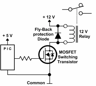
Why don't do it easy and use a MOSFET and a 12V relay. Then you don't need to worry about heat and 5V power consumption. See attached picture sample circuit. You should probably also add a resistor from the output of the PIC to GND to make sure the relay is turn properly off.
Regards, Thomas
2014-06-17 10:04 GMT+02:00 Olav A. Antonsen <olav@ansit.no>:
Seems like most car phone chargers uses a MC34063 switchmode-regulator chip that is much more efficient than a 7805. Will strip one out of its casing and give it a try.
For stronger currents I was told to use a UBEC.
--Olav
*From:* ovmsdev-bounces@lists.teslaclub.hk [mailto: ovmsdev-bounces@lists.teslaclub.hk] *On Behalf Of *Mastro Gippo *Sent:* 17. juni 2014 09:38
*To:* OVMS Developers *Subject:* Re: [Ovmsdev] OVMS - HW
Olav, the temperature should not raise that much, as the PCB is dissipating some of the heat. You can just try it and see if it heats up too much (being careful not to blow the fuse, as Mark said), or use your own 7805 slapped to a small heatsink. If you need more power, a car phone charger may be a better choice as it has a more efficient switching supply.
MG
2014-06-17 8:44 GMT+02:00 Olav A. Antonsen <olav@ansit.no>:
100°C/W! 9V * 0.2A = 1.8W => I need to keep the relays closed for 1 hour so it’s going to overheat!
Need to find another solution for feeding the relay module with +5V.
Mastro, any suggestions?
--Olav
*From:* ovmsdev-bounces@lists.teslaclub.hk [mailto: ovmsdev-bounces@lists.teslaclub.hk] *On Behalf Of *Mastro Gippo *Sent:* 17. juni 2014 00:33 *To:* OVMS Developers *Subject:* Re: [Ovmsdev] OVMS - HW
Hi, this is the correct DS: http://www.st.com/web/en/resource/technical/document/datasheet/CD00000444.pd...
for the DPAK package the OVMS is using, you have 8°C/W for the TJ and 100°C/W for TA. (it's a small package!)
Also, you must calc the dissipation thinking about the "dissipated" voltage, so not 5V but (14V-5V) = 9V (worst case).
You should also add some margin, e.g. use 100mA instead of 80mA just to be safe.
Just try it and keep a finger on the IC for a few minutes to see if it overheats, it shouldn't hurt the board.
MG
2014-06-17 0:14 GMT+02:00 Olav A. Antonsen <olav@ansit.no>:
Great video thermal design.
My knowledge on thermal design is only 30 minutes old, but my interpretation of the datasheet gives med
The regulator will reach 23°C/W above ambient.
Running at max 1.5A @ 5V = 7.5W.
23C/W => 172.5°C -> To hot to handle
2 relays @ 80mA each ~ 0.16A @ 5V ~ 0,8W ~ 18.4°C above ambient.
My conclusion is that adding a consumption of 160mA will raise the temperature 18.4°C above ambient. (This comes in addition to the current the OVMS module consumes.
)
Is this correct?
Regards
Olav
*Fra:* ovmsdev-bounces@lists.teslaclub.hk [mailto: ovmsdev-bounces@lists.teslaclub.hk] *På vegne av* Mastro Gippo *Sendt:* 16. juni 2014 23:38
*Til:* OVMS Developers *Emne:* Re: [Ovmsdev] OVMS - HW
The 1.5A is not the whole story; you can watch this: https://www.youtube.com/watch?v=8ruFVmxf0zs
Basically, if you had that 7805 on free air powering your two relays, it would (try to) reach about 170°C above ambient temperature. The PCB is a nice heatsink, but it is shared with the big GSM regulator, and that rises the temperature too.
By all means, experiment!! The 7805 has thermal protection, and you should test your circuit on the bench keeping a finger on the IC to feel if it gets too hot.
You should take care of the increased ripple too, but a small cap should do the trick there.
Regards
MG
2014-06-16 23:09 GMT+02:00 Olav A. Antonsen <olav@ansit.no>:
I got some help from a user on a Norwegian forum who pointed me to
https://raw.githubusercontent.com/openvehicles/Open-Vehicle-Monitoring-Syste...
Looks like a 7805-regulator is supplying the OVMS module with +5V @ 1.5A max.
https://www.sparkfun.com/datasheets/Components/LM7805.pdf
80mA won't be a problem then.
--Olav
*Fra:* ovmsdev-bounces@lists.teslaclub.hk [mailto: ovmsdev-bounces@lists.teslaclub.hk] *På vegne av* Mastro Gippo *Sendt:* 16. juni 2014 23:03 *Til:* OVMS Developers *Emne:* Re: [Ovmsdev] OVMS - HW
It may be a problem to get the 5V from the output of the regulator, but the nice thing about that module is that it is isolated; you can connect your own power supply and be 100% safe. These relays draw about 80mA each (just tested them, I have the same product at home), so if you turn them on one at a time and for short periods of time it should be ok (I don't know a lot about the termal design of the OVMS).
MG
2014-06-16 22:37 GMT+02:00 Olav A. Antonsen <olav@ansit.no>:
Hello
My knowledge of electronics is limited.
As far as I understand the OVMS module is supplied with +12V via the OBD connector. What I don't understand is where the +5V comes from?
https://github.com/openvehicles/Open-Vehicle-Monitoring-System/blob/master/v...
I'm currently trying to control a relay using the RC3 output on the PIC18F2580 as a control signal to a rely on a relay module
http://www.dx.com/p/arduino-2-channel-relay-shield-module-red-144140#.U59Qav... .
The relay module needs to be supplied with +5V to drive the relays, and my plan was to get the +5V from the OVMS module using pin 13 on the HEADER 9X2.
But I'm afraid I might blow something on the OVMS module if the relay module draws to many mA.
Any advice would be appreciated.
--Olav
OvmsDev mailing list OvmsDev@lists.teslaclub.hk http://lists.teslaclub.hk/mailman/listinfo/ovmsdev
OvmsDev mailing list OvmsDev@lists.teslaclub.hk http://lists.teslaclub.hk/mailman/listinfo/ovmsdev
OvmsDev mailing list OvmsDev@lists.teslaclub.hk http://lists.teslaclub.hk/mailman/listinfo/ovmsdev
OvmsDev mailing list OvmsDev@lists.teslaclub.hk http://lists.teslaclub.hk/mailman/listinfo/ovmsdev
OvmsDev mailing list OvmsDev@lists.teslaclub.hk http://lists.teslaclub.hk/mailman/listinfo/ovmsdev