
Design layout. Looks good to me, but open to suggestions... We can make in sets of three PCBs, to keep prices down. Regards, Mark
On 8 Apr 2019, at 12:05 PM, Mark Webb-Johnson <mark@webb-johnson.net> wrote:
A kit of 5 PCBs + SIP edge connectors + mounting hardware, unsoldered, would be about US$15 + shipping. About US$3/board set. With shipping I don’t think this is worth doing with less than 3 or 5 boards per kit.
Would this be useful?
Regards, Mark.
On 7 Apr 2019, at 9:08 PM, Mark Webb-Johnson <mark@webb-johnson.net> wrote:
This is the closest we have today:
<image1.jpeg>
That is a bare modem board, with just the sip connectors. The prototype above is a K-line transceiver.
I think it would be trivial, and cheap, to make up what you show. Perhaps just solder ready pads at 0.1” pitch, then the side sip connectors wired to the first row of pads at each edge. Perhaps 5 PCBs in a kit, with sip edge connectors, unsoldered, in a simple plastic bag.
Does that sound like something useful? If so, I can ask the China guys for some idea of pricing. If it is just the unsoldered pcbs + parts, I don’t think it will be expensive.
Regards, Mark
On 7 Apr 2019, at 4:38 PM, Michael Balzer <dexter@expeedo.de> wrote:
Mark,
do you know of some kind of prototyping board available that fits to our piggy back expansion layout?
Something like this: https://www.robotshop.com/de/de/cytron-arduino-proto-schild.html
Regards, Michael
Am 03.04.19 um 06:48 schrieb Mark Webb-Johnson:
If you have work to do on this DA26 expansion ports, this is pretty cool and well built:
https://www.aliexpress.com/item/26-Pin-D-SUB-DB26-3-Rows-Serial-Parallel-Por...
_______________________________________________ OvmsDev mailing list OvmsDev@lists.openvehicles.com http://lists.openvehicles.com/mailman/listinfo/ovmsdev
-- Michael Balzer * Helkenberger Weg 9 * D-58256 Ennepetal Fon 02333 / 833 5735 * Handy 0176 / 206 989 26 _______________________________________________ OvmsDev mailing list OvmsDev@lists.openvehicles.com http://lists.openvehicles.com/mailman/listinfo/ovmsdev
OvmsDev mailing list OvmsDev@lists.openvehicles.com http://lists.openvehicles.com/mailman/listinfo/ovmsdev
_______________________________________________ OvmsDev mailing list OvmsDev@lists.openvehicles.com http://lists.openvehicles.com/mailman/listinfo/ovmsdev

Both I and my friend (who has a roadster) would like to use the newer/better cell modems. And the extra cost of the module that causes you guys to choose not to mass produce and sell isn't a barrier for us. If bare modem boards were available how hard would it be to populate some with newer cell modems? If everything has exposed pins I'm sure I could do it (I've built a few small boards of my own design and have a stereo microscope). But if there are any BGA involved I wouldn't want to attempt it. (Looking at the pictures on fasttech.com I don't think this is will be a problem.) And at some point I also want to use ovms in my J1850/Class 2 C6 Corvette. I'm very familiar with the J1850 side. But I don't know which approach would be best: either adding a custom board internally or making an external j1850 to can bridge (could it plug into the HUD port?) Craig
Craig, What is the reason to use newer/better cell modems? I presume you are talking about 4G, but given that 3G is currently well supported, and we have a 115200bps link to the modem, what is the purpose? Our modem board design does follow SIMCOM’s recommendations for layout compatibility, and you may be able to find a 4G SIMCOM module that is a drop-in replacement for the SIM5360 we use. We did make a prototype for the 7xxx series 4G NB iot chips, but that was a different size and the layout was quite different. Perhaps the pure LTE 7100/7500/7600 would work better? The modem board is relatively complex and tightly packed. For example, it requires it’s own power supply circuitry as it doesn’t operate from either 3.3v or 5.0v (I think it uses 3.6v, but can’t remember exactly). We don’t use BGA, but it is surface mount technology. Overall, it is probably easier to just take our schematics and board layouts and make your own. The J1850 may be simpler. You could use one of these new prototyping boards to implement it relatively easily. You could also do it externally off the DA26 port, but the I/O is more flexible in the internal expansion area. Regards, Mark.
On 18 Apr 2019, at 5:03 AM, Craig Leres <leres@xse.com> wrote:
Both I and my friend (who has a roadster) would like to use the newer/better cell modems. And the extra cost of the module that causes you guys to choose not to mass produce and sell isn't a barrier for us.
If bare modem boards were available how hard would it be to populate some with newer cell modems? If everything has exposed pins I'm sure I could do it (I've built a few small boards of my own design and have a stereo microscope). But if there are any BGA involved I wouldn't want to attempt it. (Looking at the pictures on fasttech.com I don't think this is will be a problem.)
And at some point I also want to use ovms in my J1850/Class 2 C6 Corvette. I'm very familiar with the J1850 side. But I don't know which approach would be best: either adding a custom board internally or making an external j1850 to can bridge (could it plug into the HUD port?)
Craig
On 2019-04-17 16:24, Mark Webb-Johnson wrote:
What is the reason to use newer/better cell modems? I presume you are talking about 4G, but given that 3G is currently well supported, and we have a 115200bps link to the modem, what is the purpose?
My friend with the roadster says he gets really sketchy cell coverage where he parks the car at home. The last time we talked about it it seemed like it shouldn't be difficult to hand build a couple ovms modem boards with a different cell module.
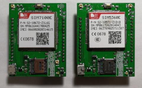
Our modem board design does follow SIMCOM’s recommendations for layout compatibility, and you may be able to find a 4G SIMCOM module that is a drop-in replacement for the SIM5360 we use. We did make a prototype for the 7xxx series 4G NB iot chips, but that was a different size and the layout was quite different. Perhaps the pure LTE 7100/7500/7600 would work better
The modem board is relatively complex and tightly packed. For example, it requires it’s own power supply circuitry as it doesn’t operate from either 3.3v or 5.0v (I think it uses 3.6v, but can’t remember exactly). We don’t use BGA, but it is surface mount technology. Overall, it is probably easier to just take our schematics and board layouts and make your own.
I think that's beyond what we were looking to get into. But if it's possible to buy some bare boards and you can recommend likely parts to try (SIM7600E?) I'm willing to give it a go.
The J1850 may be simpler. You could use one of these new prototyping boards to implement it relatively easily. You could also do it externally off the DA26 port, but the I/O is more flexible in the internal expansion area.
Internal sounds like the way for me to go. Looks like you can expect to immediately sell some of these boards once they're available!
I personally prefer isolated. Allows for the most flexibility. But I have seen designs with connected rows as well.
I'm the opposite, I like rows. And if I want to do something finer grain I cut traces with a scalpel. Here's my favorite proto board: https://www.mouser.com/datasheet/2/58/BPS-DAT-(POW3U)-Datasheet-932637.pdf Anyway my J1850 circuit is pretty simple (I have a handful of HIP7010 and HIP7020 chips, one dip and on sop14) so whatever you come up with will be fine. Craig
FYI: I found this old picture from a year ago: It would seem to indicate a SIM7100E will fit. No idea about software compatibility (the SIMCOM driver), etc - we never proceeded with using it once we found out the price. Regards, Mark.
On 19 Apr 2019, at 12:48 AM, Craig Leres <leres@xse.com> wrote:
On 2019-04-17 16:24, Mark Webb-Johnson wrote:
What is the reason to use newer/better cell modems? I presume you are talking about 4G, but given that 3G is currently well supported, and we have a 115200bps link to the modem, what is the purpose?
My friend with the roadster says he gets really sketchy cell coverage where he parks the car at home. The last time we talked about it it seemed like it shouldn't be difficult to hand build a couple ovms modem boards with a different cell module.
Our modem board design does follow SIMCOM’s recommendations for layout compatibility, and you may be able to find a 4G SIMCOM module that is a drop-in replacement for the SIM5360 we use. We did make a prototype for the 7xxx series 4G NB iot chips, but that was a different size and the layout was quite different. Perhaps the pure LTE 7100/7500/7600 would work better
The modem board is relatively complex and tightly packed. For example, it requires it’s own power supply circuitry as it doesn’t operate from either 3.3v or 5.0v (I think it uses 3.6v, but can’t remember exactly). We don’t use BGA, but it is surface mount technology. Overall, it is probably easier to just take our schematics and board layouts and make your own.
I think that's beyond what we were looking to get into. But if it's possible to buy some bare boards and you can recommend likely parts to try (SIM7600E?) I'm willing to give it a go.
The J1850 may be simpler. You could use one of these new prototyping boards to implement it relatively easily. You could also do it externally off the DA26 port, but the I/O is more flexible in the internal expansion area.
Internal sounds like the way for me to go. Looks like you can expect to immediately sell some of these boards once they're available!
I personally prefer isolated. Allows for the most flexibility. But I have seen designs with connected rows as well.
I'm the opposite, I like rows. And if I want to do something finer grain I cut traces with a scalpel.
Here's my favorite proto board:
https://www.mouser.com/datasheet/2/58/BPS-DAT-(POW3U)-Datasheet-932637.pdf
Anyway my J1850 circuit is pretty simple (I have a handful of HIP7010 and HIP7020 chips, one dip and on sop14) so whatever you come up with will be fine.
Craig
It seems the attachments were messed up, so attaching again… Regards, Mark.
On 17 Apr 2019, at 10:07 PM, Mark Webb-Johnson <mark@webb-johnson.net> wrote:
Design layout. Looks good to me, but open to suggestions...
We can make in sets of three PCBs, to keep prices down.
Regards, Mark
On 8 Apr 2019, at 12:05 PM, Mark Webb-Johnson <mark@webb-johnson.net <mailto:mark@webb-johnson.net>> wrote:
A kit of 5 PCBs + SIP edge connectors + mounting hardware, unsoldered, would be about US$15 + shipping. About US$3/board set. With shipping I don’t think this is worth doing with less than 3 or 5 boards per kit.
Would this be useful?
Regards, Mark.
On 7 Apr 2019, at 9:08 PM, Mark Webb-Johnson <mark@webb-johnson.net <mailto:mark@webb-johnson.net>> wrote:
This is the closest we have today:
<image1.jpeg>
That is a bare modem board, with just the sip connectors. The prototype above is a K-line transceiver.
I think it would be trivial, and cheap, to make up what you show. Perhaps just solder ready pads at 0.1” pitch, then the side sip connectors wired to the first row of pads at each edge. Perhaps 5 PCBs in a kit, with sip edge connectors, unsoldered, in a simple plastic bag.
Does that sound like something useful? If so, I can ask the China guys for some idea of pricing. If it is just the unsoldered pcbs + parts, I don’t think it will be expensive.
Regards, Mark
On 7 Apr 2019, at 4:38 PM, Michael Balzer <dexter@expeedo.de <mailto:dexter@expeedo.de>> wrote:
Mark,
do you know of some kind of prototyping board available that fits to our piggy back expansion layout?
Something like this: https://www.robotshop.com/de/de/cytron-arduino-proto-schild.html <https://www.robotshop.com/de/de/cytron-arduino-proto-schild.html>
Regards, Michael
Am 03.04.19 um 06:48 schrieb Mark Webb-Johnson:
If you have work to do on this DA26 expansion ports, this is pretty cool and well built:
https://www.aliexpress.com/item/26-Pin-D-SUB-DB26-3-Rows-Serial-Parallel-Por... <https://www.aliexpress.com/item/26-Pin-D-SUB-DB26-3-Rows-Serial-Parallel-Port-Serial-Shellless-Male-And-Female-Connector/32886738786.html?spm=a2g0s.9042311.0.0.20924c4dg34EEU>
_______________________________________________ OvmsDev mailing list OvmsDev@lists.openvehicles.com <mailto:OvmsDev@lists.openvehicles.com> http://lists.openvehicles.com/mailman/listinfo/ovmsdev <http://lists.openvehicles.com/mailman/listinfo/ovmsdev>
-- Michael Balzer * Helkenberger Weg 9 * D-58256 Ennepetal Fon 02333 / 833 5735 * Handy 0176 / 206 989 26 _______________________________________________ OvmsDev mailing list OvmsDev@lists.openvehicles.com <mailto:OvmsDev@lists.openvehicles.com> http://lists.openvehicles.com/mailman/listinfo/ovmsdev <http://lists.openvehicles.com/mailman/listinfo/ovmsdev>
OvmsDev mailing list OvmsDev@lists.openvehicles.com <mailto:OvmsDev@lists.openvehicles.com> http://lists.openvehicles.com/mailman/listinfo/ovmsdev <http://lists.openvehicles.com/mailman/listinfo/ovmsdev>
_______________________________________________ OvmsDev mailing list OvmsDev@lists.openvehicles.com <mailto:OvmsDev@lists.openvehicles.com> http://lists.openvehicles.com/mailman/listinfo/ovmsdev <http://lists.openvehicles.com/mailman/listinfo/ovmsdev>
_______________________________________________ OvmsDev mailing list OvmsDev@lists.openvehicles.com http://lists.openvehicles.com/mailman/listinfo/ovmsdev

Put me down for package - I've been thinking about driving a handful of relays for various things, and have been thinking about having a small number of boards like this done - it's pretty much impossible to find a generic prototype board with 2mm pitch holes... Although I'm no designer.... - What about extending the 12V rail all the way to the end of column 16, parallel to the ground rail? - Currently, all the holes are isolated. Would there be any benefit to connecting the holes in each row in groups of 3 or 4? Brian. On Wed., Apr. 17, 2019, 19:37 Mark Webb-Johnson, <mark@webb-johnson.net> wrote:
It seems the attachments were messed up, so attaching again…
Regards, Mark.
On 17 Apr 2019, at 10:07 PM, Mark Webb-Johnson <mark@webb-johnson.net> wrote:
Design layout. Looks good to me, but open to suggestions...
We can make in sets of three PCBs, to keep prices down.
Regards, Mark
On 8 Apr 2019, at 12:05 PM, Mark Webb-Johnson <mark@webb-johnson.net> wrote:
A kit of 5 PCBs + SIP edge connectors + mounting hardware, unsoldered, would be about US$15 + shipping. About US$3/board set. With shipping I don’t think this is worth doing with less than 3 or 5 boards per kit.
Would this be useful?
Regards, Mark.
On 7 Apr 2019, at 9:08 PM, Mark Webb-Johnson <mark@webb-johnson.net> wrote:
This is the closest we have today:
<image1.jpeg>
That is a bare modem board, with just the sip connectors. The prototype above is a K-line transceiver.
I think it would be trivial, and cheap, to make up what you show. Perhaps just solder ready pads at 0.1” pitch, then the side sip connectors wired to the first row of pads at each edge. Perhaps 5 PCBs in a kit, with sip edge connectors, unsoldered, in a simple plastic bag.
Does that sound like something useful? If so, I can ask the China guys for some idea of pricing. If it is just the unsoldered pcbs + parts, I don’t think it will be expensive.
Regards, Mark
On 7 Apr 2019, at 4:38 PM, Michael Balzer <dexter@expeedo.de> wrote:
Mark,
do you know of some kind of prototyping board available that fits to our piggy back expansion layout?
Something like this: https://www.robotshop.com/de/de/cytron-arduino-proto-schild.html
Regards, Michael
Am 03.04.19 um 06:48 schrieb Mark Webb-Johnson:
If you have work to do on this DA26 expansion ports, this is pretty cool and well built:
https://www.aliexpress.com/item/26-Pin-D-SUB-DB26-3-Rows-Serial-Parallel-Por...
_______________________________________________ OvmsDev mailing listOvmsDev@lists.openvehicles.comhttp://lists.openvehicles.com/mailman/listinfo/ovmsdev
-- Michael Balzer * Helkenberger Weg 9 * D-58256 Ennepetal Fon 02333 / 833 5735 * Handy 0176 / 206 989 26
_______________________________________________ OvmsDev mailing list OvmsDev@lists.openvehicles.com http://lists.openvehicles.com/mailman/listinfo/ovmsdev
_______________________________________________ OvmsDev mailing list OvmsDev@lists.openvehicles.com http://lists.openvehicles.com/mailman/listinfo/ovmsdev
_______________________________________________ OvmsDev mailing list OvmsDev@lists.openvehicles.com http://lists.openvehicles.com/mailman/listinfo/ovmsdev
_______________________________________________ OvmsDev mailing list OvmsDev@lists.openvehicles.com http://lists.openvehicles.com/mailman/listinfo/ovmsdev
_______________________________________________ OvmsDev mailing list OvmsDev@lists.openvehicles.com http://lists.openvehicles.com/mailman/listinfo/ovmsdev
- What about extending the 12V rail all the way to the end of column 16, parallel to the ground rail?
Would most projects require 12V? I thought 3.3v and GND would be the most useful? We could extend the 12V, but I worry it is a little close to that GND batch.
- Currently, all the holes are isolated. Would there be any benefit to connecting the holes in each row in groups of 3 or 4?
I personally prefer isolated. Allows for the most flexibility. But I have seen designs with connected rows as well. The current design is intended to maximise the number of holes available. Designer has said he is trying to tidy it up now, and then will make a few samples to see how it looks/fits. Regards, Mark.
On 18 Apr 2019, at 11:18 AM, Brian Greenberg <grnbrg@grnbrg.org> wrote:
Put me down for package - I've been thinking about driving a handful of relays for various things, and have been thinking about having a small number of boards like this done - it's pretty much impossible to find a generic prototype board with 2mm pitch holes...
Although I'm no designer....
- What about extending the 12V rail all the way to the end of column 16, parallel to the ground rail? - Currently, all the holes are isolated. Would there be any benefit to connecting the holes in each row in groups of 3 or 4?
Brian.
On Wed., Apr. 17, 2019, 19:37 Mark Webb-Johnson, <mark@webb-johnson.net <mailto:mark@webb-johnson.net>> wrote: It seems the attachments were messed up, so attaching again…
Regards, Mark.
On 17 Apr 2019, at 10:07 PM, Mark Webb-Johnson <mark@webb-johnson.net <mailto:mark@webb-johnson.net>> wrote:
Design layout. Looks good to me, but open to suggestions...
We can make in sets of three PCBs, to keep prices down.
Regards, Mark
On 8 Apr 2019, at 12:05 PM, Mark Webb-Johnson <mark@webb-johnson.net <mailto:mark@webb-johnson.net>> wrote:
A kit of 5 PCBs + SIP edge connectors + mounting hardware, unsoldered, would be about US$15 + shipping. About US$3/board set. With shipping I don’t think this is worth doing with less than 3 or 5 boards per kit.
Would this be useful?
Regards, Mark.
On 7 Apr 2019, at 9:08 PM, Mark Webb-Johnson <mark@webb-johnson.net <mailto:mark@webb-johnson.net>> wrote:
This is the closest we have today:
<image1.jpeg>
That is a bare modem board, with just the sip connectors. The prototype above is a K-line transceiver.
I think it would be trivial, and cheap, to make up what you show. Perhaps just solder ready pads at 0.1” pitch, then the side sip connectors wired to the first row of pads at each edge. Perhaps 5 PCBs in a kit, with sip edge connectors, unsoldered, in a simple plastic bag.
Does that sound like something useful? If so, I can ask the China guys for some idea of pricing. If it is just the unsoldered pcbs + parts, I don’t think it will be expensive.
Regards, Mark
On 7 Apr 2019, at 4:38 PM, Michael Balzer <dexter@expeedo.de <mailto:dexter@expeedo.de>> wrote:
Mark,
do you know of some kind of prototyping board available that fits to our piggy back expansion layout?
Something like this: https://www.robotshop.com/de/de/cytron-arduino-proto-schild.html <https://www.robotshop.com/de/de/cytron-arduino-proto-schild.html>
Regards, Michael
Am 03.04.19 um 06:48 schrieb Mark Webb-Johnson:
If you have work to do on this DA26 expansion ports, this is pretty cool and well built:
https://www.aliexpress.com/item/26-Pin-D-SUB-DB26-3-Rows-Serial-Parallel-Por... <https://www.aliexpress.com/item/26-Pin-D-SUB-DB26-3-Rows-Serial-Parallel-Port-Serial-Shellless-Male-And-Female-Connector/32886738786.html?spm=a2g0s.9042311.0.0.20924c4dg34EEU>
_______________________________________________ OvmsDev mailing list OvmsDev@lists.openvehicles.com <mailto:OvmsDev@lists.openvehicles.com> http://lists.openvehicles.com/mailman/listinfo/ovmsdev <http://lists.openvehicles.com/mailman/listinfo/ovmsdev>
-- Michael Balzer * Helkenberger Weg 9 * D-58256 Ennepetal Fon 02333 / 833 5735 * Handy 0176 / 206 989 26 _______________________________________________ OvmsDev mailing list OvmsDev@lists.openvehicles.com <mailto:OvmsDev@lists.openvehicles.com> http://lists.openvehicles.com/mailman/listinfo/ovmsdev <http://lists.openvehicles.com/mailman/listinfo/ovmsdev>
OvmsDev mailing list OvmsDev@lists.openvehicles.com <mailto:OvmsDev@lists.openvehicles.com> http://lists.openvehicles.com/mailman/listinfo/ovmsdev <http://lists.openvehicles.com/mailman/listinfo/ovmsdev>
_______________________________________________ OvmsDev mailing list OvmsDev@lists.openvehicles.com <mailto:OvmsDev@lists.openvehicles.com> http://lists.openvehicles.com/mailman/listinfo/ovmsdev <http://lists.openvehicles.com/mailman/listinfo/ovmsdev>
_______________________________________________ OvmsDev mailing list OvmsDev@lists.openvehicles.com <mailto:OvmsDev@lists.openvehicles.com> http://lists.openvehicles.com/mailman/listinfo/ovmsdev <http://lists.openvehicles.com/mailman/listinfo/ovmsdev>
_______________________________________________ OvmsDev mailing list OvmsDev@lists.openvehicles.com <mailto:OvmsDev@lists.openvehicles.com> http://lists.openvehicles.com/mailman/listinfo/ovmsdev <http://lists.openvehicles.com/mailman/listinfo/ovmsdev> _______________________________________________ OvmsDev mailing list OvmsDev@lists.openvehicles.com http://lists.openvehicles.com/mailman/listinfo/ovmsdev

Mark, that looks very good. Not sure about general demand, but I think we should have this to enable simple custom hardware I/O extensions. For the Twizy, I was thinking about adding logic to control the brake light from the module. The Twizy does not activate the brake light on recuperation, as that's normally (untuned) not very strong. But a tuned Twizy allows one pedal driving, so needs this. Looking at our case I also think one custom extension board should fit on top of the modem. Regards, Michael Am 18.04.19 um 02:36 schrieb Mark Webb-Johnson:
It seems the attachments were messed up, so attaching again…
Regards, Mark.
On 17 Apr 2019, at 10:07 PM, Mark Webb-Johnson <mark@webb-johnson.net <mailto:mark@webb-johnson.net>> wrote:
Design layout. Looks good to me, but open to suggestions...
We can make in sets of three PCBs, to keep prices down.
Regards, Mark
On 8 Apr 2019, at 12:05 PM, Mark Webb-Johnson <mark@webb-johnson.net <mailto:mark@webb-johnson.net>> wrote:
A kit of 5 PCBs + SIP edge connectors + mounting hardware, unsoldered, would be about US$15 + shipping. About US$3/board set. With shipping I don’t think this is worth doing with less than 3 or 5 boards per kit.
Would this be useful?
Regards, Mark.
On 7 Apr 2019, at 9:08 PM, Mark Webb-Johnson <mark@webb-johnson.net <mailto:mark@webb-johnson.net>> wrote:
This is the closest we have today:
<image1.jpeg>
That is a bare modem board, with just the sip connectors. The prototype above is a K-line transceiver.
I think it would be trivial, and cheap, to make up what you show. Perhaps just solder ready pads at 0.1” pitch, then the side sip connectors wired to the first row of pads at each edge. Perhaps 5 PCBs in a kit, with sip edge connectors, unsoldered, in a simple plastic bag.
Does that sound like something useful? If so, I can ask the China guys for some idea of pricing. If it is just the unsoldered pcbs + parts, I don’t think it will be expensive.
Regards, Mark
On 7 Apr 2019, at 4:38 PM, Michael Balzer <dexter@expeedo.de <mailto:dexter@expeedo.de>> wrote:
Mark,
do you know of some kind of prototyping board available that fits to our piggy back expansion layout?
Something like this: https://www.robotshop.com/de/de/cytron-arduino-proto-schild.html
Regards, Michael
Am 03.04.19 um 06:48 schrieb Mark Webb-Johnson:
If you have work to do on this DA26 expansion ports, this is pretty cool and well built:
https://www.aliexpress.com/item/26-Pin-D-SUB-DB26-3-Rows-Serial-Parallel-Por...
_______________________________________________ OvmsDev mailing list OvmsDev@lists.openvehicles.com http://lists.openvehicles.com/mailman/listinfo/ovmsdev
-- Michael Balzer * Helkenberger Weg 9 * D-58256 Ennepetal Fon 02333 / 833 5735 * Handy 0176 / 206 989 26 _______________________________________________ OvmsDev mailing list OvmsDev@lists.openvehicles.com <mailto:OvmsDev@lists.openvehicles.com> http://lists.openvehicles.com/mailman/listinfo/ovmsdev
OvmsDev mailing list OvmsDev@lists.openvehicles.com <mailto:OvmsDev@lists.openvehicles.com> http://lists.openvehicles.com/mailman/listinfo/ovmsdev
_______________________________________________ OvmsDev mailing list OvmsDev@lists.openvehicles.com <mailto:OvmsDev@lists.openvehicles.com> http://lists.openvehicles.com/mailman/listinfo/ovmsdev
_______________________________________________ OvmsDev mailing list OvmsDev@lists.openvehicles.com <mailto:OvmsDev@lists.openvehicles.com> http://lists.openvehicles.com/mailman/listinfo/ovmsdev
_______________________________________________ OvmsDev mailing list OvmsDev@lists.openvehicles.com http://lists.openvehicles.com/mailman/listinfo/ovmsdev
-- Michael Balzer * Helkenberger Weg 9 * D-58256 Ennepetal Fon 02333 / 833 5735 * Handy 0176 / 206 989 26

The Trio (Mitsubishi I-Miev and clones) does not activate the brake light on recuperation on 2105 and older models, if this is work is very impressive. Michael Balzer <dexter@expeedo.de> ezt írta (időpont: 2019. ápr. 18., Cs, 23:08):
Mark,
that looks very good. Not sure about general demand, but I think we should have this to enable simple custom hardware I/O extensions.
For the Twizy, I was thinking about adding logic to control the brake light from the module. The Twizy does not activate the brake light on recuperation, as that's normally (untuned) not very strong. But a tuned Twizy allows one pedal driving, so needs this.
Looking at our case I also think one custom extension board should fit on top of the modem.
Regards, Michael
Am 18.04.19 um 02:36 schrieb Mark Webb-Johnson:
It seems the attachments were messed up, so attaching again…
Regards, Mark.
On 17 Apr 2019, at 10:07 PM, Mark Webb-Johnson <mark@webb-johnson.net> wrote:
Design layout. Looks good to me, but open to suggestions...
We can make in sets of three PCBs, to keep prices down.
Regards, Mark
On 8 Apr 2019, at 12:05 PM, Mark Webb-Johnson <mark@webb-johnson.net> wrote:
A kit of 5 PCBs + SIP edge connectors + mounting hardware, unsoldered, would be about US$15 + shipping. About US$3/board set. With shipping I don’t think this is worth doing with less than 3 or 5 boards per kit.
Would this be useful?
Regards, Mark.
On 7 Apr 2019, at 9:08 PM, Mark Webb-Johnson <mark@webb-johnson.net> wrote:
This is the closest we have today:
<image1.jpeg>
That is a bare modem board, with just the sip connectors. The prototype above is a K-line transceiver.
I think it would be trivial, and cheap, to make up what you show. Perhaps just solder ready pads at 0.1” pitch, then the side sip connectors wired to the first row of pads at each edge. Perhaps 5 PCBs in a kit, with sip edge connectors, unsoldered, in a simple plastic bag.
Does that sound like something useful? If so, I can ask the China guys for some idea of pricing. If it is just the unsoldered pcbs + parts, I don’t think it will be expensive.
Regards, Mark
On 7 Apr 2019, at 4:38 PM, Michael Balzer <dexter@expeedo.de> wrote:
Mark,
do you know of some kind of prototyping board available that fits to our piggy back expansion layout?
Something like this: https://www.robotshop.com/de/de/cytron-arduino-proto-schild.html
Regards, Michael
Am 03.04.19 um 06:48 schrieb Mark Webb-Johnson:
If you have work to do on this DA26 expansion ports, this is pretty cool and well built:
https://www.aliexpress.com/item/26-Pin-D-SUB-DB26-3-Rows-Serial-Parallel-Por...
_______________________________________________ OvmsDev mailing listOvmsDev@lists.openvehicles.comhttp://lists.openvehicles.com/mailman/listinfo/ovmsdev
-- Michael Balzer * Helkenberger Weg 9 * D-58256 Ennepetal Fon 02333 / 833 5735 * Handy 0176 / 206 989 26
_______________________________________________ OvmsDev mailing list OvmsDev@lists.openvehicles.com http://lists.openvehicles.com/mailman/listinfo/ovmsdev
_______________________________________________ OvmsDev mailing list OvmsDev@lists.openvehicles.com http://lists.openvehicles.com/mailman/listinfo/ovmsdev
_______________________________________________ OvmsDev mailing list OvmsDev@lists.openvehicles.com http://lists.openvehicles.com/mailman/listinfo/ovmsdev
_______________________________________________ OvmsDev mailing list OvmsDev@lists.openvehicles.com http://lists.openvehicles.com/mailman/listinfo/ovmsdev
_______________________________________________ OvmsDev mailing listOvmsDev@lists.openvehicles.comhttp://lists.openvehicles.com/mailman/listinfo/ovmsdev
-- Michael Balzer * Helkenberger Weg 9 * D-58256 Ennepetal Fon 02333 / 833 5735 * Handy 0176 / 206 989 26
_______________________________________________ OvmsDev mailing list OvmsDev@lists.openvehicles.com http://lists.openvehicles.com/mailman/listinfo/ovmsdev
-- Üdvözlettel: Kovács Tamás
As the Mitsubishi code also reads battery current/power level from CAN, it would be trivial to add the same logic there. Am 19.04.19 um 06:52 schrieb Tamás Kovács:
The Trio (Mitsubishi I-Miev and clones) does not activate the brake light on recuperation on 2105 and older models, if this is work is very impressive.
Michael Balzer <dexter@expeedo.de <mailto:dexter@expeedo.de>> ezt írta (időpont: 2019. ápr. 18., Cs, 23:08):
Mark,
that looks very good. Not sure about general demand, but I think we should have this to enable simple custom hardware I/O extensions.
For the Twizy, I was thinking about adding logic to control the brake light from the module. The Twizy does not activate the brake light on recuperation, as that's normally (untuned) not very strong. But a tuned Twizy allows one pedal driving, so needs this.
Looking at our case I also think one custom extension board should fit on top of the modem.
Regards, Michael
Am 18.04.19 um 02:36 schrieb Mark Webb-Johnson:
It seems the attachments were messed up, so attaching again…
Regards, Mark.
On 17 Apr 2019, at 10:07 PM, Mark Webb-Johnson <mark@webb-johnson.net <mailto:mark@webb-johnson.net>> wrote:
Design layout. Looks good to me, but open to suggestions...
We can make in sets of three PCBs, to keep prices down.
Regards, Mark
On 8 Apr 2019, at 12:05 PM, Mark Webb-Johnson <mark@webb-johnson.net <mailto:mark@webb-johnson.net>> wrote:
A kit of 5 PCBs + SIP edge connectors + mounting hardware, unsoldered, would be about US$15 + shipping. About US$3/board set. With shipping I don’t think this is worth doing with less than 3 or 5 boards per kit.
Would this be useful?
Regards, Mark.
On 7 Apr 2019, at 9:08 PM, Mark Webb-Johnson <mark@webb-johnson.net <mailto:mark@webb-johnson.net>> wrote:
This is the closest we have today:
<image1.jpeg>
That is a bare modem board, with just the sip connectors. The prototype above is a K-line transceiver.
I think it would be trivial, and cheap, to make up what you show. Perhaps just solder ready pads at 0.1” pitch, then the side sip connectors wired to the first row of pads at each edge. Perhaps 5 PCBs in a kit, with sip edge connectors, unsoldered, in a simple plastic bag.
Does that sound like something useful? If so, I can ask the China guys for some idea of pricing. If it is just the unsoldered pcbs + parts, I don’t think it will be expensive.
Regards, Mark
On 7 Apr 2019, at 4:38 PM, Michael Balzer <dexter@expeedo.de <mailto:dexter@expeedo.de>> wrote:
Mark,
do you know of some kind of prototyping board available that fits to our piggy back expansion layout?
Something like this: https://www.robotshop.com/de/de/cytron-arduino-proto-schild.html
Regards, Michael
Am 03.04.19 um 06:48 schrieb Mark Webb-Johnson: > > If you have work to do on this DA26 expansion ports, this is pretty cool and well built: > > https://www.aliexpress.com/item/26-Pin-D-SUB-DB26-3-Rows-Serial-Parallel-Por... > > > > > > > _______________________________________________ > OvmsDev mailing list > OvmsDev@lists.openvehicles.com <mailto:OvmsDev@lists.openvehicles.com> > http://lists.openvehicles.com/mailman/listinfo/ovmsdev
-- Michael Balzer * Helkenberger Weg 9 * D-58256 Ennepetal Fon 02333 / 833 5735 * Handy 0176 / 206 989 26 _______________________________________________ OvmsDev mailing list OvmsDev@lists.openvehicles.com <mailto:OvmsDev@lists.openvehicles.com> http://lists.openvehicles.com/mailman/listinfo/ovmsdev
_______________________________________________ OvmsDev mailing list OvmsDev@lists.openvehicles.com <mailto:OvmsDev@lists.openvehicles.com> http://lists.openvehicles.com/mailman/listinfo/ovmsdev
_______________________________________________ OvmsDev mailing list OvmsDev@lists.openvehicles.com <mailto:OvmsDev@lists.openvehicles.com> http://lists.openvehicles.com/mailman/listinfo/ovmsdev
_______________________________________________ OvmsDev mailing list OvmsDev@lists.openvehicles.com <mailto:OvmsDev@lists.openvehicles.com> http://lists.openvehicles.com/mailman/listinfo/ovmsdev
_______________________________________________ OvmsDev mailing list OvmsDev@lists.openvehicles.com <mailto:OvmsDev@lists.openvehicles.com> http://lists.openvehicles.com/mailman/listinfo/ovmsdev
-- Michael Balzer * Helkenberger Weg 9 * D-58256 Ennepetal Fon 02333 / 833 5735 * Handy 0176 / 206 989 26
_______________________________________________ OvmsDev mailing list OvmsDev@lists.openvehicles.com <mailto:OvmsDev@lists.openvehicles.com> http://lists.openvehicles.com/mailman/listinfo/ovmsdev
-- Üdvözlettel: Kovács Tamás
_______________________________________________ OvmsDev mailing list OvmsDev@lists.openvehicles.com http://lists.openvehicles.com/mailman/listinfo/ovmsdev
-- Michael Balzer * Helkenberger Weg 9 * D-58256 Ennepetal Fon 02333 / 833 5735 * Handy 0176 / 206 989 26
I can add for testing a simple led (with resistor) , same as SimpleConsole (twizy OVMS V2), to show car is recuperating, connected to DA26 external expansion port? Michael Balzer <dexter@expeedo.de> ezt írta (időpont: 2019. ápr. 19., P, 9:17):
As the Mitsubishi code also reads battery current/power level from CAN, it would be trivial to add the same logic there.
Am 19.04.19 um 06:52 schrieb Tamás Kovács:
The Trio (Mitsubishi I-Miev and clones) does not activate the brake light on recuperation on 2105 and older models, if this is work is very impressive.
Michael Balzer <dexter@expeedo.de> ezt írta (időpont: 2019. ápr. 18., Cs, 23:08):
Mark,
that looks very good. Not sure about general demand, but I think we should have this to enable simple custom hardware I/O extensions.
For the Twizy, I was thinking about adding logic to control the brake light from the module. The Twizy does not activate the brake light on recuperation, as that's normally (untuned) not very strong. But a tuned Twizy allows one pedal driving, so needs this.
Looking at our case I also think one custom extension board should fit on top of the modem.
Regards, Michael
Am 18.04.19 um 02:36 schrieb Mark Webb-Johnson:
It seems the attachments were messed up, so attaching again…
Regards, Mark.
On 17 Apr 2019, at 10:07 PM, Mark Webb-Johnson <mark@webb-johnson.net> wrote:
Design layout. Looks good to me, but open to suggestions...
We can make in sets of three PCBs, to keep prices down.
Regards, Mark
On 8 Apr 2019, at 12:05 PM, Mark Webb-Johnson <mark@webb-johnson.net> wrote:
A kit of 5 PCBs + SIP edge connectors + mounting hardware, unsoldered, would be about US$15 + shipping. About US$3/board set. With shipping I don’t think this is worth doing with less than 3 or 5 boards per kit.
Would this be useful?
Regards, Mark.
On 7 Apr 2019, at 9:08 PM, Mark Webb-Johnson <mark@webb-johnson.net> wrote:
This is the closest we have today:
<image1.jpeg>
That is a bare modem board, with just the sip connectors. The prototype above is a K-line transceiver.
I think it would be trivial, and cheap, to make up what you show. Perhaps just solder ready pads at 0.1” pitch, then the side sip connectors wired to the first row of pads at each edge. Perhaps 5 PCBs in a kit, with sip edge connectors, unsoldered, in a simple plastic bag.
Does that sound like something useful? If so, I can ask the China guys for some idea of pricing. If it is just the unsoldered pcbs + parts, I don’t think it will be expensive.
Regards, Mark
On 7 Apr 2019, at 4:38 PM, Michael Balzer <dexter@expeedo.de> wrote:
Mark,
do you know of some kind of prototyping board available that fits to our piggy back expansion layout?
Something like this: https://www.robotshop.com/de/de/cytron-arduino-proto-schild.html
Regards, Michael
Am 03.04.19 um 06:48 schrieb Mark Webb-Johnson:
If you have work to do on this DA26 expansion ports, this is pretty cool and well built:
https://www.aliexpress.com/item/26-Pin-D-SUB-DB26-3-Rows-Serial-Parallel-Por...
_______________________________________________ OvmsDev mailing listOvmsDev@lists.openvehicles.comhttp://lists.openvehicles.com/mailman/listinfo/ovmsdev
-- Michael Balzer * Helkenberger Weg 9 * D-58256 Ennepetal Fon 02333 / 833 5735 * Handy 0176 / 206 989 26
_______________________________________________ OvmsDev mailing list OvmsDev@lists.openvehicles.com http://lists.openvehicles.com/mailman/listinfo/ovmsdev
_______________________________________________ OvmsDev mailing list OvmsDev@lists.openvehicles.com http://lists.openvehicles.com/mailman/listinfo/ovmsdev
_______________________________________________ OvmsDev mailing list OvmsDev@lists.openvehicles.com http://lists.openvehicles.com/mailman/listinfo/ovmsdev
_______________________________________________ OvmsDev mailing list OvmsDev@lists.openvehicles.com http://lists.openvehicles.com/mailman/listinfo/ovmsdev
_______________________________________________ OvmsDev mailing listOvmsDev@lists.openvehicles.comhttp://lists.openvehicles.com/mailman/listinfo/ovmsdev
-- Michael Balzer * Helkenberger Weg 9 * D-58256 Ennepetal Fon 02333 / 833 5735 * Handy 0176 / 206 989 26
_______________________________________________ OvmsDev mailing list OvmsDev@lists.openvehicles.com http://lists.openvehicles.com/mailman/listinfo/ovmsdev
-- Üdvözlettel: Kovács Tamás
Sure. You need to route an EGPIO line to the DA26 port. For a first test you can add a simple jumper on expansion port pins 10/12 to route EGPIO_8 to GEP_7 (= pin 21 on DA26). You should then be able to use the "egpio" command to test your LED. EGPIO_1 … _8 labels correspond to MAX7317 ports 2 … 9, so to control EGPIO_8, do: OVMS# egpio output 9 1 # EGPIO_8 on OVMS# egpio output 9 0 # EGPIO_8 off (correct me if I'm wrong, Mark) I wasn't aware there are other cars in need of something like this. I'll think about adding the logic as an option to the vehicle framework, but I can send you some patch to test this on your i-MiEV/clone first. Regards, Michael Am 19.04.19 um 09:24 schrieb Tamás Kovács:
I can add for testing a simple led (with resistor) , same as SimpleConsole (twizy OVMS V2), to show car is recuperating, connected to DA26 external expansion port?
Michael Balzer <dexter@expeedo.de <mailto:dexter@expeedo.de>> ezt írta (időpont: 2019. ápr. 19., P, 9:17):
As the Mitsubishi code also reads battery current/power level from CAN, it would be trivial to add the same logic there.
Am 19.04.19 um 06:52 schrieb Tamás Kovács:
The Trio (Mitsubishi I-Miev and clones) does not activate the brake light on recuperation on 2105 and older models, if this is work is very impressive.
Michael Balzer <dexter@expeedo.de <mailto:dexter@expeedo.de>> ezt írta (időpont: 2019. ápr. 18., Cs, 23:08):
Mark,
that looks very good. Not sure about general demand, but I think we should have this to enable simple custom hardware I/O extensions.
For the Twizy, I was thinking about adding logic to control the brake light from the module. The Twizy does not activate the brake light on recuperation, as that's normally (untuned) not very strong. But a tuned Twizy allows one pedal driving, so needs this.
Looking at our case I also think one custom extension board should fit on top of the modem.
Regards, Michael
Am 18.04.19 um 02:36 schrieb Mark Webb-Johnson:
It seems the attachments were messed up, so attaching again…
Regards, Mark.
On 17 Apr 2019, at 10:07 PM, Mark Webb-Johnson <mark@webb-johnson.net <mailto:mark@webb-johnson.net>> wrote:
Design layout. Looks good to me, but open to suggestions...
We can make in sets of three PCBs, to keep prices down.
Regards, Mark
On 8 Apr 2019, at 12:05 PM, Mark Webb-Johnson <mark@webb-johnson.net <mailto:mark@webb-johnson.net>> wrote:
A kit of 5 PCBs + SIP edge connectors + mounting hardware, unsoldered, would be about US$15 + shipping. About US$3/board set. With shipping I don’t think this is worth doing with less than 3 or 5 boards per kit.
Would this be useful?
Regards, Mark.
On 7 Apr 2019, at 9:08 PM, Mark Webb-Johnson <mark@webb-johnson.net <mailto:mark@webb-johnson.net>> wrote:
This is the closest we have today:
<image1.jpeg>
That is a bare modem board, with just the sip connectors. The prototype above is a K-line transceiver.
I think it would be trivial, and cheap, to make up what you show. Perhaps just solder ready pads at 0.1” pitch, then the side sip connectors wired to the first row of pads at each edge. Perhaps 5 PCBs in a kit, with sip edge connectors, unsoldered, in a simple plastic bag.
Does that sound like something useful? If so, I can ask the China guys for some idea of pricing. If it is just the unsoldered pcbs + parts, I don’t think it will be expensive.
Regards, Mark
On 7 Apr 2019, at 4:38 PM, Michael Balzer <dexter@expeedo.de <mailto:dexter@expeedo.de>> wrote:
> Mark, > > do you know of some kind of prototyping board available that fits to our piggy back expansion layout? > > Something like this: https://www.robotshop.com/de/de/cytron-arduino-proto-schild.html > > Regards, > Michael > > > Am 03.04.19 um 06:48 schrieb Mark Webb-Johnson: >> >> If you have work to do on this DA26 expansion ports, this is pretty cool and well built: >> >> https://www.aliexpress.com/item/26-Pin-D-SUB-DB26-3-Rows-Serial-Parallel-Por... >> >> >> >> >> >> >> _______________________________________________ >> OvmsDev mailing list >> OvmsDev@lists.openvehicles.com <mailto:OvmsDev@lists.openvehicles.com> >> http://lists.openvehicles.com/mailman/listinfo/ovmsdev > > -- > Michael Balzer * Helkenberger Weg 9 * D-58256 Ennepetal > Fon 02333 / 833 5735 * Handy 0176 / 206 989 26 > _______________________________________________ > OvmsDev mailing list > OvmsDev@lists.openvehicles.com <mailto:OvmsDev@lists.openvehicles.com> > http://lists.openvehicles.com/mailman/listinfo/ovmsdev _______________________________________________ OvmsDev mailing list OvmsDev@lists.openvehicles.com <mailto:OvmsDev@lists.openvehicles.com> http://lists.openvehicles.com/mailman/listinfo/ovmsdev
_______________________________________________ OvmsDev mailing list OvmsDev@lists.openvehicles.com <mailto:OvmsDev@lists.openvehicles.com> http://lists.openvehicles.com/mailman/listinfo/ovmsdev
_______________________________________________ OvmsDev mailing list OvmsDev@lists.openvehicles.com <mailto:OvmsDev@lists.openvehicles.com> http://lists.openvehicles.com/mailman/listinfo/ovmsdev
_______________________________________________ OvmsDev mailing list OvmsDev@lists.openvehicles.com <mailto:OvmsDev@lists.openvehicles.com> http://lists.openvehicles.com/mailman/listinfo/ovmsdev
-- Michael Balzer * Helkenberger Weg 9 * D-58256 Ennepetal Fon 02333 / 833 5735 * Handy 0176 / 206 989 26
_______________________________________________ OvmsDev mailing list OvmsDev@lists.openvehicles.com <mailto:OvmsDev@lists.openvehicles.com> http://lists.openvehicles.com/mailman/listinfo/ovmsdev
-- Üdvözlettel: Kovács Tamás
_______________________________________________ OvmsDev mailing list OvmsDev@lists.openvehicles.com <mailto:OvmsDev@lists.openvehicles.com> http://lists.openvehicles.com/mailman/listinfo/ovmsdev
-- Michael Balzer * Helkenberger Weg 9 * D-58256 Ennepetal Fon 02333 / 833 5735 * Handy 0176 / 206 989 26
_______________________________________________ OvmsDev mailing list OvmsDev@lists.openvehicles.com <mailto:OvmsDev@lists.openvehicles.com> http://lists.openvehicles.com/mailman/listinfo/ovmsdev
-- Üdvözlettel: Kovács Tamás
_______________________________________________ OvmsDev mailing list OvmsDev@lists.openvehicles.com http://lists.openvehicles.com/mailman/listinfo/ovmsdev
-- Michael Balzer * Helkenberger Weg 9 * D-58256 Ennepetal Fon 02333 / 833 5735 * Handy 0176 / 206 989 26
Be aware the MAX71317 outputs are open drain, so you need a pull up resistor to e.g. +3.3. According to the data sheet, the current should stay below 6 mA. I've just done a quick test wiring like this: JP1 pin 1 (+3.3) ----- [ 680 Ohms ] ---+--- [ LED ] ----- pin 28 (GND) | pin 12 (EGPIO_8) Works as expected. Regards, Michael Am 19.04.19 um 09:59 schrieb Michael Balzer:
Sure.
You need to route an EGPIO line to the DA26 port. For a first test you can add a simple jumper on expansion port pins 10/12 to route EGPIO_8 to GEP_7 (= pin 21 on DA26).
You should then be able to use the "egpio" command to test your LED. EGPIO_1 … _8 labels correspond to MAX7317 ports 2 … 9, so to control EGPIO_8, do:
OVMS# egpio output 9 1 # EGPIO_8 on OVMS# egpio output 9 0 # EGPIO_8 off
(correct me if I'm wrong, Mark)
I wasn't aware there are other cars in need of something like this. I'll think about adding the logic as an option to the vehicle framework, but I can send you some patch to test this on your i-MiEV/clone first.
Regards, Michael
Am 19.04.19 um 09:24 schrieb Tamás Kovács:
I can add for testing a simple led (with resistor) , same as SimpleConsole (twizy OVMS V2), to show car is recuperating, connected to DA26 external expansion port?
Michael Balzer <dexter@expeedo.de <mailto:dexter@expeedo.de>> ezt írta (időpont: 2019. ápr. 19., P, 9:17):
As the Mitsubishi code also reads battery current/power level from CAN, it would be trivial to add the same logic there.
Am 19.04.19 um 06:52 schrieb Tamás Kovács:
The Trio (Mitsubishi I-Miev and clones) does not activate the brake light on recuperation on 2105 and older models, if this is work is very impressive.
Michael Balzer <dexter@expeedo.de <mailto:dexter@expeedo.de>> ezt írta (időpont: 2019. ápr. 18., Cs, 23:08):
Mark,
that looks very good. Not sure about general demand, but I think we should have this to enable simple custom hardware I/O extensions.
For the Twizy, I was thinking about adding logic to control the brake light from the module. The Twizy does not activate the brake light on recuperation, as that's normally (untuned) not very strong. But a tuned Twizy allows one pedal driving, so needs this.
Looking at our case I also think one custom extension board should fit on top of the modem.
Regards, Michael
Am 18.04.19 um 02:36 schrieb Mark Webb-Johnson:
It seems the attachments were messed up, so attaching again…
Regards, Mark.
On 17 Apr 2019, at 10:07 PM, Mark Webb-Johnson <mark@webb-johnson.net <mailto:mark@webb-johnson.net>> wrote:
Design layout. Looks good to me, but open to suggestions...
We can make in sets of three PCBs, to keep prices down.
Regards, Mark
On 8 Apr 2019, at 12:05 PM, Mark Webb-Johnson <mark@webb-johnson.net <mailto:mark@webb-johnson.net>> wrote:
A kit of 5 PCBs + SIP edge connectors + mounting hardware, unsoldered, would be about US$15 + shipping. About US$3/board set. With shipping I don’t think this is worth doing with less than 3 or 5 boards per kit.
Would this be useful?
Regards, Mark.
> On 7 Apr 2019, at 9:08 PM, Mark Webb-Johnson <mark@webb-johnson.net <mailto:mark@webb-johnson.net>> wrote: > > This is the closest we have today: > > <image1.jpeg> > > That is a bare modem board, with just the sip connectors. The prototype above is a K-line transceiver. > > I think it would be trivial, and cheap, to make up what you show. Perhaps just solder ready pads at 0.1” pitch, then the side sip connectors > wired to the first row of pads at each edge. Perhaps 5 PCBs in a kit, with sip edge connectors, unsoldered, in a simple plastic bag. > > Does that sound like something useful? If so, I can ask the China guys for some idea of pricing. If it is just the unsoldered pcbs + parts, I > don’t think it will be expensive. > > Regards, Mark > > On 7 Apr 2019, at 4:38 PM, Michael Balzer <dexter@expeedo.de <mailto:dexter@expeedo.de>> wrote: > >> Mark, >> >> do you know of some kind of prototyping board available that fits to our piggy back expansion layout? >> >> Something like this: https://www.robotshop.com/de/de/cytron-arduino-proto-schild.html >> >> Regards, >> Michael >> >> >> Am 03.04.19 um 06:48 schrieb Mark Webb-Johnson: >>> >>> If you have work to do on this DA26 expansion ports, this is pretty cool and well built: >>> >>> https://www.aliexpress.com/item/26-Pin-D-SUB-DB26-3-Rows-Serial-Parallel-Por... >>> >>> >>> >>> >>> >>> >>> _______________________________________________ >>> OvmsDev mailing list >>> OvmsDev@lists.openvehicles.com <mailto:OvmsDev@lists.openvehicles.com> >>> http://lists.openvehicles.com/mailman/listinfo/ovmsdev >> >> -- >> Michael Balzer * Helkenberger Weg 9 * D-58256 Ennepetal >> Fon 02333 / 833 5735 * Handy 0176 / 206 989 26 >> _______________________________________________ >> OvmsDev mailing list >> OvmsDev@lists.openvehicles.com <mailto:OvmsDev@lists.openvehicles.com> >> http://lists.openvehicles.com/mailman/listinfo/ovmsdev > _______________________________________________ > OvmsDev mailing list > OvmsDev@lists.openvehicles.com <mailto:OvmsDev@lists.openvehicles.com> > http://lists.openvehicles.com/mailman/listinfo/ovmsdev
_______________________________________________ OvmsDev mailing list OvmsDev@lists.openvehicles.com <mailto:OvmsDev@lists.openvehicles.com> http://lists.openvehicles.com/mailman/listinfo/ovmsdev
_______________________________________________ OvmsDev mailing list OvmsDev@lists.openvehicles.com <mailto:OvmsDev@lists.openvehicles.com> http://lists.openvehicles.com/mailman/listinfo/ovmsdev
_______________________________________________ OvmsDev mailing list OvmsDev@lists.openvehicles.com <mailto:OvmsDev@lists.openvehicles.com> http://lists.openvehicles.com/mailman/listinfo/ovmsdev
-- Michael Balzer * Helkenberger Weg 9 * D-58256 Ennepetal Fon 02333 / 833 5735 * Handy 0176 / 206 989 26
_______________________________________________ OvmsDev mailing list OvmsDev@lists.openvehicles.com <mailto:OvmsDev@lists.openvehicles.com> http://lists.openvehicles.com/mailman/listinfo/ovmsdev
-- Üdvözlettel: Kovács Tamás
_______________________________________________ OvmsDev mailing list OvmsDev@lists.openvehicles.com <mailto:OvmsDev@lists.openvehicles.com> http://lists.openvehicles.com/mailman/listinfo/ovmsdev
-- Michael Balzer * Helkenberger Weg 9 * D-58256 Ennepetal Fon 02333 / 833 5735 * Handy 0176 / 206 989 26
_______________________________________________ OvmsDev mailing list OvmsDev@lists.openvehicles.com <mailto:OvmsDev@lists.openvehicles.com> http://lists.openvehicles.com/mailman/listinfo/ovmsdev
-- Üdvözlettel: Kovács Tamás
_______________________________________________ OvmsDev mailing list OvmsDev@lists.openvehicles.com http://lists.openvehicles.com/mailman/listinfo/ovmsdev
-- Michael Balzer * Helkenberger Weg 9 * D-58256 Ennepetal Fon 02333 / 833 5735 * Handy 0176 / 206 989 26
_______________________________________________ OvmsDev mailing list OvmsDev@lists.openvehicles.com http://lists.openvehicles.com/mailman/listinfo/ovmsdev
-- Michael Balzer * Helkenberger Weg 9 * D-58256 Ennepetal Fon 02333 / 833 5735 * Handy 0176 / 206 989 26
JP1 pin 1 (+3.3) ----- [ 680 Ohms ] ---+--- [ LED ] ----- pin 28 (GND) | pin 12 (EGPIO_8) I can connect a 680Ohm resistor first end to pin1, a second end to pin12, and the led positive side to pin12 and negative to pin28(gnd). Now I have only 470ohm resistor at home, I tested now with a 4V li-ion battery and my red led power is 4mA. I can use this (470Ohm) resistor or buy a 680Ohm. Tomorrow I remove the OVMS module from my car, and create some test, if the resistor (470Ohm) is OK. I used this calculator for led series resistor calculation (I used a red Led): http://ledcalc.com Michael Balzer <dexter@expeedo.de> ezt írta (időpont: 2019. ápr. 20., Szo, 11:16):
Be aware the MAX71317 outputs are open drain, so you need a pull up resistor to e.g. +3.3. According to the data sheet, the current should stay below 6 mA.
I've just done a quick test wiring like this:
JP1 pin 1 (+3.3) ----- [ 680 Ohms ] ---+--- [ LED ] ----- pin 28 (GND) | pin 12 (EGPIO_8)
Works as expected.
Regards, Michael
Am 19.04.19 um 09:59 schrieb Michael Balzer:
Sure.
You need to route an EGPIO line to the DA26 port. For a first test you can add a simple jumper on expansion port pins 10/12 to route EGPIO_8 to GEP_7 (= pin 21 on DA26).
You should then be able to use the "egpio" command to test your LED. EGPIO_1 … _8 labels correspond to MAX7317 ports 2 … 9, so to control EGPIO_8, do:
OVMS# egpio output 9 1 # EGPIO_8 on OVMS# egpio output 9 0 # EGPIO_8 off
(correct me if I'm wrong, Mark)
I wasn't aware there are other cars in need of something like this. I'll think about adding the logic as an option to the vehicle framework, but I can send you some patch to test this on your i-MiEV/clone first.
Regards, Michael
Am 19.04.19 um 09:24 schrieb Tamás Kovács:
I can add for testing a simple led (with resistor) , same as SimpleConsole (twizy OVMS V2), to show car is recuperating, connected to DA26 external expansion port?
Michael Balzer <dexter@expeedo.de> ezt írta (időpont: 2019. ápr. 19., P, 9:17):
As the Mitsubishi code also reads battery current/power level from CAN, it would be trivial to add the same logic there.
Am 19.04.19 um 06:52 schrieb Tamás Kovács:
The Trio (Mitsubishi I-Miev and clones) does not activate the brake light on recuperation on 2105 and older models, if this is work is very impressive.
Michael Balzer <dexter@expeedo.de> ezt írta (időpont: 2019. ápr. 18., Cs, 23:08):
Mark,
that looks very good. Not sure about general demand, but I think we should have this to enable simple custom hardware I/O extensions.
For the Twizy, I was thinking about adding logic to control the brake light from the module. The Twizy does not activate the brake light on recuperation, as that's normally (untuned) not very strong. But a tuned Twizy allows one pedal driving, so needs this.
Looking at our case I also think one custom extension board should fit on top of the modem.
Regards, Michael
Am 18.04.19 um 02:36 schrieb Mark Webb-Johnson:
It seems the attachments were messed up, so attaching again…
Regards, Mark.
On 17 Apr 2019, at 10:07 PM, Mark Webb-Johnson <mark@webb-johnson.net> wrote:
Design layout. Looks good to me, but open to suggestions...
We can make in sets of three PCBs, to keep prices down.
Regards, Mark
On 8 Apr 2019, at 12:05 PM, Mark Webb-Johnson <mark@webb-johnson.net> wrote:
A kit of 5 PCBs + SIP edge connectors + mounting hardware, unsoldered, would be about US$15 + shipping. About US$3/board set. With shipping I don’t think this is worth doing with less than 3 or 5 boards per kit.
Would this be useful?
Regards, Mark.
On 7 Apr 2019, at 9:08 PM, Mark Webb-Johnson <mark@webb-johnson.net> wrote:
This is the closest we have today:
<image1.jpeg>
That is a bare modem board, with just the sip connectors. The prototype above is a K-line transceiver.
I think it would be trivial, and cheap, to make up what you show. Perhaps just solder ready pads at 0.1” pitch, then the side sip connectors wired to the first row of pads at each edge. Perhaps 5 PCBs in a kit, with sip edge connectors, unsoldered, in a simple plastic bag.
Does that sound like something useful? If so, I can ask the China guys for some idea of pricing. If it is just the unsoldered pcbs + parts, I don’t think it will be expensive.
Regards, Mark
On 7 Apr 2019, at 4:38 PM, Michael Balzer <dexter@expeedo.de> wrote:
Mark,
do you know of some kind of prototyping board available that fits to our piggy back expansion layout?
Something like this: https://www.robotshop.com/de/de/cytron-arduino-proto-schild.html
Regards, Michael
Am 03.04.19 um 06:48 schrieb Mark Webb-Johnson:
If you have work to do on this DA26 expansion ports, this is pretty cool and well built:
https://www.aliexpress.com/item/26-Pin-D-SUB-DB26-3-Rows-Serial-Parallel-Por...
_______________________________________________ OvmsDev mailing listOvmsDev@lists.openvehicles.comhttp://lists.openvehicles.com/mailman/listinfo/ovmsdev
-- Michael Balzer * Helkenberger Weg 9 * D-58256 Ennepetal Fon 02333 / 833 5735 * Handy 0176 / 206 989 26
_______________________________________________ OvmsDev mailing list OvmsDev@lists.openvehicles.com http://lists.openvehicles.com/mailman/listinfo/ovmsdev
_______________________________________________ OvmsDev mailing list OvmsDev@lists.openvehicles.com http://lists.openvehicles.com/mailman/listinfo/ovmsdev
_______________________________________________ OvmsDev mailing list OvmsDev@lists.openvehicles.com http://lists.openvehicles.com/mailman/listinfo/ovmsdev
_______________________________________________ OvmsDev mailing list OvmsDev@lists.openvehicles.com http://lists.openvehicles.com/mailman/listinfo/ovmsdev
_______________________________________________ OvmsDev mailing listOvmsDev@lists.openvehicles.comhttp://lists.openvehicles.com/mailman/listinfo/ovmsdev
-- Michael Balzer * Helkenberger Weg 9 * D-58256 Ennepetal Fon 02333 / 833 5735 * Handy 0176 / 206 989 26
_______________________________________________ OvmsDev mailing list OvmsDev@lists.openvehicles.com http://lists.openvehicles.com/mailman/listinfo/ovmsdev
-- Üdvözlettel: Kovács Tamás
_______________________________________________ OvmsDev mailing listOvmsDev@lists.openvehicles.comhttp://lists.openvehicles.com/mailman/listinfo/ovmsdev
-- Michael Balzer * Helkenberger Weg 9 * D-58256 Ennepetal Fon 02333 / 833 5735 * Handy 0176 / 206 989 26
_______________________________________________ OvmsDev mailing list OvmsDev@lists.openvehicles.com http://lists.openvehicles.com/mailman/listinfo/ovmsdev
-- Üdvözlettel: Kovács Tamás
_______________________________________________ OvmsDev mailing listOvmsDev@lists.openvehicles.comhttp://lists.openvehicles.com/mailman/listinfo/ovmsdev
-- Michael Balzer * Helkenberger Weg 9 * D-58256 Ennepetal Fon 02333 / 833 5735 * Handy 0176 / 206 989 26
_______________________________________________ OvmsDev mailing listOvmsDev@lists.openvehicles.comhttp://lists.openvehicles.com/mailman/listinfo/ovmsdev
-- Michael Balzer * Helkenberger Weg 9 * D-58256 Ennepetal Fon 02333 / 833 5735 * Handy 0176 / 206 989 26
_______________________________________________ OvmsDev mailing list OvmsDev@lists.openvehicles.com http://lists.openvehicles.com/mailman/listinfo/ovmsdev
-- Üdvözlettel: Kovács Tamás
If changing vehicle.{h, cpp} framework, I suggest leaving a hook in to allow the vehicle module to override / supplement this. In particular, the brake light may be controllable via can message on some vehicles. You can look at the ext12v circuit to see how to control this. The ext12v system is a switchable 12v line already wired up and available on DA26 expansion. Would be trivial to put an external relay on that to switch brake lights. Regards, Mark.
On 21 Apr 2019, at 1:32 AM, Tamás Kovács <kommykt@gmail.com> wrote:
JP1 pin 1 (+3.3) ----- [ 680 Ohms ] ---+--- [ LED ] ----- pin 28 (GND) | pin 12 (EGPIO_8)
I can connect a 680Ohm resistor first end to pin1, a second end to pin12, and the led positive side to pin12 and negative to pin28(gnd). Now I have only 470ohm resistor at home, I tested now with a 4V li-ion battery and my red led power is 4mA. I can use this (470Ohm) resistor or buy a 680Ohm. Tomorrow I remove the OVMS module from my car, and create some test, if the resistor (470Ohm) is OK. I used this calculator for led series resistor calculation (I used a red Led): http://ledcalc.com <http://ledcalc.com/> Michael Balzer <dexter@expeedo.de <mailto:dexter@expeedo.de>> ezt írta (időpont: 2019. ápr. 20., Szo, 11:16): Be aware the MAX71317 outputs are open drain, so you need a pull up resistor to e.g. +3.3. According to the data sheet, the current should stay below 6 mA.
I've just done a quick test wiring like this:
JP1 pin 1 (+3.3) ----- [ 680 Ohms ] ---+--- [ LED ] ----- pin 28 (GND) | pin 12 (EGPIO_8)
Works as expected.
Regards, Michael
Am 19.04.19 um 09:59 schrieb Michael Balzer:
Sure.
You need to route an EGPIO line to the DA26 port. For a first test you can add a simple jumper on expansion port pins 10/12 to route EGPIO_8 to GEP_7 (= pin 21 on DA26).
You should then be able to use the "egpio" command to test your LED. EGPIO_1 … _8 labels correspond to MAX7317 ports 2 … 9, so to control EGPIO_8, do: OVMS# egpio output 9 1 # EGPIO_8 on OVMS# egpio output 9 0 # EGPIO_8 off (correct me if I'm wrong, Mark)
I wasn't aware there are other cars in need of something like this. I'll think about adding the logic as an option to the vehicle framework, but I can send you some patch to test this on your i-MiEV/clone first.
Regards, Michael
Am 19.04.19 um 09:24 schrieb Tamás Kovács:
I can add for testing a simple led (with resistor) , same as SimpleConsole (twizy OVMS V2), to show car is recuperating, connected to DA26 external expansion port?
Michael Balzer <dexter@expeedo.de <mailto:dexter@expeedo.de>> ezt írta (időpont: 2019. ápr. 19., P, 9:17): As the Mitsubishi code also reads battery current/power level from CAN, it would be trivial to add the same logic there.
Am 19.04.19 um 06:52 schrieb Tamás Kovács:
The Trio (Mitsubishi I-Miev and clones) does not activate the brake light on recuperation on 2105 and older models, if this is work is very impressive.
Michael Balzer <dexter@expeedo.de <mailto:dexter@expeedo.de>> ezt írta (időpont: 2019. ápr. 18., Cs, 23:08): Mark,
that looks very good. Not sure about general demand, but I think we should have this to enable simple custom hardware I/O extensions.
For the Twizy, I was thinking about adding logic to control the brake light from the module. The Twizy does not activate the brake light on recuperation, as that's normally (untuned) not very strong. But a tuned Twizy allows one pedal driving, so needs this.
Looking at our case I also think one custom extension board should fit on top of the modem.
Regards, Michael
Am 18.04.19 um 02:36 schrieb Mark Webb-Johnson:
It seems the attachments were messed up, so attaching again…
Regards, Mark.
On 17 Apr 2019, at 10:07 PM, Mark Webb-Johnson <mark@webb-johnson.net <mailto:mark@webb-johnson.net>> wrote:
Design layout. Looks good to me, but open to suggestions...
We can make in sets of three PCBs, to keep prices down.
Regards, Mark
On 8 Apr 2019, at 12:05 PM, Mark Webb-Johnson <mark@webb-johnson.net <mailto:mark@webb-johnson.net>> wrote:
> > A kit of 5 PCBs + SIP edge connectors + mounting hardware, unsoldered, would be about US$15 + shipping. About US$3/board set. With shipping I don’t think this is worth doing with less than 3 or 5 boards per kit. > > Would this be useful? > > Regards, Mark. > >> On 7 Apr 2019, at 9:08 PM, Mark Webb-Johnson <mark@webb-johnson.net <mailto:mark@webb-johnson.net>> wrote: >> >> This is the closest we have today: >> >> <image1.jpeg> >> >> That is a bare modem board, with just the sip connectors. The prototype above is a K-line transceiver. >> >> I think it would be trivial, and cheap, to make up what you show. Perhaps just solder ready pads at 0.1” pitch, then the side sip connectors wired to the first row of pads at each edge. Perhaps 5 PCBs in a kit, with sip edge connectors, unsoldered, in a simple plastic bag. >> >> Does that sound like something useful? If so, I can ask the China guys for some idea of pricing. If it is just the unsoldered pcbs + parts, I don’t think it will be expensive. >> >> Regards, Mark >> >> On 7 Apr 2019, at 4:38 PM, Michael Balzer <dexter@expeedo.de <mailto:dexter@expeedo.de>> wrote: >> >>> Mark, >>> >>> do you know of some kind of prototyping board available that fits to our piggy back expansion layout? >>> >>> Something like this: https://www.robotshop.com/de/de/cytron-arduino-proto-schild.html <https://www.robotshop.com/de/de/cytron-arduino-proto-schild.html> >>> >>> Regards, >>> Michael >>> >>> >>> Am 03.04.19 um 06:48 schrieb Mark Webb-Johnson: >>>> >>>> If you have work to do on this DA26 expansion ports, this is pretty cool and well built: >>>> >>>> https://www.aliexpress.com/item/26-Pin-D-SUB-DB26-3-Rows-Serial-Parallel-Por... <https://www.aliexpress.com/item/26-Pin-D-SUB-DB26-3-Rows-Serial-Parallel-Port-Serial-Shellless-Male-And-Female-Connector/32886738786.html?spm=a2g0s.9042311.0.0.20924c4dg34EEU> >>>> >>>> >>>> >>>> >>>> >>>> >>>> >>>> _______________________________________________ >>>> OvmsDev mailing list >>>> OvmsDev@lists.openvehicles.com <mailto:OvmsDev@lists.openvehicles.com> >>>> http://lists.openvehicles.com/mailman/listinfo/ovmsdev <http://lists.openvehicles.com/mailman/listinfo/ovmsdev> >>> >>> -- >>> Michael Balzer * Helkenberger Weg 9 * D-58256 Ennepetal >>> Fon 02333 / 833 5735 * Handy 0176 / 206 989 26 >>> _______________________________________________ >>> OvmsDev mailing list >>> OvmsDev@lists.openvehicles.com <mailto:OvmsDev@lists.openvehicles.com> >>> http://lists.openvehicles.com/mailman/listinfo/ovmsdev <http://lists.openvehicles.com/mailman/listinfo/ovmsdev> >> _______________________________________________ >> OvmsDev mailing list >> OvmsDev@lists.openvehicles.com <mailto:OvmsDev@lists.openvehicles.com> >> http://lists.openvehicles.com/mailman/listinfo/ovmsdev <http://lists.openvehicles.com/mailman/listinfo/ovmsdev> > > _______________________________________________ > OvmsDev mailing list > OvmsDev@lists.openvehicles.com <mailto:OvmsDev@lists.openvehicles.com> > http://lists.openvehicles.com/mailman/listinfo/ovmsdev <http://lists.openvehicles.com/mailman/listinfo/ovmsdev> _______________________________________________ OvmsDev mailing list OvmsDev@lists.openvehicles.com <mailto:OvmsDev@lists.openvehicles.com> http://lists.openvehicles.com/mailman/listinfo/ovmsdev <http://lists.openvehicles.com/mailman/listinfo/ovmsdev>
_______________________________________________ OvmsDev mailing list OvmsDev@lists.openvehicles.com <mailto:OvmsDev@lists.openvehicles.com> http://lists.openvehicles.com/mailman/listinfo/ovmsdev <http://lists.openvehicles.com/mailman/listinfo/ovmsdev>
-- Michael Balzer * Helkenberger Weg 9 * D-58256 Ennepetal Fon 02333 / 833 5735 * Handy 0176 / 206 989 26 _______________________________________________ OvmsDev mailing list OvmsDev@lists.openvehicles.com <mailto:OvmsDev@lists.openvehicles.com> http://lists.openvehicles.com/mailman/listinfo/ovmsdev <http://lists.openvehicles.com/mailman/listinfo/ovmsdev>
-- Üdvözlettel: Kovács Tamás
_______________________________________________ OvmsDev mailing list OvmsDev@lists.openvehicles.com <mailto:OvmsDev@lists.openvehicles.com> http://lists.openvehicles.com/mailman/listinfo/ovmsdev <http://lists.openvehicles.com/mailman/listinfo/ovmsdev>
-- Michael Balzer * Helkenberger Weg 9 * D-58256 Ennepetal Fon 02333 / 833 5735 * Handy 0176 / 206 989 26
_______________________________________________ OvmsDev mailing list OvmsDev@lists.openvehicles.com <mailto:OvmsDev@lists.openvehicles.com> http://lists.openvehicles.com/mailman/listinfo/ovmsdev <http://lists.openvehicles.com/mailman/listinfo/ovmsdev>
-- Michael Balzer * Helkenberger Weg 9 * D-58256 Ennepetal Fon 02333 / 833 5735 * Handy 0176 / 206 989 26 _______________________________________________ OvmsDev mailing list OvmsDev@lists.openvehicles.com <mailto:OvmsDev@lists.openvehicles.com> http://lists.openvehicles.com/mailman/listinfo/ovmsdev <http://lists.openvehicles.com/mailman/listinfo/ovmsdev>
-- Üdvözlettel: Kovács Tamás _______________________________________________ OvmsDev mailing list OvmsDev@lists.openvehicles.com http://lists.openvehicles.com/mailman/listinfo/ovmsdev
Am I correct? I connect a simple relay to DA26 expansion pin8(GND) and pin18(Switched 12V), and relay another end to the brake switch. And if the battery power is negative (recuperating), i power on the switched 12V with the following code: MyPeripherals->m_max7317->Output(MAX7317_SW_CTL, 1); Mark Webb-Johnson <mark@webb-johnson.net> ezt írta (időpont: 2019. ápr. 21., V, 15:02):
If changing vehicle.{h, cpp} framework, I suggest leaving a hook in to allow the vehicle module to override / supplement this. In particular, the brake light may be controllable via can message on some vehicles.
You can look at the ext12v circuit to see how to control this.
The ext12v system is a switchable 12v line already wired up and available on DA26 expansion. Would be trivial to put an external relay on that to switch brake lights.
Regards, Mark.
On 21 Apr 2019, at 1:32 AM, Tamás Kovács <kommykt@gmail.com> wrote:
JP1 pin 1 (+3.3) ----- [ 680 Ohms ] ---+--- [ LED ] ----- pin 28 (GND) | pin 12 (EGPIO_8)
I can connect a 680Ohm resistor first end to pin1, a second end to pin12, and the led positive side to pin12 and negative to pin28(gnd). Now I have only 470ohm resistor at home, I tested now with a 4V li-ion battery and my red led power is 4mA. I can use this (470Ohm) resistor or buy a 680Ohm. Tomorrow I remove the OVMS module from my car, and create some test, if the resistor (470Ohm) is OK. I used this calculator for led series resistor calculation (I used a red Led): http://ledcalc.com
Michael Balzer <dexter@expeedo.de> ezt írta (időpont: 2019. ápr. 20., Szo, 11:16):
Be aware the MAX71317 outputs are open drain, so you need a pull up resistor to e.g. +3.3. According to the data sheet, the current should stay below 6 mA.
I've just done a quick test wiring like this:
JP1 pin 1 (+3.3) ----- [ 680 Ohms ] ---+--- [ LED ] ----- pin 28 (GND) | pin 12 (EGPIO_8)
Works as expected.
Regards, Michael
Am 19.04.19 um 09:59 schrieb Michael Balzer:
Sure.
You need to route an EGPIO line to the DA26 port. For a first test you can add a simple jumper on expansion port pins 10/12 to route EGPIO_8 to GEP_7 (= pin 21 on DA26).
You should then be able to use the "egpio" command to test your LED. EGPIO_1 … _8 labels correspond to MAX7317 ports 2 … 9, so to control EGPIO_8, do:
OVMS# egpio output 9 1 # EGPIO_8 on OVMS# egpio output 9 0 # EGPIO_8 off
(correct me if I'm wrong, Mark)
I wasn't aware there are other cars in need of something like this. I'll think about adding the logic as an option to the vehicle framework, but I can send you some patch to test this on your i-MiEV/clone first.
Regards, Michael
Am 19.04.19 um 09:24 schrieb Tamás Kovács:
I can add for testing a simple led (with resistor) , same as SimpleConsole (twizy OVMS V2), to show car is recuperating, connected to DA26 external expansion port?
Michael Balzer <dexter@expeedo.de> ezt írta (időpont: 2019. ápr. 19., P, 9:17):
As the Mitsubishi code also reads battery current/power level from CAN, it would be trivial to add the same logic there.
Am 19.04.19 um 06:52 schrieb Tamás Kovács:
The Trio (Mitsubishi I-Miev and clones) does not activate the brake light on recuperation on 2105 and older models, if this is work is very impressive.
Michael Balzer <dexter@expeedo.de> ezt írta (időpont: 2019. ápr. 18., Cs, 23:08):
Mark,
that looks very good. Not sure about general demand, but I think we should have this to enable simple custom hardware I/O extensions.
For the Twizy, I was thinking about adding logic to control the brake light from the module. The Twizy does not activate the brake light on recuperation, as that's normally (untuned) not very strong. But a tuned Twizy allows one pedal driving, so needs this.
Looking at our case I also think one custom extension board should fit on top of the modem.
Regards, Michael
Am 18.04.19 um 02:36 schrieb Mark Webb-Johnson:
It seems the attachments were messed up, so attaching again…
Regards, Mark.
On 17 Apr 2019, at 10:07 PM, Mark Webb-Johnson <mark@webb-johnson.net> wrote:
Design layout. Looks good to me, but open to suggestions...
We can make in sets of three PCBs, to keep prices down.
Regards, Mark
On 8 Apr 2019, at 12:05 PM, Mark Webb-Johnson <mark@webb-johnson.net> wrote:
A kit of 5 PCBs + SIP edge connectors + mounting hardware, unsoldered, would be about US$15 + shipping. About US$3/board set. With shipping I don’t think this is worth doing with less than 3 or 5 boards per kit.
Would this be useful?
Regards, Mark.
On 7 Apr 2019, at 9:08 PM, Mark Webb-Johnson <mark@webb-johnson.net> wrote:
This is the closest we have today:
<image1.jpeg>
That is a bare modem board, with just the sip connectors. The prototype above is a K-line transceiver.
I think it would be trivial, and cheap, to make up what you show. Perhaps just solder ready pads at 0.1” pitch, then the side sip connectors wired to the first row of pads at each edge. Perhaps 5 PCBs in a kit, with sip edge connectors, unsoldered, in a simple plastic bag.
Does that sound like something useful? If so, I can ask the China guys for some idea of pricing. If it is just the unsoldered pcbs + parts, I don’t think it will be expensive.
Regards, Mark
On 7 Apr 2019, at 4:38 PM, Michael Balzer <dexter@expeedo.de> wrote:
Mark,
do you know of some kind of prototyping board available that fits to our piggy back expansion layout?
Something like this: https://www.robotshop.com/de/de/cytron-arduino-proto-schild.html
Regards, Michael
Am 03.04.19 um 06:48 schrieb Mark Webb-Johnson:
If you have work to do on this DA26 expansion ports, this is pretty cool and well built:
https://www.aliexpress.com/item/26-Pin-D-SUB-DB26-3-Rows-Serial-Parallel-Por...
_______________________________________________ OvmsDev mailing listOvmsDev@lists.openvehicles.comhttp://lists.openvehicles.com/mailman/listinfo/ovmsdev
-- Michael Balzer * Helkenberger Weg 9 * D-58256 Ennepetal Fon 02333 / 833 5735 * Handy 0176 / 206 989 26
_______________________________________________ OvmsDev mailing list OvmsDev@lists.openvehicles.com http://lists.openvehicles.com/mailman/listinfo/ovmsdev
_______________________________________________ OvmsDev mailing list OvmsDev@lists.openvehicles.com http://lists.openvehicles.com/mailman/listinfo/ovmsdev
_______________________________________________ OvmsDev mailing list OvmsDev@lists.openvehicles.com http://lists.openvehicles.com/mailman/listinfo/ovmsdev
_______________________________________________ OvmsDev mailing list OvmsDev@lists.openvehicles.com http://lists.openvehicles.com/mailman/listinfo/ovmsdev
_______________________________________________ OvmsDev mailing listOvmsDev@lists.openvehicles.comhttp://lists.openvehicles.com/mailman/listinfo/ovmsdev
-- Michael Balzer * Helkenberger Weg 9 * D-58256 Ennepetal Fon 02333 / 833 5735 * Handy 0176 / 206 989 26
_______________________________________________ OvmsDev mailing list OvmsDev@lists.openvehicles.com http://lists.openvehicles.com/mailman/listinfo/ovmsdev
-- Üdvözlettel: Kovács Tamás
_______________________________________________ OvmsDev mailing listOvmsDev@lists.openvehicles.comhttp://lists.openvehicles.com/mailman/listinfo/ovmsdev
-- Michael Balzer * Helkenberger Weg 9 * D-58256 Ennepetal Fon 02333 / 833 5735 * Handy 0176 / 206 989 26
_______________________________________________ OvmsDev mailing list OvmsDev@lists.openvehicles.com http://lists.openvehicles.com/mailman/listinfo/ovmsdev
-- Üdvözlettel: Kovács Tamás
_______________________________________________ OvmsDev mailing listOvmsDev@lists.openvehicles.comhttp://lists.openvehicles.com/mailman/listinfo/ovmsdev
-- Michael Balzer * Helkenberger Weg 9 * D-58256 Ennepetal Fon 02333 / 833 5735 * Handy 0176 / 206 989 26
_______________________________________________ OvmsDev mailing listOvmsDev@lists.openvehicles.comhttp://lists.openvehicles.com/mailman/listinfo/ovmsdev
-- Michael Balzer * Helkenberger Weg 9 * D-58256 Ennepetal Fon 02333 / 833 5735 * Handy 0176 / 206 989 26
_______________________________________________ OvmsDev mailing list OvmsDev@lists.openvehicles.com http://lists.openvehicles.com/mailman/listinfo/ovmsdev
-- Üdvözlettel: Kovács Tamás _______________________________________________ OvmsDev mailing list OvmsDev@lists.openvehicles.com http://lists.openvehicles.com/mailman/listinfo/ovmsdev
_______________________________________________ OvmsDev mailing list OvmsDev@lists.openvehicles.com http://lists.openvehicles.com/mailman/listinfo/ovmsdev
-- Üdvözlettel: Kovács Tamás
Yes. Am 21.04.19 um 19:50 schrieb Tamás Kovács:
Am I correct? I connect a simple relay to DA26 expansion pin8(GND) and pin18(Switched 12V), and relay another end to the brake switch. And if the battery power is negative (recuperating), i power on the switched 12V with the following code:
MyPeripherals->m_max7317->Output(MAX7317_SW_CTL, 1);
Mark Webb-Johnson <mark@webb-johnson.net <mailto:mark@webb-johnson.net>> ezt írta (időpont: 2019. ápr. 21., V, 15:02):
If changing vehicle.{h, cpp} framework, I suggest leaving a hook in to allow the vehicle module to override / supplement this. In particular, the brake light may be controllable via can message on some vehicles.
You can look at the ext12v circuit to see how to control this.
The ext12v system is a switchable 12v line already wired up and available on DA26 expansion. Would be trivial to put an external relay on that to switch brake lights.
Regards, Mark.
On 21 Apr 2019, at 1:32 AM, Tamás Kovács <kommykt@gmail.com <mailto:kommykt@gmail.com>> wrote:
JP1 pin 1 (+3.3) ----- [ 680 Ohms ] ---+--- [ LED ] ----- pin 28 (GND) | pin 12 (EGPIO_8)
I can connect a 680Ohm resistor first end to pin1, a second end to pin12, and the led positive side to pin12 and negative to pin28(gnd). Now I have only 470ohm resistor at home, I tested now with a 4V li-ion battery and my red led power is 4mA. I can use this (470Ohm) resistor or buy a 680Ohm. Tomorrow I remove the OVMS module from my car, and create some test, if the resistor (470Ohm) is OK. I used this calculator for led series resistor calculation (I used a red Led): http://ledcalc.com <http://ledcalc.com/>
Michael Balzer <dexter@expeedo.de <mailto:dexter@expeedo.de>> ezt írta (időpont: 2019. ápr. 20., Szo, 11:16):
Be aware the MAX71317 outputs are open drain, so you need a pull up resistor to e.g. +3.3. According to the data sheet, the current should stay below 6 mA.
I've just done a quick test wiring like this:
JP1 pin 1 (+3.3) ----- [ 680 Ohms ] ---+--- [ LED ] ----- pin 28 (GND) | pin 12 (EGPIO_8)
Works as expected.
Regards, Michael
Am 19.04.19 um 09:59 schrieb Michael Balzer:
Sure.
You need to route an EGPIO line to the DA26 port. For a first test you can add a simple jumper on expansion port pins 10/12 to route EGPIO_8 to GEP_7 (= pin 21 on DA26).
You should then be able to use the "egpio" command to test your LED. EGPIO_1 … _8 labels correspond to MAX7317 ports 2 … 9, so to control EGPIO_8, do:
OVMS# egpio output 9 1 # EGPIO_8 on OVMS# egpio output 9 0 # EGPIO_8 off
(correct me if I'm wrong, Mark)
I wasn't aware there are other cars in need of something like this. I'll think about adding the logic as an option to the vehicle framework, but I can send you some patch to test this on your i-MiEV/clone first.
Regards, Michael
Am 19.04.19 um 09:24 schrieb Tamás Kovács:
I can add for testing a simple led (with resistor) , same as SimpleConsole (twizy OVMS V2), to show car is recuperating, connected to DA26 external expansion port?
Michael Balzer <dexter@expeedo.de <mailto:dexter@expeedo.de>> ezt írta (időpont: 2019. ápr. 19., P, 9:17):
As the Mitsubishi code also reads battery current/power level from CAN, it would be trivial to add the same logic there.
Am 19.04.19 um 06:52 schrieb Tamás Kovács:
The Trio (Mitsubishi I-Miev and clones) does not activate the brake light on recuperation on 2105 and older models, if this is work is very impressive.
Michael Balzer <dexter@expeedo.de <mailto:dexter@expeedo.de>> ezt írta (időpont: 2019. ápr. 18., Cs, 23:08):
Mark,
that looks very good. Not sure about general demand, but I think we should have this to enable simple custom hardware I/O extensions.
For the Twizy, I was thinking about adding logic to control the brake light from the module. The Twizy does not activate the brake light on recuperation, as that's normally (untuned) not very strong. But a tuned Twizy allows one pedal driving, so needs this.
Looking at our case I also think one custom extension board should fit on top of the modem.
Regards, Michael
Am 18.04.19 um 02:36 schrieb Mark Webb-Johnson:
It seems the attachments were messed up, so attaching again…
Regards, Mark.
> On 17 Apr 2019, at 10:07 PM, Mark Webb-Johnson <mark@webb-johnson.net <mailto:mark@webb-johnson.net>> wrote: > > > Design layout. Looks good to me, but open to suggestions... > > > We can make in sets of three PCBs, to keep prices down. > > > Regards, Mark > > > On 8 Apr 2019, at 12:05 PM, Mark Webb-Johnson <mark@webb-johnson.net <mailto:mark@webb-johnson.net>> wrote: > >> >> A kit of 5 PCBs + SIP edge connectors + mounting hardware, unsoldered, would be about US$15 + shipping. About US$3/board set. With >> shipping I don’t think this is worth doing with less than 3 or 5 boards per kit. >> >> Would this be useful? >> >> Regards, Mark. >> >>> On 7 Apr 2019, at 9:08 PM, Mark Webb-Johnson <mark@webb-johnson.net <mailto:mark@webb-johnson.net>> wrote: >>> >>> This is the closest we have today: >>> >>> <image1.jpeg> >>> >>> That is a bare modem board, with just the sip connectors. The prototype above is a K-line transceiver. >>> >>> I think it would be trivial, and cheap, to make up what you show. Perhaps just solder ready pads at 0.1” pitch, then the side sip >>> connectors wired to the first row of pads at each edge. Perhaps 5 PCBs in a kit, with sip edge connectors, unsoldered, in a simple >>> plastic bag. >>> >>> Does that sound like something useful? If so, I can ask the China guys for some idea of pricing. If it is just the unsoldered pcbs + >>> parts, I don’t think it will be expensive. >>> >>> Regards, Mark >>> >>> On 7 Apr 2019, at 4:38 PM, Michael Balzer <dexter@expeedo.de <mailto:dexter@expeedo.de>> wrote: >>> >>>> Mark, >>>> >>>> do you know of some kind of prototyping board available that fits to our piggy back expansion layout? >>>> >>>> Something like this: https://www.robotshop.com/de/de/cytron-arduino-proto-schild.html >>>> >>>> Regards, >>>> Michael >>>> >>>> >>>> Am 03.04.19 um 06:48 schrieb Mark Webb-Johnson: >>>>> >>>>> If you have work to do on this DA26 expansion ports, this is pretty cool and well built: >>>>> >>>>> https://www.aliexpress.com/item/26-Pin-D-SUB-DB26-3-Rows-Serial-Parallel-Por... >>>>> >>>>> >>>>> >>>>> >>>>> >>>>> >>>>> _______________________________________________ >>>>> OvmsDev mailing list >>>>> OvmsDev@lists.openvehicles.com <mailto:OvmsDev@lists.openvehicles.com> >>>>> http://lists.openvehicles.com/mailman/listinfo/ovmsdev >>>> >>>> -- >>>> Michael Balzer * Helkenberger Weg 9 * D-58256 Ennepetal >>>> Fon 02333 / 833 5735 * Handy 0176 / 206 989 26 >>>> _______________________________________________ >>>> OvmsDev mailing list >>>> OvmsDev@lists.openvehicles.com <mailto:OvmsDev@lists.openvehicles.com> >>>> http://lists.openvehicles.com/mailman/listinfo/ovmsdev >>> _______________________________________________ >>> OvmsDev mailing list >>> OvmsDev@lists.openvehicles.com <mailto:OvmsDev@lists.openvehicles.com> >>> http://lists.openvehicles.com/mailman/listinfo/ovmsdev >> >> _______________________________________________ >> OvmsDev mailing list >> OvmsDev@lists.openvehicles.com <mailto:OvmsDev@lists.openvehicles.com> >> http://lists.openvehicles.com/mailman/listinfo/ovmsdev > _______________________________________________ > OvmsDev mailing list > OvmsDev@lists.openvehicles.com <mailto:OvmsDev@lists.openvehicles.com> > http://lists.openvehicles.com/mailman/listinfo/ovmsdev
_______________________________________________ OvmsDev mailing list OvmsDev@lists.openvehicles.com <mailto:OvmsDev@lists.openvehicles.com> http://lists.openvehicles.com/mailman/listinfo/ovmsdev
-- Michael Balzer * Helkenberger Weg 9 * D-58256 Ennepetal Fon 02333 / 833 5735 * Handy 0176 / 206 989 26
_______________________________________________ OvmsDev mailing list OvmsDev@lists.openvehicles.com <mailto:OvmsDev@lists.openvehicles.com> http://lists.openvehicles.com/mailman/listinfo/ovmsdev
-- Üdvözlettel: Kovács Tamás
_______________________________________________ OvmsDev mailing list OvmsDev@lists.openvehicles.com <mailto:OvmsDev@lists.openvehicles.com> http://lists.openvehicles.com/mailman/listinfo/ovmsdev
-- Michael Balzer * Helkenberger Weg 9 * D-58256 Ennepetal Fon 02333 / 833 5735 * Handy 0176 / 206 989 26
_______________________________________________ OvmsDev mailing list OvmsDev@lists.openvehicles.com <mailto:OvmsDev@lists.openvehicles.com> http://lists.openvehicles.com/mailman/listinfo/ovmsdev
-- Üdvözlettel: Kovács Tamás _______________________________________________ OvmsDev mailing list OvmsDev@lists.openvehicles.com <mailto:OvmsDev@lists.openvehicles.com> http://lists.openvehicles.com/mailman/listinfo/ovmsdev
_______________________________________________ OvmsDev mailing list OvmsDev@lists.openvehicles.com <mailto:OvmsDev@lists.openvehicles.com> http://lists.openvehicles.com/mailman/listinfo/ovmsdev
-- Üdvözlettel: Kovács Tamás
_______________________________________________ OvmsDev mailing list OvmsDev@lists.openvehicles.com http://lists.openvehicles.com/mailman/listinfo/ovmsdev
-- Michael Balzer * Helkenberger Weg 9 * D-58256 Ennepetal Fon 02333 / 833 5735 * Handy 0176 / 206 989 26
Silly me, I somehow thought the ext12v should be reserved to power additional high level equipment, but that's of course the most simple solution. I've already ordered a set of these: https://www.amazon.de/dp/B07912HD6H/ref=pe_3044161_185740101_TE_item …so I will be able to use the EGPIO lines as well. But I'll add the ext12v line to the control options. Regards, Michael Am 21.04.19 um 15:01 schrieb Mark Webb-Johnson:
If changing vehicle.{h, cpp} framework, I suggest leaving a hook in to allow the vehicle module to override / supplement this. In particular, the brake light may be controllable via can message on some vehicles.
You can look at the ext12v circuit to see how to control this.
The ext12v system is a switchable 12v line already wired up and available on DA26 expansion. Would be trivial to put an external relay on that to switch brake lights.
Regards, Mark.
On 21 Apr 2019, at 1:32 AM, Tamás Kovács <kommykt@gmail.com <mailto:kommykt@gmail.com>> wrote:
JP1 pin 1 (+3.3) ----- [ 680 Ohms ] ---+--- [ LED ] ----- pin 28 (GND) | pin 12 (EGPIO_8)
I can connect a 680Ohm resistor first end to pin1, a second end to pin12, and the led positive side to pin12 and negative to pin28(gnd). Now I have only 470ohm resistor at home, I tested now with a 4V li-ion battery and my red led power is 4mA. I can use this (470Ohm) resistor or buy a 680Ohm. Tomorrow I remove the OVMS module from my car, and create some test, if the resistor (470Ohm) is OK. I used this calculator for led series resistor calculation (I used a red Led): http://ledcalc.com <http://ledcalc.com/>
Michael Balzer <dexter@expeedo.de <mailto:dexter@expeedo.de>> ezt írta (időpont: 2019. ápr. 20., Szo, 11:16):
Be aware the MAX71317 outputs are open drain, so you need a pull up resistor to e.g. +3.3. According to the data sheet, the current should stay below 6 mA.
I've just done a quick test wiring like this:
JP1 pin 1 (+3.3) ----- [ 680 Ohms ] ---+--- [ LED ] ----- pin 28 (GND) | pin 12 (EGPIO_8)
Works as expected.
Regards, Michael
Am 19.04.19 um 09:59 schrieb Michael Balzer:
Sure.
You need to route an EGPIO line to the DA26 port. For a first test you can add a simple jumper on expansion port pins 10/12 to route EGPIO_8 to GEP_7 (= pin 21 on DA26).
You should then be able to use the "egpio" command to test your LED. EGPIO_1 … _8 labels correspond to MAX7317 ports 2 … 9, so to control EGPIO_8, do:
OVMS# egpio output 9 1 # EGPIO_8 on OVMS# egpio output 9 0 # EGPIO_8 off
(correct me if I'm wrong, Mark)
I wasn't aware there are other cars in need of something like this. I'll think about adding the logic as an option to the vehicle framework, but I can send you some patch to test this on your i-MiEV/clone first.
Regards, Michael
Am 19.04.19 um 09:24 schrieb Tamás Kovács:
I can add for testing a simple led (with resistor) , same as SimpleConsole (twizy OVMS V2), to show car is recuperating, connected to DA26 external expansion port?
Michael Balzer <dexter@expeedo.de <mailto:dexter@expeedo.de>> ezt írta (időpont: 2019. ápr. 19., P, 9:17):
As the Mitsubishi code also reads battery current/power level from CAN, it would be trivial to add the same logic there.
Am 19.04.19 um 06:52 schrieb Tamás Kovács:
The Trio (Mitsubishi I-Miev and clones) does not activate the brake light on recuperation on 2105 and older models, if this is work is very impressive.
Michael Balzer <dexter@expeedo.de <mailto:dexter@expeedo.de>> ezt írta (időpont: 2019. ápr. 18., Cs, 23:08):
Mark,
that looks very good. Not sure about general demand, but I think we should have this to enable simple custom hardware I/O extensions.
For the Twizy, I was thinking about adding logic to control the brake light from the module. The Twizy does not activate the brake light on recuperation, as that's normally (untuned) not very strong. But a tuned Twizy allows one pedal driving, so needs this.
Looking at our case I also think one custom extension board should fit on top of the modem.
Regards, Michael
Am 18.04.19 um 02:36 schrieb Mark Webb-Johnson:
It seems the attachments were messed up, so attaching again…
Regards, Mark.
> On 17 Apr 2019, at 10:07 PM, Mark Webb-Johnson <mark@webb-johnson.net <mailto:mark@webb-johnson.net>> wrote: > > > Design layout. Looks good to me, but open to suggestions... > > > We can make in sets of three PCBs, to keep prices down. > > > Regards, Mark > > > On 8 Apr 2019, at 12:05 PM, Mark Webb-Johnson <mark@webb-johnson.net <mailto:mark@webb-johnson.net>> wrote: > >> >> A kit of 5 PCBs + SIP edge connectors + mounting hardware, unsoldered, would be about US$15 + shipping. About US$3/board set. With shipping >> I don’t think this is worth doing with less than 3 or 5 boards per kit. >> >> Would this be useful? >> >> Regards, Mark. >> >>> On 7 Apr 2019, at 9:08 PM, Mark Webb-Johnson <mark@webb-johnson.net <mailto:mark@webb-johnson.net>> wrote: >>> >>> This is the closest we have today: >>> >>> <image1.jpeg> >>> >>> That is a bare modem board, with just the sip connectors. The prototype above is a K-line transceiver. >>> >>> I think it would be trivial, and cheap, to make up what you show. Perhaps just solder ready pads at 0.1” pitch, then the side sip >>> connectors wired to the first row of pads at each edge. Perhaps 5 PCBs in a kit, with sip edge connectors, unsoldered, in a simple plastic >>> bag. >>> >>> Does that sound like something useful? If so, I can ask the China guys for some idea of pricing. If it is just the unsoldered pcbs + >>> parts, I don’t think it will be expensive. >>> >>> Regards, Mark >>> >>> On 7 Apr 2019, at 4:38 PM, Michael Balzer <dexter@expeedo.de <mailto:dexter@expeedo.de>> wrote: >>> >>>> Mark, >>>> >>>> do you know of some kind of prototyping board available that fits to our piggy back expansion layout? >>>> >>>> Something like this: https://www.robotshop.com/de/de/cytron-arduino-proto-schild.html >>>> >>>> Regards, >>>> Michael >>>> >>>> >>>> Am 03.04.19 um 06:48 schrieb Mark Webb-Johnson: >>>>> >>>>> If you have work to do on this DA26 expansion ports, this is pretty cool and well built: >>>>> >>>>> https://www.aliexpress.com/item/26-Pin-D-SUB-DB26-3-Rows-Serial-Parallel-Por... >>>>> >>>>> >>>>> >>>>> >>>>> >>>>> >>>>> _______________________________________________ >>>>> OvmsDev mailing list >>>>> OvmsDev@lists.openvehicles.com <mailto:OvmsDev@lists.openvehicles.com> >>>>> http://lists.openvehicles.com/mailman/listinfo/ovmsdev >>>> >>>> -- >>>> Michael Balzer * Helkenberger Weg 9 * D-58256 Ennepetal >>>> Fon 02333 / 833 5735 * Handy 0176 / 206 989 26 >>>> _______________________________________________ >>>> OvmsDev mailing list >>>> OvmsDev@lists.openvehicles.com <mailto:OvmsDev@lists.openvehicles.com> >>>> http://lists.openvehicles.com/mailman/listinfo/ovmsdev >>> _______________________________________________ >>> OvmsDev mailing list >>> OvmsDev@lists.openvehicles.com <mailto:OvmsDev@lists.openvehicles.com> >>> http://lists.openvehicles.com/mailman/listinfo/ovmsdev >> >> _______________________________________________ >> OvmsDev mailing list >> OvmsDev@lists.openvehicles.com <mailto:OvmsDev@lists.openvehicles.com> >> http://lists.openvehicles.com/mailman/listinfo/ovmsdev > _______________________________________________ > OvmsDev mailing list > OvmsDev@lists.openvehicles.com <mailto:OvmsDev@lists.openvehicles.com> > http://lists.openvehicles.com/mailman/listinfo/ovmsdev
_______________________________________________ OvmsDev mailing list OvmsDev@lists.openvehicles.com <mailto:OvmsDev@lists.openvehicles.com> http://lists.openvehicles.com/mailman/listinfo/ovmsdev
-- Michael Balzer * Helkenberger Weg 9 * D-58256 Ennepetal Fon 02333 / 833 5735 * Handy 0176 / 206 989 26
_______________________________________________ OvmsDev mailing list OvmsDev@lists.openvehicles.com <mailto:OvmsDev@lists.openvehicles.com> http://lists.openvehicles.com/mailman/listinfo/ovmsdev
-- Üdvözlettel: Kovács Tamás
_______________________________________________ OvmsDev mailing list OvmsDev@lists.openvehicles.com <mailto:OvmsDev@lists.openvehicles.com> http://lists.openvehicles.com/mailman/listinfo/ovmsdev
-- Michael Balzer * Helkenberger Weg 9 * D-58256 Ennepetal Fon 02333 / 833 5735 * Handy 0176 / 206 989 26
_______________________________________________ OvmsDev mailing list OvmsDev@lists.openvehicles.com <mailto:OvmsDev@lists.openvehicles.com> http://lists.openvehicles.com/mailman/listinfo/ovmsdev
-- Üdvözlettel: Kovács Tamás _______________________________________________ OvmsDev mailing list OvmsDev@lists.openvehicles.com <mailto:OvmsDev@lists.openvehicles.com> http://lists.openvehicles.com/mailman/listinfo/ovmsdev
_______________________________________________ OvmsDev mailing list OvmsDev@lists.openvehicles.com http://lists.openvehicles.com/mailman/listinfo/ovmsdev
-- Michael Balzer * Helkenberger Weg 9 * D-58256 Ennepetal Fon 02333 / 833 5735 * Handy 0176 / 206 989 26

Hi, While I’m not that worried about relay lifetime (especially under low load) I was wondering if having the relay closed while pressing the real brakes wouldn’t trigger the (STOP) sign (on the Twizy) having it believe one of the lamps is dead because the relaly would short the current measurement. (I forgot to use a single comma in that sentence :-) ) But I love the idea, I’m sometimes afraid people get a bit too close, and Parisians already love sticking to other people’s behinds. Regards, Julien Sent from my iPad
On 21 Apr 2019, at 21:15, Michael Balzer <dexter@expeedo.de> wrote:
Silly me, I somehow thought the ext12v should be reserved to power additional high level equipment, but that's of course the most simple solution.
I've already ordered a set of these: https://www.amazon.de/dp/B07912HD6H/ref=pe_3044161_185740101_TE_item
…so I will be able to use the EGPIO lines as well. But I'll add the ext12v line to the control options.
Regards, Michael
Am 21.04.19 um 15:01 schrieb Mark Webb-Johnson: If changing vehicle.{h, cpp} framework, I suggest leaving a hook in to allow the vehicle module to override / supplement this. In particular, the brake light may be controllable via can message on some vehicles.
You can look at the ext12v circuit to see how to control this.
The ext12v system is a switchable 12v line already wired up and available on DA26 expansion. Would be trivial to put an external relay on that to switch brake lights.
Regards, Mark.
On 21 Apr 2019, at 1:32 AM, Tamás Kovács <kommykt@gmail.com> wrote:
JP1 pin 1 (+3.3) ----- [ 680 Ohms ] ---+--- [ LED ] ----- pin 28 (GND) | pin 12 (EGPIO_8)
I can connect a 680Ohm resistor first end to pin1, a second end to pin12, and the led positive side to pin12 and negative to pin28(gnd). Now I have only 470ohm resistor at home, I tested now with a 4V li-ion battery and my red led power is 4mA. I can use this (470Ohm) resistor or buy a 680Ohm. Tomorrow I remove the OVMS module from my car, and create some test, if the resistor (470Ohm) is OK. I used this calculator for led series resistor calculation (I used a red Led): http://ledcalc.com
Michael Balzer <dexter@expeedo.de> ezt írta (időpont: 2019. ápr. 20., Szo, 11:16):
Be aware the MAX71317 outputs are open drain, so you need a pull up resistor to e.g. +3.3. According to the data sheet, the current should stay below 6 mA.
I've just done a quick test wiring like this:
JP1 pin 1 (+3.3) ----- [ 680 Ohms ] ---+--- [ LED ] ----- pin 28 (GND) | pin 12 (EGPIO_8)
Works as expected.
Regards, Michael
Am 19.04.19 um 09:59 schrieb Michael Balzer: Sure.
You need to route an EGPIO line to the DA26 port. For a first test you can add a simple jumper on expansion port pins 10/12 to route EGPIO_8 to GEP_7 (= pin 21 on DA26).
You should then be able to use the "egpio" command to test your LED. EGPIO_1 … _8 labels correspond to MAX7317 ports 2 … 9, so to control EGPIO_8, do: OVMS# egpio output 9 1 # EGPIO_8 on OVMS# egpio output 9 0 # EGPIO_8 off (correct me if I'm wrong, Mark)
I wasn't aware there are other cars in need of something like this. I'll think about adding the logic as an option to the vehicle framework, but I can send you some patch to test this on your i-MiEV/clone first.
Regards, Michael
Am 19.04.19 um 09:24 schrieb Tamás Kovács: I can add for testing a simple led (with resistor) , same as SimpleConsole (twizy OVMS V2), to show car is recuperating, connected to DA26 external expansion port?
Michael Balzer <dexter@expeedo.de> ezt írta (időpont: 2019. ápr. 19., P, 9:17): > As the Mitsubishi code also reads battery current/power level from CAN, it would be trivial to add the same logic there. > > >> Am 19.04.19 um 06:52 schrieb Tamás Kovács: >> The Trio (Mitsubishi I-Miev and clones) does not activate the brake light on recuperation on 2105 and older models, if this is work is very impressive. >> >> Michael Balzer <dexter@expeedo.de> ezt írta (időpont: 2019. ápr. 18., Cs, 23:08): >>> Mark, >>> >>> that looks very good. Not sure about general demand, but I think we should have this to enable simple custom hardware I/O extensions. >>> >>> For the Twizy, I was thinking about adding logic to control the brake light from the module. The Twizy does not activate the brake light on recuperation, as that's normally (untuned) not very strong. But a tuned Twizy allows one pedal driving, so needs this. >>> >>> Looking at our case I also think one custom extension board should fit on top of the modem. >>> >>> Regards, >>> Michael >>> >>> >>>> Am 18.04.19 um 02:36 schrieb Mark Webb-Johnson: >>>> It seems the attachments were messed up, so attaching again… >>>> >>>> Regards, Mark. >>>> >>>> >>>> >>>> >>>> >>>> >>>>> On 17 Apr 2019, at 10:07 PM, Mark Webb-Johnson <mark@webb-johnson.net> wrote: >>>>> >>>>> >>>>> Design layout. Looks good to me, but open to suggestions... >>>>> >>>>> We can make in sets of three PCBs, to keep prices down. >>>>> >>>>> Regards, Mark >>>>> >>>>> >>>>> On 8 Apr 2019, at 12:05 PM, Mark Webb-Johnson <mark@webb-johnson.net> wrote: >>>>> >>>>>> >>>>>> A kit of 5 PCBs + SIP edge connectors + mounting hardware, unsoldered, would be about US$15 + shipping. About US$3/board set. With shipping I don’t think this is worth doing with less than 3 or 5 boards per kit. >>>>>> >>>>>> Would this be useful? >>>>>> >>>>>> Regards, Mark. >>>>>> >>>>>>> On 7 Apr 2019, at 9:08 PM, Mark Webb-Johnson <mark@webb-johnson.net> wrote: >>>>>>> >>>>>>> This is the closest we have today: >>>>>>> >>>>>>> <image1.jpeg> >>>>>>> >>>>>>> That is a bare modem board, with just the sip connectors. The prototype above is a K-line transceiver. >>>>>>> >>>>>>> I think it would be trivial, and cheap, to make up what you show. Perhaps just solder ready pads at 0.1” pitch, then the side sip connectors wired to the first row of pads at each edge. Perhaps 5 PCBs in a kit, with sip edge connectors, unsoldered, in a simple plastic bag. >>>>>>> >>>>>>> Does that sound like something useful? If so, I can ask the China guys for some idea of pricing. If it is just the unsoldered pcbs + parts, I don’t think it will be expensive. >>>>>>> >>>>>>> Regards, Mark >>>>>>> >>>>>>> On 7 Apr 2019, at 4:38 PM, Michael Balzer <dexter@expeedo.de> wrote: >>>>>>> >>>>>>>> Mark, >>>>>>>> >>>>>>>> do you know of some kind of prototyping board available that fits to our piggy back expansion layout? >>>>>>>> >>>>>>>> Something like this: https://www.robotshop.com/de/de/cytron-arduino-proto-schild.html >>>>>>>> >>>>>>>> Regards, >>>>>>>> Michael >>>>>>>> >>>>>>>> >>>>>>>>> Am 03.04.19 um 06:48 schrieb Mark Webb-Johnson: >>>>>>>>> >>>>>>>>> If you have work to do on this DA26 expansion ports, this is pretty cool and well built: >>>>>>>>> >>>>>>>>> https://www.aliexpress.com/item/26-Pin-D-SUB-DB26-3-Rows-Serial-Parallel-Por... >>>>>>>>> >>>>>>>>> >>>>>>>>> >>>>>>>>> >>>>>>>>> >>>>>>>>> >>>>>>>>> >>>>>>>>> _______________________________________________ >>>>>>>>> OvmsDev mailing list >>>>>>>>> OvmsDev@lists.openvehicles.com >>>>>>>>> http://lists.openvehicles.com/mailman/listinfo/ovmsdev >>>>>>>> >>>>>>>> -- >>>>>>>> Michael Balzer * Helkenberger Weg 9 * D-58256 Ennepetal >>>>>>>> Fon 02333 / 833 5735 * Handy 0176 / 206 989 26 >>>>>>>> _______________________________________________ >>>>>>>> OvmsDev mailing list >>>>>>>> OvmsDev@lists.openvehicles.com >>>>>>>> http://lists.openvehicles.com/mailman/listinfo/ovmsdev >>>>>>> _______________________________________________ >>>>>>> OvmsDev mailing list >>>>>>> OvmsDev@lists.openvehicles.com >>>>>>> http://lists.openvehicles.com/mailman/listinfo/ovmsdev >>>>>> >>>>>> _______________________________________________ >>>>>> OvmsDev mailing list >>>>>> OvmsDev@lists.openvehicles.com >>>>>> http://lists.openvehicles.com/mailman/listinfo/ovmsdev >>>>> _______________________________________________ >>>>> OvmsDev mailing list >>>>> OvmsDev@lists.openvehicles.com >>>>> http://lists.openvehicles.com/mailman/listinfo/ovmsdev >>>> >>>> >>>> >>>> _______________________________________________ >>>> OvmsDev mailing list >>>> OvmsDev@lists.openvehicles.com >>>> http://lists.openvehicles.com/mailman/listinfo/ovmsdev >>> >>> -- >>> Michael Balzer * Helkenberger Weg 9 * D-58256 Ennepetal >>> Fon 02333 / 833 5735 * Handy 0176 / 206 989 26 >>> _______________________________________________ >>> OvmsDev mailing list >>> OvmsDev@lists.openvehicles.com >>> http://lists.openvehicles.com/mailman/listinfo/ovmsdev >> >> >> -- >> Üdvözlettel: >> Kovács Tamás >> >> >> _______________________________________________ >> OvmsDev mailing list >> OvmsDev@lists.openvehicles.com >> http://lists.openvehicles.com/mailman/listinfo/ovmsdev > > -- > Michael Balzer * Helkenberger Weg 9 * D-58256 Ennepetal > Fon 02333 / 833 5735 * Handy 0176 / 206 989 26 > _______________________________________________ > OvmsDev mailing list > OvmsDev@lists.openvehicles.com > http://lists.openvehicles.com/mailman/listinfo/ovmsdev
-- Üdvözlettel: Kovács Tamás
_______________________________________________ OvmsDev mailing list OvmsDev@lists.openvehicles.com http://lists.openvehicles.com/mailman/listinfo/ovmsdev
-- Michael Balzer * Helkenberger Weg 9 * D-58256 Ennepetal Fon 02333 / 833 5735 * Handy 0176 / 206 989 26
_______________________________________________ OvmsDev mailing list OvmsDev@lists.openvehicles.com http://lists.openvehicles.com/mailman/listinfo/ovmsdev
-- Michael Balzer * Helkenberger Weg 9 * D-58256 Ennepetal Fon 02333 / 833 5735 * Handy 0176 / 206 989 26 _______________________________________________ OvmsDev mailing list OvmsDev@lists.openvehicles.com http://lists.openvehicles.com/mailman/listinfo/ovmsdev
-- Üdvözlettel: Kovács Tamás _______________________________________________ OvmsDev mailing list OvmsDev@lists.openvehicles.com http://lists.openvehicles.com/mailman/listinfo/ovmsdev
_______________________________________________ OvmsDev mailing list OvmsDev@lists.openvehicles.com http://lists.openvehicles.com/mailman/listinfo/ovmsdev
-- Michael Balzer * Helkenberger Weg 9 * D-58256 Ennepetal Fon 02333 / 833 5735 * Handy 0176 / 206 989 26 _______________________________________________ OvmsDev mailing list OvmsDev@lists.openvehicles.com http://lists.openvehicles.com/mailman/listinfo/ovmsdev
Julien, have a look at the Twizy schematics for the brake pedal switch (code 160): it simply closes the 12V circuit on the brake light when pushed (pins 1+2). The only side effect of a parallel relay here is that you can disengage the hand brake when the relay is closed, as the relay does (electrically) the same as pushing the pedal. Regards, Michael Am 21.04.19 um 21:41 schrieb Julien “JaXX” Banchet:
Hi,
While I’m not that worried about relay lifetime (especially under low load) I was wondering if having the relay closed while pressing the real brakes wouldn’t trigger the (STOP) sign (on the Twizy) having it believe one of the lamps is dead because the relaly would short the current measurement. (I forgot to use a single comma in that sentence :-) )
But I love the idea, I’m sometimes afraid people get a bit too close, and Parisians already love sticking to other people’s behinds.
Regards, Julien
Sent from my iPad
On 21 Apr 2019, at 21:15, Michael Balzer <dexter@expeedo.de <mailto:dexter@expeedo.de>> wrote:
Silly me, I somehow thought the ext12v should be reserved to power additional high level equipment, but that's of course the most simple solution.
I've already ordered a set of these: https://www.amazon.de/dp/B07912HD6H/ref=pe_3044161_185740101_TE_item
…so I will be able to use the EGPIO lines as well. But I'll add the ext12v line to the control options.
Regards, Michael
Am 21.04.19 um 15:01 schrieb Mark Webb-Johnson:
If changing vehicle.{h, cpp} framework, I suggest leaving a hook in to allow the vehicle module to override / supplement this. In particular, the brake light may be controllable via can message on some vehicles.
You can look at the ext12v circuit to see how to control this.
The ext12v system is a switchable 12v line already wired up and available on DA26 expansion. Would be trivial to put an external relay on that to switch brake lights.
Regards, Mark.
On 21 Apr 2019, at 1:32 AM, Tamás Kovács <kommykt@gmail.com <mailto:kommykt@gmail.com>> wrote:
JP1 pin 1 (+3.3) ----- [ 680 Ohms ] ---+--- [ LED ] ----- pin 28 (GND) | pin 12 (EGPIO_8)
I can connect a 680Ohm resistor first end to pin1, a second end to pin12, and the led positive side to pin12 and negative to pin28(gnd). Now I have only 470ohm resistor at home, I tested now with a 4V li-ion battery and my red led power is 4mA. I can use this (470Ohm) resistor or buy a 680Ohm. Tomorrow I remove the OVMS module from my car, and create some test, if the resistor (470Ohm) is OK. I used this calculator for led series resistor calculation (I used a red Led): http://ledcalc.com <http://ledcalc.com/>
Michael Balzer <dexter@expeedo.de <mailto:dexter@expeedo.de>> ezt írta (időpont: 2019. ápr. 20., Szo, 11:16):
Be aware the MAX71317 outputs are open drain, so you need a pull up resistor to e.g. +3.3. According to the data sheet, the current should stay below 6 mA.
I've just done a quick test wiring like this:
JP1 pin 1 (+3.3) ----- [ 680 Ohms ] ---+--- [ LED ] ----- pin 28 (GND) | pin 12 (EGPIO_8)
Works as expected.
Regards, Michael
Am 19.04.19 um 09:59 schrieb Michael Balzer:
Sure.
You need to route an EGPIO line to the DA26 port. For a first test you can add a simple jumper on expansion port pins 10/12 to route EGPIO_8 to GEP_7 (= pin 21 on DA26).
You should then be able to use the "egpio" command to test your LED. EGPIO_1 … _8 labels correspond to MAX7317 ports 2 … 9, so to control EGPIO_8, do:
OVMS# egpio output 9 1 # EGPIO_8 on OVMS# egpio output 9 0 # EGPIO_8 off
(correct me if I'm wrong, Mark)
I wasn't aware there are other cars in need of something like this. I'll think about adding the logic as an option to the vehicle framework, but I can send you some patch to test this on your i-MiEV/clone first.
Regards, Michael
Am 19.04.19 um 09:24 schrieb Tamás Kovács:
I can add for testing a simple led (with resistor) , same as SimpleConsole (twizy OVMS V2), to show car is recuperating, connected to DA26 external expansion port?
Michael Balzer <dexter@expeedo.de <mailto:dexter@expeedo.de>> ezt írta (időpont: 2019. ápr. 19., P, 9:17):
As the Mitsubishi code also reads battery current/power level from CAN, it would be trivial to add the same logic there.
Am 19.04.19 um 06:52 schrieb Tamás Kovács: > The Trio (Mitsubishi I-Miev and clones) does not activate the brake light on recuperation on 2105 and older models, if this is work is very > impressive. > > Michael Balzer <dexter@expeedo.de <mailto:dexter@expeedo.de>> ezt írta (időpont: 2019. ápr. 18., Cs, 23:08): > > Mark, > > that looks very good. Not sure about general demand, but I think we should have this to enable simple custom hardware I/O extensions. > > For the Twizy, I was thinking about adding logic to control the brake light from the module. The Twizy does not activate the brake light on > recuperation, as that's normally (untuned) not very strong. But a tuned Twizy allows one pedal driving, so needs this. > > Looking at our case I also think one custom extension board should fit on top of the modem. > > Regards, > Michael > > > Am 18.04.19 um 02:36 schrieb Mark Webb-Johnson: >> It seems the attachments were messed up, so attaching again… >> >> Regards, Mark. >> >> >> >> >> >>> On 17 Apr 2019, at 10:07 PM, Mark Webb-Johnson <mark@webb-johnson.net <mailto:mark@webb-johnson.net>> wrote: >>> >>> >>> Design layout. Looks good to me, but open to suggestions... >>> >>> >>> We can make in sets of three PCBs, to keep prices down. >>> >>> >>> Regards, Mark >>> >>> >>> On 8 Apr 2019, at 12:05 PM, Mark Webb-Johnson <mark@webb-johnson.net <mailto:mark@webb-johnson.net>> wrote: >>> >>>> >>>> A kit of 5 PCBs + SIP edge connectors + mounting hardware, unsoldered, would be about US$15 + shipping. About US$3/board set. With >>>> shipping I don’t think this is worth doing with less than 3 or 5 boards per kit. >>>> >>>> Would this be useful? >>>> >>>> Regards, Mark. >>>> >>>>> On 7 Apr 2019, at 9:08 PM, Mark Webb-Johnson <mark@webb-johnson.net <mailto:mark@webb-johnson.net>> wrote: >>>>> >>>>> This is the closest we have today: >>>>> >>>>> <image1.jpeg> >>>>> >>>>> That is a bare modem board, with just the sip connectors. The prototype above is a K-line transceiver. >>>>> >>>>> I think it would be trivial, and cheap, to make up what you show. Perhaps just solder ready pads at 0.1” pitch, then the side sip >>>>> connectors wired to the first row of pads at each edge. Perhaps 5 PCBs in a kit, with sip edge connectors, unsoldered, in a simple >>>>> plastic bag. >>>>> >>>>> Does that sound like something useful? If so, I can ask the China guys for some idea of pricing. If it is just the unsoldered pcbs + >>>>> parts, I don’t think it will be expensive. >>>>> >>>>> Regards, Mark >>>>> >>>>> On 7 Apr 2019, at 4:38 PM, Michael Balzer <dexter@expeedo.de <mailto:dexter@expeedo.de>> wrote: >>>>> >>>>>> Mark, >>>>>> >>>>>> do you know of some kind of prototyping board available that fits to our piggy back expansion layout? >>>>>> >>>>>> Something like this: https://www.robotshop.com/de/de/cytron-arduino-proto-schild.html >>>>>> >>>>>> Regards, >>>>>> Michael >>>>>> >>>>>> >>>>>> Am 03.04.19 um 06:48 schrieb Mark Webb-Johnson: >>>>>>> >>>>>>> If you have work to do on this DA26 expansion ports, this is pretty cool and well built: >>>>>>> >>>>>>> https://www.aliexpress.com/item/26-Pin-D-SUB-DB26-3-Rows-Serial-Parallel-Por... >>>>>>> >>>>>>> >>>>>>> >>>>>>> >>>>>>> >>>>>>> >>>>>>> _______________________________________________ >>>>>>> OvmsDev mailing list >>>>>>> OvmsDev@lists.openvehicles.com <mailto:OvmsDev@lists.openvehicles.com> >>>>>>> http://lists.openvehicles.com/mailman/listinfo/ovmsdev >>>>>> >>>>>> -- >>>>>> Michael Balzer * Helkenberger Weg 9 * D-58256 Ennepetal >>>>>> Fon 02333 / 833 5735 * Handy 0176 / 206 989 26 >>>>>> _______________________________________________ >>>>>> OvmsDev mailing list >>>>>> OvmsDev@lists.openvehicles.com <mailto:OvmsDev@lists.openvehicles.com> >>>>>> http://lists.openvehicles.com/mailman/listinfo/ovmsdev >>>>> _______________________________________________ >>>>> OvmsDev mailing list >>>>> OvmsDev@lists.openvehicles.com <mailto:OvmsDev@lists.openvehicles.com> >>>>> http://lists.openvehicles.com/mailman/listinfo/ovmsdev >>>> >>>> _______________________________________________ >>>> OvmsDev mailing list >>>> OvmsDev@lists.openvehicles.com <mailto:OvmsDev@lists.openvehicles.com> >>>> http://lists.openvehicles.com/mailman/listinfo/ovmsdev >>> _______________________________________________ >>> OvmsDev mailing list >>> OvmsDev@lists.openvehicles.com <mailto:OvmsDev@lists.openvehicles.com> >>> http://lists.openvehicles.com/mailman/listinfo/ovmsdev >> >> >> _______________________________________________ >> OvmsDev mailing list >> OvmsDev@lists.openvehicles.com <mailto:OvmsDev@lists.openvehicles.com> >> http://lists.openvehicles.com/mailman/listinfo/ovmsdev > > -- > Michael Balzer * Helkenberger Weg 9 * D-58256 Ennepetal > Fon 02333 / 833 5735 * Handy 0176 / 206 989 26 > > _______________________________________________ > OvmsDev mailing list > OvmsDev@lists.openvehicles.com <mailto:OvmsDev@lists.openvehicles.com> > http://lists.openvehicles.com/mailman/listinfo/ovmsdev > > > > -- > Üdvözlettel: > Kovács Tamás > > _______________________________________________ > OvmsDev mailing list > OvmsDev@lists.openvehicles.com <mailto:OvmsDev@lists.openvehicles.com> > http://lists.openvehicles.com/mailman/listinfo/ovmsdev
-- Michael Balzer * Helkenberger Weg 9 * D-58256 Ennepetal Fon 02333 / 833 5735 * Handy 0176 / 206 989 26
_______________________________________________ OvmsDev mailing list OvmsDev@lists.openvehicles.com <mailto:OvmsDev@lists.openvehicles.com> http://lists.openvehicles.com/mailman/listinfo/ovmsdev
-- Üdvözlettel: Kovács Tamás
_______________________________________________ OvmsDev mailing list OvmsDev@lists.openvehicles.com <mailto:OvmsDev@lists.openvehicles.com> http://lists.openvehicles.com/mailman/listinfo/ovmsdev
-- Michael Balzer * Helkenberger Weg 9 * D-58256 Ennepetal Fon 02333 / 833 5735 * Handy 0176 / 206 989 26
_______________________________________________ OvmsDev mailing list OvmsDev@lists.openvehicles.com <mailto:OvmsDev@lists.openvehicles.com> http://lists.openvehicles.com/mailman/listinfo/ovmsdev
-- Üdvözlettel: Kovács Tamás _______________________________________________ OvmsDev mailing list OvmsDev@lists.openvehicles.com <mailto:OvmsDev@lists.openvehicles.com> http://lists.openvehicles.com/mailman/listinfo/ovmsdev
_______________________________________________ OvmsDev mailing list OvmsDev@lists.openvehicles.com http://lists.openvehicles.com/mailman/listinfo/ovmsdev
-- Michael Balzer * Helkenberger Weg 9 * D-58256 Ennepetal Fon 02333 / 833 5735 * Handy 0176 / 206 989 26 _______________________________________________ OvmsDev mailing list OvmsDev@lists.openvehicles.com <mailto:OvmsDev@lists.openvehicles.com> http://lists.openvehicles.com/mailman/listinfo/ovmsdev
_______________________________________________ OvmsDev mailing list OvmsDev@lists.openvehicles.com http://lists.openvehicles.com/mailman/listinfo/ovmsdev
-- Michael Balzer * Helkenberger Weg 9 * D-58256 Ennepetal Fon 02333 / 833 5735 * Handy 0176 / 206 989 26
That is, if you place the relay // to to the brake switch, which would not falsely alarm the « burnt lamp detection » but might trigger the second level of regen if set (since the sevcon would simply see the same as someone slightly pressing the brake) Gotta open the schematics though, but from what I remember, the two placements of the relay (// to brake switch, or driving the +12v to the lamps ) would lead to different but equally unwanted side effets ((in the second case, simultaneous braking would detect lower amps going through the bulbs because of a second current path, leading to the STOP light turning on, maybe current detection is done somewhere else, but it’ll take some testing)) See what I mean ? I hope to be wrong though, I simply have no clue how the burnt lamp detection is done on the Twizy Sent from my iPad
On 21 Apr 2019, at 22:45, Michael Balzer <dexter@expeedo.de> wrote:
Julien,
have a look at the Twizy schematics for the brake pedal switch (code 160): it simply closes the 12V circuit on the brake light when pushed (pins 1+2).
The only side effect of a parallel relay here is that you can disengage the hand brake when the relay is closed, as the relay does (electrically) the same as pushing the pedal.
Regards, Michael
Am 21.04.19 um 21:41 schrieb Julien “JaXX” Banchet: Hi,
While I’m not that worried about relay lifetime (especially under low load) I was wondering if having the relay closed while pressing the real brakes wouldn’t trigger the (STOP) sign (on the Twizy) having it believe one of the lamps is dead because the relaly would short the current measurement. (I forgot to use a single comma in that sentence :-) )
But I love the idea, I’m sometimes afraid people get a bit too close, and Parisians already love sticking to other people’s behinds.
Regards, Julien
Sent from my iPad
On 21 Apr 2019, at 21:15, Michael Balzer <dexter@expeedo.de> wrote:
Silly me, I somehow thought the ext12v should be reserved to power additional high level equipment, but that's of course the most simple solution.
I've already ordered a set of these: https://www.amazon.de/dp/B07912HD6H/ref=pe_3044161_185740101_TE_item
…so I will be able to use the EGPIO lines as well. But I'll add the ext12v line to the control options.
Regards, Michael
Am 21.04.19 um 15:01 schrieb Mark Webb-Johnson: If changing vehicle.{h, cpp} framework, I suggest leaving a hook in to allow the vehicle module to override / supplement this. In particular, the brake light may be controllable via can message on some vehicles.
You can look at the ext12v circuit to see how to control this.
The ext12v system is a switchable 12v line already wired up and available on DA26 expansion. Would be trivial to put an external relay on that to switch brake lights.
Regards, Mark.
On 21 Apr 2019, at 1:32 AM, Tamás Kovács <kommykt@gmail.com> wrote:
JP1 pin 1 (+3.3) ----- [ 680 Ohms ] ---+--- [ LED ] ----- pin 28 (GND) | pin 12 (EGPIO_8)
I can connect a 680Ohm resistor first end to pin1, a second end to pin12, and the led positive side to pin12 and negative to pin28(gnd). Now I have only 470ohm resistor at home, I tested now with a 4V li-ion battery and my red led power is 4mA. I can use this (470Ohm) resistor or buy a 680Ohm. Tomorrow I remove the OVMS module from my car, and create some test, if the resistor (470Ohm) is OK. I used this calculator for led series resistor calculation (I used a red Led): http://ledcalc.com
Michael Balzer <dexter@expeedo.de> ezt írta (időpont: 2019. ápr. 20., Szo, 11:16):
Be aware the MAX71317 outputs are open drain, so you need a pull up resistor to e.g. +3.3. According to the data sheet, the current should stay below 6 mA.
I've just done a quick test wiring like this:
JP1 pin 1 (+3.3) ----- [ 680 Ohms ] ---+--- [ LED ] ----- pin 28 (GND) | pin 12 (EGPIO_8)
Works as expected.
Regards, Michael
> Am 19.04.19 um 09:59 schrieb Michael Balzer: > Sure. > > You need to route an EGPIO line to the DA26 port. For a first test you can add a simple jumper on expansion port pins 10/12 to route EGPIO_8 to GEP_7 (= pin 21 on DA26). > > You should then be able to use the "egpio" command to test your LED. EGPIO_1 … _8 labels correspond to MAX7317 ports 2 … 9, so to control EGPIO_8, do: > OVMS# egpio output 9 1 # EGPIO_8 on > OVMS# egpio output 9 0 # EGPIO_8 off > (correct me if I'm wrong, Mark) > > I wasn't aware there are other cars in need of something like this. I'll think about adding the logic as an option to the vehicle framework, but I can send you some patch to test this on your i-MiEV/clone first. > > Regards, > Michael > > >> Am 19.04.19 um 09:24 schrieb Tamás Kovács: >> I can add for testing a simple led (with resistor) , same as SimpleConsole (twizy OVMS V2), to show car is recuperating, connected to DA26 external expansion port? >> >> Michael Balzer <dexter@expeedo.de> ezt írta (időpont: 2019. ápr. 19., P, 9:17): >>> As the Mitsubishi code also reads battery current/power level from CAN, it would be trivial to add the same logic there. >>> >>> >>>> Am 19.04.19 um 06:52 schrieb Tamás Kovács: >>>> The Trio (Mitsubishi I-Miev and clones) does not activate the brake light on recuperation on 2105 and older models, if this is work is very impressive. >>>> >>>> Michael Balzer <dexter@expeedo.de> ezt írta (időpont: 2019. ápr. 18., Cs, 23:08): >>>>> Mark, >>>>> >>>>> that looks very good. Not sure about general demand, but I think we should have this to enable simple custom hardware I/O extensions. >>>>> >>>>> For the Twizy, I was thinking about adding logic to control the brake light from the module. The Twizy does not activate the brake light on recuperation, as that's normally (untuned) not very strong. But a tuned Twizy allows one pedal driving, so needs this. >>>>> >>>>> Looking at our case I also think one custom extension board should fit on top of the modem. >>>>> >>>>> Regards, >>>>> Michael >>>>> >>>>> >>>>>> Am 18.04.19 um 02:36 schrieb Mark Webb-Johnson: >>>>>> It seems the attachments were messed up, so attaching again… >>>>>> >>>>>> Regards, Mark. >>>>>> >>>>>> >>>>>> >>>>>> >>>>>> >>>>>> >>>>>>> On 17 Apr 2019, at 10:07 PM, Mark Webb-Johnson <mark@webb-johnson.net> wrote: >>>>>>> >>>>>>> >>>>>>> Design layout. Looks good to me, but open to suggestions... >>>>>>> >>>>>>> We can make in sets of three PCBs, to keep prices down. >>>>>>> >>>>>>> Regards, Mark >>>>>>> >>>>>>> >>>>>>> On 8 Apr 2019, at 12:05 PM, Mark Webb-Johnson <mark@webb-johnson.net> wrote: >>>>>>> >>>>>>>> >>>>>>>> A kit of 5 PCBs + SIP edge connectors + mounting hardware, unsoldered, would be about US$15 + shipping. About US$3/board set. With shipping I don’t think this is worth doing with less than 3 or 5 boards per kit. >>>>>>>> >>>>>>>> Would this be useful? >>>>>>>> >>>>>>>> Regards, Mark. >>>>>>>> >>>>>>>>> On 7 Apr 2019, at 9:08 PM, Mark Webb-Johnson <mark@webb-johnson.net> wrote: >>>>>>>>> >>>>>>>>> This is the closest we have today: >>>>>>>>> >>>>>>>>> <image1.jpeg> >>>>>>>>> >>>>>>>>> That is a bare modem board, with just the sip connectors. The prototype above is a K-line transceiver. >>>>>>>>> >>>>>>>>> I think it would be trivial, and cheap, to make up what you show. Perhaps just solder ready pads at 0.1” pitch, then the side sip connectors wired to the first row of pads at each edge. Perhaps 5 PCBs in a kit, with sip edge connectors, unsoldered, in a simple plastic bag. >>>>>>>>> >>>>>>>>> Does that sound like something useful? If so, I can ask the China guys for some idea of pricing. If it is just the unsoldered pcbs + parts, I don’t think it will be expensive. >>>>>>>>> >>>>>>>>> Regards, Mark >>>>>>>>> >>>>>>>>> On 7 Apr 2019, at 4:38 PM, Michael Balzer <dexter@expeedo.de> wrote: >>>>>>>>> >>>>>>>>>> Mark, >>>>>>>>>> >>>>>>>>>> do you know of some kind of prototyping board available that fits to our piggy back expansion layout? >>>>>>>>>> >>>>>>>>>> Something like this: https://www.robotshop.com/de/de/cytron-arduino-proto-schild.html >>>>>>>>>> >>>>>>>>>> Regards, >>>>>>>>>> Michael >>>>>>>>>> >>>>>>>>>> >>>>>>>>>>> Am 03.04.19 um 06:48 schrieb Mark Webb-Johnson: >>>>>>>>>>> >>>>>>>>>>> If you have work to do on this DA26 expansion ports, this is pretty cool and well built: >>>>>>>>>>> >>>>>>>>>>> https://www.aliexpress.com/item/26-Pin-D-SUB-DB26-3-Rows-Serial-Parallel-Por... >>>>>>>>>>> >>>>>>>>>>> >>>>>>>>>>> >>>>>>>>>>> >>>>>>>>>>> >>>>>>>>>>> >>>>>>>>>>> >>>>>>>>>>> _______________________________________________ >>>>>>>>>>> OvmsDev mailing list >>>>>>>>>>> OvmsDev@lists.openvehicles.com >>>>>>>>>>> http://lists.openvehicles.com/mailman/listinfo/ovmsdev >>>>>>>>>> >>>>>>>>>> -- >>>>>>>>>> Michael Balzer * Helkenberger Weg 9 * D-58256 Ennepetal >>>>>>>>>> Fon 02333 / 833 5735 * Handy 0176 / 206 989 26 >>>>>>>>>> _______________________________________________ >>>>>>>>>> OvmsDev mailing list >>>>>>>>>> OvmsDev@lists.openvehicles.com >>>>>>>>>> http://lists.openvehicles.com/mailman/listinfo/ovmsdev >>>>>>>>> _______________________________________________ >>>>>>>>> OvmsDev mailing list >>>>>>>>> OvmsDev@lists.openvehicles.com >>>>>>>>> http://lists.openvehicles.com/mailman/listinfo/ovmsdev >>>>>>>> >>>>>>>> _______________________________________________ >>>>>>>> OvmsDev mailing list >>>>>>>> OvmsDev@lists.openvehicles.com >>>>>>>> http://lists.openvehicles.com/mailman/listinfo/ovmsdev >>>>>>> _______________________________________________ >>>>>>> OvmsDev mailing list >>>>>>> OvmsDev@lists.openvehicles.com >>>>>>> http://lists.openvehicles.com/mailman/listinfo/ovmsdev >>>>>> >>>>>> >>>>>> >>>>>> _______________________________________________ >>>>>> OvmsDev mailing list >>>>>> OvmsDev@lists.openvehicles.com >>>>>> http://lists.openvehicles.com/mailman/listinfo/ovmsdev >>>>> >>>>> -- >>>>> Michael Balzer * Helkenberger Weg 9 * D-58256 Ennepetal >>>>> Fon 02333 / 833 5735 * Handy 0176 / 206 989 26 >>>>> _______________________________________________ >>>>> OvmsDev mailing list >>>>> OvmsDev@lists.openvehicles.com >>>>> http://lists.openvehicles.com/mailman/listinfo/ovmsdev >>>> >>>> >>>> -- >>>> Üdvözlettel: >>>> Kovács Tamás >>>> >>>> >>>> _______________________________________________ >>>> OvmsDev mailing list >>>> OvmsDev@lists.openvehicles.com >>>> http://lists.openvehicles.com/mailman/listinfo/ovmsdev >>> >>> -- >>> Michael Balzer * Helkenberger Weg 9 * D-58256 Ennepetal >>> Fon 02333 / 833 5735 * Handy 0176 / 206 989 26 >>> _______________________________________________ >>> OvmsDev mailing list >>> OvmsDev@lists.openvehicles.com >>> http://lists.openvehicles.com/mailman/listinfo/ovmsdev >> >> >> -- >> Üdvözlettel: >> Kovács Tamás >> >> >> _______________________________________________ >> OvmsDev mailing list >> OvmsDev@lists.openvehicles.com >> http://lists.openvehicles.com/mailman/listinfo/ovmsdev > > -- > Michael Balzer * Helkenberger Weg 9 * D-58256 Ennepetal > Fon 02333 / 833 5735 * Handy 0176 / 206 989 26 > > > _______________________________________________ > OvmsDev mailing list > OvmsDev@lists.openvehicles.com > http://lists.openvehicles.com/mailman/listinfo/ovmsdev
-- Michael Balzer * Helkenberger Weg 9 * D-58256 Ennepetal Fon 02333 / 833 5735 * Handy 0176 / 206 989 26 _______________________________________________ OvmsDev mailing list OvmsDev@lists.openvehicles.com http://lists.openvehicles.com/mailman/listinfo/ovmsdev
-- Üdvözlettel: Kovács Tamás _______________________________________________ OvmsDev mailing list OvmsDev@lists.openvehicles.com http://lists.openvehicles.com/mailman/listinfo/ovmsdev
_______________________________________________ OvmsDev mailing list OvmsDev@lists.openvehicles.com http://lists.openvehicles.com/mailman/listinfo/ovmsdev
-- Michael Balzer * Helkenberger Weg 9 * D-58256 Ennepetal Fon 02333 / 833 5735 * Handy 0176 / 206 989 26 _______________________________________________ OvmsDev mailing list OvmsDev@lists.openvehicles.com http://lists.openvehicles.com/mailman/listinfo/ovmsdev
Mark, btw: is EGPIO_1 not free for general use? The esp32can SN65 seems to be controlled by that line. Regards, Michael Am 21.04.19 um 15:01 schrieb Mark Webb-Johnson:
If changing vehicle.{h, cpp} framework, I suggest leaving a hook in to allow the vehicle module to override / supplement this. In particular, the brake light may be controllable via can message on some vehicles.
You can look at the ext12v circuit to see how to control this.
The ext12v system is a switchable 12v line already wired up and available on DA26 expansion. Would be trivial to put an external relay on that to switch brake lights.
Regards, Mark.
On 21 Apr 2019, at 1:32 AM, Tamás Kovács <kommykt@gmail.com <mailto:kommykt@gmail.com>> wrote:
JP1 pin 1 (+3.3) ----- [ 680 Ohms ] ---+--- [ LED ] ----- pin 28 (GND) | pin 12 (EGPIO_8)
I can connect a 680Ohm resistor first end to pin1, a second end to pin12, and the led positive side to pin12 and negative to pin28(gnd). Now I have only 470ohm resistor at home, I tested now with a 4V li-ion battery and my red led power is 4mA. I can use this (470Ohm) resistor or buy a 680Ohm. Tomorrow I remove the OVMS module from my car, and create some test, if the resistor (470Ohm) is OK. I used this calculator for led series resistor calculation (I used a red Led): http://ledcalc.com <http://ledcalc.com/>
Michael Balzer <dexter@expeedo.de <mailto:dexter@expeedo.de>> ezt írta (időpont: 2019. ápr. 20., Szo, 11:16):
Be aware the MAX71317 outputs are open drain, so you need a pull up resistor to e.g. +3.3. According to the data sheet, the current should stay below 6 mA.
I've just done a quick test wiring like this:
JP1 pin 1 (+3.3) ----- [ 680 Ohms ] ---+--- [ LED ] ----- pin 28 (GND) | pin 12 (EGPIO_8)
Works as expected.
Regards, Michael
Am 19.04.19 um 09:59 schrieb Michael Balzer:
Sure.
You need to route an EGPIO line to the DA26 port. For a first test you can add a simple jumper on expansion port pins 10/12 to route EGPIO_8 to GEP_7 (= pin 21 on DA26).
You should then be able to use the "egpio" command to test your LED. EGPIO_1 … _8 labels correspond to MAX7317 ports 2 … 9, so to control EGPIO_8, do:
OVMS# egpio output 9 1 # EGPIO_8 on OVMS# egpio output 9 0 # EGPIO_8 off
(correct me if I'm wrong, Mark)
I wasn't aware there are other cars in need of something like this. I'll think about adding the logic as an option to the vehicle framework, but I can send you some patch to test this on your i-MiEV/clone first.
Regards, Michael
Am 19.04.19 um 09:24 schrieb Tamás Kovács:
I can add for testing a simple led (with resistor) , same as SimpleConsole (twizy OVMS V2), to show car is recuperating, connected to DA26 external expansion port?
Michael Balzer <dexter@expeedo.de <mailto:dexter@expeedo.de>> ezt írta (időpont: 2019. ápr. 19., P, 9:17):
As the Mitsubishi code also reads battery current/power level from CAN, it would be trivial to add the same logic there.
Am 19.04.19 um 06:52 schrieb Tamás Kovács:
The Trio (Mitsubishi I-Miev and clones) does not activate the brake light on recuperation on 2105 and older models, if this is work is very impressive.
Michael Balzer <dexter@expeedo.de <mailto:dexter@expeedo.de>> ezt írta (időpont: 2019. ápr. 18., Cs, 23:08):
Mark,
that looks very good. Not sure about general demand, but I think we should have this to enable simple custom hardware I/O extensions.
For the Twizy, I was thinking about adding logic to control the brake light from the module. The Twizy does not activate the brake light on recuperation, as that's normally (untuned) not very strong. But a tuned Twizy allows one pedal driving, so needs this.
Looking at our case I also think one custom extension board should fit on top of the modem.
Regards, Michael
Am 18.04.19 um 02:36 schrieb Mark Webb-Johnson:
It seems the attachments were messed up, so attaching again…
Regards, Mark.
> On 17 Apr 2019, at 10:07 PM, Mark Webb-Johnson <mark@webb-johnson.net <mailto:mark@webb-johnson.net>> wrote: > > > Design layout. Looks good to me, but open to suggestions... > > > We can make in sets of three PCBs, to keep prices down. > > > Regards, Mark > > > On 8 Apr 2019, at 12:05 PM, Mark Webb-Johnson <mark@webb-johnson.net <mailto:mark@webb-johnson.net>> wrote: > >> >> A kit of 5 PCBs + SIP edge connectors + mounting hardware, unsoldered, would be about US$15 + shipping. About US$3/board set. With shipping >> I don’t think this is worth doing with less than 3 or 5 boards per kit. >> >> Would this be useful? >> >> Regards, Mark. >> >>> On 7 Apr 2019, at 9:08 PM, Mark Webb-Johnson <mark@webb-johnson.net <mailto:mark@webb-johnson.net>> wrote: >>> >>> This is the closest we have today: >>> >>> <image1.jpeg> >>> >>> That is a bare modem board, with just the sip connectors. The prototype above is a K-line transceiver. >>> >>> I think it would be trivial, and cheap, to make up what you show. Perhaps just solder ready pads at 0.1” pitch, then the side sip >>> connectors wired to the first row of pads at each edge. Perhaps 5 PCBs in a kit, with sip edge connectors, unsoldered, in a simple plastic >>> bag. >>> >>> Does that sound like something useful? If so, I can ask the China guys for some idea of pricing. If it is just the unsoldered pcbs + >>> parts, I don’t think it will be expensive. >>> >>> Regards, Mark >>> >>> On 7 Apr 2019, at 4:38 PM, Michael Balzer <dexter@expeedo.de <mailto:dexter@expeedo.de>> wrote: >>> >>>> Mark, >>>> >>>> do you know of some kind of prototyping board available that fits to our piggy back expansion layout? >>>> >>>> Something like this: https://www.robotshop.com/de/de/cytron-arduino-proto-schild.html >>>> >>>> Regards, >>>> Michael >>>> >>>> >>>> Am 03.04.19 um 06:48 schrieb Mark Webb-Johnson: >>>>> >>>>> If you have work to do on this DA26 expansion ports, this is pretty cool and well built: >>>>> >>>>> https://www.aliexpress.com/item/26-Pin-D-SUB-DB26-3-Rows-Serial-Parallel-Por... >>>>> >>>>> >>>>> >>>>> >>>>> >>>>> >>>>> _______________________________________________ >>>>> OvmsDev mailing list >>>>> OvmsDev@lists.openvehicles.com <mailto:OvmsDev@lists.openvehicles.com> >>>>> http://lists.openvehicles.com/mailman/listinfo/ovmsdev >>>> >>>> -- >>>> Michael Balzer * Helkenberger Weg 9 * D-58256 Ennepetal >>>> Fon 02333 / 833 5735 * Handy 0176 / 206 989 26 >>>> _______________________________________________ >>>> OvmsDev mailing list >>>> OvmsDev@lists.openvehicles.com <mailto:OvmsDev@lists.openvehicles.com> >>>> http://lists.openvehicles.com/mailman/listinfo/ovmsdev >>> _______________________________________________ >>> OvmsDev mailing list >>> OvmsDev@lists.openvehicles.com <mailto:OvmsDev@lists.openvehicles.com> >>> http://lists.openvehicles.com/mailman/listinfo/ovmsdev >> >> _______________________________________________ >> OvmsDev mailing list >> OvmsDev@lists.openvehicles.com <mailto:OvmsDev@lists.openvehicles.com> >> http://lists.openvehicles.com/mailman/listinfo/ovmsdev > _______________________________________________ > OvmsDev mailing list > OvmsDev@lists.openvehicles.com <mailto:OvmsDev@lists.openvehicles.com> > http://lists.openvehicles.com/mailman/listinfo/ovmsdev
_______________________________________________ OvmsDev mailing list OvmsDev@lists.openvehicles.com <mailto:OvmsDev@lists.openvehicles.com> http://lists.openvehicles.com/mailman/listinfo/ovmsdev
-- Michael Balzer * Helkenberger Weg 9 * D-58256 Ennepetal Fon 02333 / 833 5735 * Handy 0176 / 206 989 26
_______________________________________________ OvmsDev mailing list OvmsDev@lists.openvehicles.com <mailto:OvmsDev@lists.openvehicles.com> http://lists.openvehicles.com/mailman/listinfo/ovmsdev
-- Üdvözlettel: Kovács Tamás
_______________________________________________ OvmsDev mailing list OvmsDev@lists.openvehicles.com <mailto:OvmsDev@lists.openvehicles.com> http://lists.openvehicles.com/mailman/listinfo/ovmsdev
-- Michael Balzer * Helkenberger Weg 9 * D-58256 Ennepetal Fon 02333 / 833 5735 * Handy 0176 / 206 989 26
_______________________________________________ OvmsDev mailing list OvmsDev@lists.openvehicles.com <mailto:OvmsDev@lists.openvehicles.com> http://lists.openvehicles.com/mailman/listinfo/ovmsdev
-- Üdvözlettel: Kovács Tamás
_______________________________________________ OvmsDev mailing list OvmsDev@lists.openvehicles.com <mailto:OvmsDev@lists.openvehicles.com> http://lists.openvehicles.com/mailman/listinfo/ovmsdev
-- Michael Balzer * Helkenberger Weg 9 * D-58256 Ennepetal Fon 02333 / 833 5735 * Handy 0176 / 206 989 26
_______________________________________________ OvmsDev mailing list OvmsDev@lists.openvehicles.com <mailto:OvmsDev@lists.openvehicles.com> http://lists.openvehicles.com/mailman/listinfo/ovmsdev
-- Michael Balzer * Helkenberger Weg 9 * D-58256 Ennepetal Fon 02333 / 833 5735 * Handy 0176 / 206 989 26
_______________________________________________ OvmsDev mailing list OvmsDev@lists.openvehicles.com <mailto:OvmsDev@lists.openvehicles.com> http://lists.openvehicles.com/mailman/listinfo/ovmsdev
-- Üdvözlettel: Kovács Tamás _______________________________________________ OvmsDev mailing list OvmsDev@lists.openvehicles.com <mailto:OvmsDev@lists.openvehicles.com> http://lists.openvehicles.com/mailman/listinfo/ovmsdev
_______________________________________________ OvmsDev mailing list OvmsDev@lists.openvehicles.com http://lists.openvehicles.com/mailman/listinfo/ovmsdev
-- Michael Balzer * Helkenberger Weg 9 * D-58256 Ennepetal Fon 02333 / 833 5735 * Handy 0176 / 206 989 26
Yes, EGPIO1 had to be used for SN65 control so is not available for general use. Max7317 has 10 outputs (P0 .. P9): P0 MDM EN (controls modem power) P1 SW CTL (to BTS452 for EXT 12v power control) P2 EGPIO1 (SN65 transceiver power saving control) P3 EGPIO2 available for general use P4 EGPIO3 available for general use P5 EGPIO4 available for general use P6 EGPIO5 available for general use P7 EGPIO6 available for general use P8 EGPIO7 available for general use P9 EGPIO8 available for general use Regards, Mark
On 22 Apr 2019, at 3:36 AM, Michael Balzer <dexter@expeedo.de> wrote:
Mark,
btw: is EGPIO_1 not free for general use? The esp32can SN65 seems to be controlled by that line.
Regards, Michael
Am 21.04.19 um 15:01 schrieb Mark Webb-Johnson:
If changing vehicle.{h, cpp} framework, I suggest leaving a hook in to allow the vehicle module to override / supplement this. In particular, the brake light may be controllable via can message on some vehicles.
You can look at the ext12v circuit to see how to control this.
The ext12v system is a switchable 12v line already wired up and available on DA26 expansion. Would be trivial to put an external relay on that to switch brake lights.
Regards, Mark.
On 21 Apr 2019, at 1:32 AM, Tamás Kovács <kommykt@gmail.com <mailto:kommykt@gmail.com>> wrote:
JP1 pin 1 (+3.3) ----- [ 680 Ohms ] ---+--- [ LED ] ----- pin 28 (GND) | pin 12 (EGPIO_8)
I can connect a 680Ohm resistor first end to pin1, a second end to pin12, and the led positive side to pin12 and negative to pin28(gnd). Now I have only 470ohm resistor at home, I tested now with a 4V li-ion battery and my red led power is 4mA. I can use this (470Ohm) resistor or buy a 680Ohm. Tomorrow I remove the OVMS module from my car, and create some test, if the resistor (470Ohm) is OK. I used this calculator for led series resistor calculation (I used a red Led): http://ledcalc.com <http://ledcalc.com/> Michael Balzer <dexter@expeedo.de <mailto:dexter@expeedo.de>> ezt írta (időpont: 2019. ápr. 20., Szo, 11:16): Be aware the MAX71317 outputs are open drain, so you need a pull up resistor to e.g. +3.3. According to the data sheet, the current should stay below 6 mA.
I've just done a quick test wiring like this:
JP1 pin 1 (+3.3) ----- [ 680 Ohms ] ---+--- [ LED ] ----- pin 28 (GND) | pin 12 (EGPIO_8)
Works as expected.
Regards, Michael
Am 19.04.19 um 09:59 schrieb Michael Balzer:
Sure.
You need to route an EGPIO line to the DA26 port. For a first test you can add a simple jumper on expansion port pins 10/12 to route EGPIO_8 to GEP_7 (= pin 21 on DA26).
You should then be able to use the "egpio" command to test your LED. EGPIO_1 … _8 labels correspond to MAX7317 ports 2 … 9, so to control EGPIO_8, do: OVMS# egpio output 9 1 # EGPIO_8 on OVMS# egpio output 9 0 # EGPIO_8 off (correct me if I'm wrong, Mark)
I wasn't aware there are other cars in need of something like this. I'll think about adding the logic as an option to the vehicle framework, but I can send you some patch to test this on your i-MiEV/clone first.
Regards, Michael
Am 19.04.19 um 09:24 schrieb Tamás Kovács:
I can add for testing a simple led (with resistor) , same as SimpleConsole (twizy OVMS V2), to show car is recuperating, connected to DA26 external expansion port?
Michael Balzer <dexter@expeedo.de <mailto:dexter@expeedo.de>> ezt írta (időpont: 2019. ápr. 19., P, 9:17): As the Mitsubishi code also reads battery current/power level from CAN, it would be trivial to add the same logic there.
Am 19.04.19 um 06:52 schrieb Tamás Kovács:
The Trio (Mitsubishi I-Miev and clones) does not activate the brake light on recuperation on 2105 and older models, if this is work is very impressive.
Michael Balzer <dexter@expeedo.de <mailto:dexter@expeedo.de>> ezt írta (időpont: 2019. ápr. 18., Cs, 23:08): Mark,
that looks very good. Not sure about general demand, but I think we should have this to enable simple custom hardware I/O extensions.
For the Twizy, I was thinking about adding logic to control the brake light from the module. The Twizy does not activate the brake light on recuperation, as that's normally (untuned) not very strong. But a tuned Twizy allows one pedal driving, so needs this.
Looking at our case I also think one custom extension board should fit on top of the modem.
Regards, Michael
Am 18.04.19 um 02:36 schrieb Mark Webb-Johnson: > It seems the attachments were messed up, so attaching again… > > Regards, Mark. > > > > > > >> On 17 Apr 2019, at 10:07 PM, Mark Webb-Johnson <mark@webb-johnson.net <mailto:mark@webb-johnson.net>> wrote: >> >> >> Design layout. Looks good to me, but open to suggestions... >> >> We can make in sets of three PCBs, to keep prices down. >> >> Regards, Mark >> >> >> On 8 Apr 2019, at 12:05 PM, Mark Webb-Johnson <mark@webb-johnson.net <mailto:mark@webb-johnson.net>> wrote: >> >>> >>> A kit of 5 PCBs + SIP edge connectors + mounting hardware, unsoldered, would be about US$15 + shipping. About US$3/board set. With shipping I don’t think this is worth doing with less than 3 or 5 boards per kit. >>> >>> Would this be useful? >>> >>> Regards, Mark. >>> >>>> On 7 Apr 2019, at 9:08 PM, Mark Webb-Johnson <mark@webb-johnson.net <mailto:mark@webb-johnson.net>> wrote: >>>> >>>> This is the closest we have today: >>>> >>>> <image1.jpeg> >>>> >>>> That is a bare modem board, with just the sip connectors. The prototype above is a K-line transceiver. >>>> >>>> I think it would be trivial, and cheap, to make up what you show. Perhaps just solder ready pads at 0.1” pitch, then the side sip connectors wired to the first row of pads at each edge. Perhaps 5 PCBs in a kit, with sip edge connectors, unsoldered, in a simple plastic bag. >>>> >>>> Does that sound like something useful? If so, I can ask the China guys for some idea of pricing. If it is just the unsoldered pcbs + parts, I don’t think it will be expensive. >>>> >>>> Regards, Mark >>>> >>>> On 7 Apr 2019, at 4:38 PM, Michael Balzer <dexter@expeedo.de <mailto:dexter@expeedo.de>> wrote: >>>> >>>>> Mark, >>>>> >>>>> do you know of some kind of prototyping board available that fits to our piggy back expansion layout? >>>>> >>>>> Something like this: https://www.robotshop.com/de/de/cytron-arduino-proto-schild.html <https://www.robotshop.com/de/de/cytron-arduino-proto-schild.html> >>>>> >>>>> Regards, >>>>> Michael >>>>> >>>>> >>>>> Am 03.04.19 um 06:48 schrieb Mark Webb-Johnson: >>>>>> >>>>>> If you have work to do on this DA26 expansion ports, this is pretty cool and well built: >>>>>> >>>>>> https://www.aliexpress.com/item/26-Pin-D-SUB-DB26-3-Rows-Serial-Parallel-Por... <https://www.aliexpress.com/item/26-Pin-D-SUB-DB26-3-Rows-Serial-Parallel-Port-Serial-Shellless-Male-And-Female-Connector/32886738786.html?spm=a2g0s.9042311.0.0.20924c4dg34EEU> >>>>>> >>>>>> >>>>>> >>>>>> >>>>>> >>>>>> >>>>>> >>>>>> _______________________________________________ >>>>>> OvmsDev mailing list >>>>>> OvmsDev@lists.openvehicles.com <mailto:OvmsDev@lists.openvehicles.com> >>>>>> http://lists.openvehicles.com/mailman/listinfo/ovmsdev <http://lists.openvehicles.com/mailman/listinfo/ovmsdev> >>>>> >>>>> -- >>>>> Michael Balzer * Helkenberger Weg 9 * D-58256 Ennepetal >>>>> Fon 02333 / 833 5735 * Handy 0176 / 206 989 26 >>>>> _______________________________________________ >>>>> OvmsDev mailing list >>>>> OvmsDev@lists.openvehicles.com <mailto:OvmsDev@lists.openvehicles.com> >>>>> http://lists.openvehicles.com/mailman/listinfo/ovmsdev <http://lists.openvehicles.com/mailman/listinfo/ovmsdev> >>>> _______________________________________________ >>>> OvmsDev mailing list >>>> OvmsDev@lists.openvehicles.com <mailto:OvmsDev@lists.openvehicles.com> >>>> http://lists.openvehicles.com/mailman/listinfo/ovmsdev <http://lists.openvehicles.com/mailman/listinfo/ovmsdev> >>> >>> _______________________________________________ >>> OvmsDev mailing list >>> OvmsDev@lists.openvehicles.com <mailto:OvmsDev@lists.openvehicles.com> >>> http://lists.openvehicles.com/mailman/listinfo/ovmsdev <http://lists.openvehicles.com/mailman/listinfo/ovmsdev> >> _______________________________________________ >> OvmsDev mailing list >> OvmsDev@lists.openvehicles.com <mailto:OvmsDev@lists.openvehicles.com> >> http://lists.openvehicles.com/mailman/listinfo/ovmsdev <http://lists.openvehicles.com/mailman/listinfo/ovmsdev> > > > > _______________________________________________ > OvmsDev mailing list > OvmsDev@lists.openvehicles.com <mailto:OvmsDev@lists.openvehicles.com> > http://lists.openvehicles.com/mailman/listinfo/ovmsdev <http://lists.openvehicles.com/mailman/listinfo/ovmsdev>
-- Michael Balzer * Helkenberger Weg 9 * D-58256 Ennepetal Fon 02333 / 833 5735 * Handy 0176 / 206 989 26 _______________________________________________ OvmsDev mailing list OvmsDev@lists.openvehicles.com <mailto:OvmsDev@lists.openvehicles.com> http://lists.openvehicles.com/mailman/listinfo/ovmsdev <http://lists.openvehicles.com/mailman/listinfo/ovmsdev>
-- Üdvözlettel: Kovács Tamás
_______________________________________________ OvmsDev mailing list OvmsDev@lists.openvehicles.com <mailto:OvmsDev@lists.openvehicles.com> http://lists.openvehicles.com/mailman/listinfo/ovmsdev <http://lists.openvehicles.com/mailman/listinfo/ovmsdev>
-- Michael Balzer * Helkenberger Weg 9 * D-58256 Ennepetal Fon 02333 / 833 5735 * Handy 0176 / 206 989 26 _______________________________________________ OvmsDev mailing list OvmsDev@lists.openvehicles.com <mailto:OvmsDev@lists.openvehicles.com> http://lists.openvehicles.com/mailman/listinfo/ovmsdev <http://lists.openvehicles.com/mailman/listinfo/ovmsdev>
-- Üdvözlettel: Kovács Tamás
_______________________________________________ OvmsDev mailing list OvmsDev@lists.openvehicles.com <mailto:OvmsDev@lists.openvehicles.com> http://lists.openvehicles.com/mailman/listinfo/ovmsdev <http://lists.openvehicles.com/mailman/listinfo/ovmsdev>
-- Michael Balzer * Helkenberger Weg 9 * D-58256 Ennepetal Fon 02333 / 833 5735 * Handy 0176 / 206 989 26
_______________________________________________ OvmsDev mailing list OvmsDev@lists.openvehicles.com <mailto:OvmsDev@lists.openvehicles.com> http://lists.openvehicles.com/mailman/listinfo/ovmsdev <http://lists.openvehicles.com/mailman/listinfo/ovmsdev>
-- Michael Balzer * Helkenberger Weg 9 * D-58256 Ennepetal Fon 02333 / 833 5735 * Handy 0176 / 206 989 26 _______________________________________________ OvmsDev mailing list OvmsDev@lists.openvehicles.com <mailto:OvmsDev@lists.openvehicles.com> http://lists.openvehicles.com/mailman/listinfo/ovmsdev <http://lists.openvehicles.com/mailman/listinfo/ovmsdev>
-- Üdvözlettel: Kovács Tamás _______________________________________________ OvmsDev mailing list OvmsDev@lists.openvehicles.com <mailto:OvmsDev@lists.openvehicles.com> http://lists.openvehicles.com/mailman/listinfo/ovmsdev <http://lists.openvehicles.com/mailman/listinfo/ovmsdev>
_______________________________________________ OvmsDev mailing list OvmsDev@lists.openvehicles.com <mailto:OvmsDev@lists.openvehicles.com> http://lists.openvehicles.com/mailman/listinfo/ovmsdev <http://lists.openvehicles.com/mailman/listinfo/ovmsdev>
-- Michael Balzer * Helkenberger Weg 9 * D-58256 Ennepetal Fon 02333 / 833 5735 * Handy 0176 / 206 989 26 _______________________________________________ OvmsDev mailing list OvmsDev@lists.openvehicles.com http://lists.openvehicles.com/mailman/listinfo/ovmsdev
Pushed: https://github.com/openvehicles/Open-Vehicle-Monitoring-System-3/commit/b44d... - Vehicle framework: regenerative braking signal generation New config: vehicle [accel.smoothing] = 2.0 Acceleration smoothing factor (samples, 0 = none) vehicle [brakelight.enable] = no Regen brake light enable vehicle [brakelight.port] = 1 … MAX7317 output port number (1, 3…9, default 1 = SW_12V) vehicle [brakelight.on] = 1.3 … activation threshold (deceleration in m/s²) vehicle [brakelight.off] = 0.7 … deactivation threshold (deceleration in m/s²) New metrics: v.p.acceleration = acceleration/deceleration in m/s² derived from v.p.speed v.e.regenbrake = regenerative brake light state - Twizy web UI: regenerative braking signal configuration I've tested this using an LED on EGPIO_8, I'll do & document the Twizy hardware modification next weekend (if I receive my order in time…). @Tamás: to add the UI to the Mitsubishi code: https://github.com/openvehicles/Open-Vehicle-Monitoring-System-3/blob/master... Regards, Michael Am 22.04.19 um 04:12 schrieb Mark Webb-Johnson:
Yes, EGPIO1 had to be used for SN65 control so is not available for general use.
Max7317 has 10 outputs (P0 .. P9):
* P0 MDM EN (controls modem power) * P1 SW CTL (to BTS452 for EXT 12v power control) * P2 EGPIO1 (SN65 transceiver power saving control) * P3 EGPIO2 available for general use * P4 EGPIO3 available for general use * P5 EGPIO4 available for general use * P6 EGPIO5 available for general use * P7 EGPIO6 available for general use * P8 EGPIO*7* available for general use * P9 EGPIO*8* available for general use
Regards, Mark
On 22 Apr 2019, at 3:36 AM, Michael Balzer <dexter@expeedo.de <mailto:dexter@expeedo.de>> wrote:
Mark,
btw: is EGPIO_1 not free for general use? The esp32can SN65 seems to be controlled by that line.
Regards, Michael
Am 21.04.19 um 15:01 schrieb Mark Webb-Johnson:
If changing vehicle.{h, cpp} framework, I suggest leaving a hook in to allow the vehicle module to override / supplement this. In particular, the brake light may be controllable via can message on some vehicles.
You can look at the ext12v circuit to see how to control this.
The ext12v system is a switchable 12v line already wired up and available on DA26 expansion. Would be trivial to put an external relay on that to switch brake lights.
Regards, Mark.
On 21 Apr 2019, at 1:32 AM, Tamás Kovács <kommykt@gmail.com <mailto:kommykt@gmail.com>> wrote:
JP1 pin 1 (+3.3) ----- [ 680 Ohms ] ---+--- [ LED ] ----- pin 28 (GND) | pin 12 (EGPIO_8)
I can connect a 680Ohm resistor first end to pin1, a second end to pin12, and the led positive side to pin12 and negative to pin28(gnd). Now I have only 470ohm resistor at home, I tested now with a 4V li-ion battery and my red led power is 4mA. I can use this (470Ohm) resistor or buy a 680Ohm. Tomorrow I remove the OVMS module from my car, and create some test, if the resistor (470Ohm) is OK. I used this calculator for led series resistor calculation (I used a red Led): http://ledcalc.com <http://ledcalc.com/>
Michael Balzer <dexter@expeedo.de <mailto:dexter@expeedo.de>> ezt írta (időpont: 2019. ápr. 20., Szo, 11:16):
Be aware the MAX71317 outputs are open drain, so you need a pull up resistor to e.g. +3.3. According to the data sheet, the current should stay below 6 mA.
I've just done a quick test wiring like this:
JP1 pin 1 (+3.3) ----- [ 680 Ohms ] ---+--- [ LED ] ----- pin 28 (GND) | pin 12 (EGPIO_8)
Works as expected.
Regards, Michael
Am 19.04.19 um 09:59 schrieb Michael Balzer:
Sure.
You need to route an EGPIO line to the DA26 port. For a first test you can add a simple jumper on expansion port pins 10/12 to route EGPIO_8 to GEP_7 (= pin 21 on DA26).
You should then be able to use the "egpio" command to test your LED. EGPIO_1 … _8 labels correspond to MAX7317 ports 2 … 9, so to control EGPIO_8, do:
OVMS# egpio output 9 1 # EGPIO_8 on OVMS# egpio output 9 0 # EGPIO_8 off
(correct me if I'm wrong, Mark)
I wasn't aware there are other cars in need of something like this. I'll think about adding the logic as an option to the vehicle framework, but I can send you some patch to test this on your i-MiEV/clone first.
Regards, Michael
Am 19.04.19 um 09:24 schrieb Tamás Kovács:
I can add for testing a simple led (with resistor) , same as SimpleConsole (twizy OVMS V2), to show car is recuperating, connected to DA26 external expansion port?
Michael Balzer <dexter@expeedo.de <mailto:dexter@expeedo.de>> ezt írta (időpont: 2019. ápr. 19., P, 9:17):
As the Mitsubishi code also reads battery current/power level from CAN, it would be trivial to add the same logic there.
Am 19.04.19 um 06:52 schrieb Tamás Kovács: > The Trio (Mitsubishi I-Miev and clones) does not activate the brake light on recuperation on 2105 and older models, if this is work is very > impressive. > > Michael Balzer <dexter@expeedo.de <mailto:dexter@expeedo.de>> ezt írta (időpont: 2019. ápr. 18., Cs, 23:08): > > Mark, > > that looks very good. Not sure about general demand, but I think we should have this to enable simple custom hardware I/O extensions. > > For the Twizy, I was thinking about adding logic to control the brake light from the module. The Twizy does not activate the brake light on > recuperation, as that's normally (untuned) not very strong. But a tuned Twizy allows one pedal driving, so needs this. > > Looking at our case I also think one custom extension board should fit on top of the modem. > > Regards, > Michael > > > Am 18.04.19 um 02:36 schrieb Mark Webb-Johnson: >> It seems the attachments were messed up, so attaching again… >> >> Regards, Mark. >> >> >> >> >> >>> On 17 Apr 2019, at 10:07 PM, Mark Webb-Johnson <mark@webb-johnson.net <mailto:mark@webb-johnson.net>> wrote: >>> >>> >>> Design layout. Looks good to me, but open to suggestions... >>> >>> >>> We can make in sets of three PCBs, to keep prices down. >>> >>> >>> Regards, Mark >>> >>> >>> On 8 Apr 2019, at 12:05 PM, Mark Webb-Johnson <mark@webb-johnson.net <mailto:mark@webb-johnson.net>> wrote: >>> >>>> >>>> A kit of 5 PCBs + SIP edge connectors + mounting hardware, unsoldered, would be about US$15 + shipping. About US$3/board set. With >>>> shipping I don’t think this is worth doing with less than 3 or 5 boards per kit. >>>> >>>> Would this be useful? >>>> >>>> Regards, Mark. >>>> >>>>> On 7 Apr 2019, at 9:08 PM, Mark Webb-Johnson <mark@webb-johnson.net <mailto:mark@webb-johnson.net>> wrote: >>>>> >>>>> This is the closest we have today: >>>>> >>>>> <image1.jpeg> >>>>> >>>>> That is a bare modem board, with just the sip connectors. The prototype above is a K-line transceiver. >>>>> >>>>> I think it would be trivial, and cheap, to make up what you show. Perhaps just solder ready pads at 0.1” pitch, then the side sip >>>>> connectors wired to the first row of pads at each edge. Perhaps 5 PCBs in a kit, with sip edge connectors, unsoldered, in a simple >>>>> plastic bag. >>>>> >>>>> Does that sound like something useful? If so, I can ask the China guys for some idea of pricing. If it is just the unsoldered pcbs + >>>>> parts, I don’t think it will be expensive. >>>>> >>>>> Regards, Mark >>>>> >>>>> On 7 Apr 2019, at 4:38 PM, Michael Balzer <dexter@expeedo.de <mailto:dexter@expeedo.de>> wrote: >>>>> >>>>>> Mark, >>>>>> >>>>>> do you know of some kind of prototyping board available that fits to our piggy back expansion layout? >>>>>> >>>>>> Something like this: https://www.robotshop.com/de/de/cytron-arduino-proto-schild.html >>>>>> >>>>>> Regards, >>>>>> Michael >>>>>> >>>>>> >>>>>> Am 03.04.19 um 06:48 schrieb Mark Webb-Johnson: >>>>>>> >>>>>>> If you have work to do on this DA26 expansion ports, this is pretty cool and well built: >>>>>>> >>>>>>> https://www.aliexpress.com/item/26-Pin-D-SUB-DB26-3-Rows-Serial-Parallel-Por... >>>>>>> >>>>>>> >>>>>>> >>>>>>> >>>>>>> >>>>>>> >>>>>>> _______________________________________________ >>>>>>> OvmsDev mailing list >>>>>>> OvmsDev@lists.openvehicles.com <mailto:OvmsDev@lists.openvehicles.com> >>>>>>> http://lists.openvehicles.com/mailman/listinfo/ovmsdev >>>>>> >>>>>> -- >>>>>> Michael Balzer * Helkenberger Weg 9 * D-58256 Ennepetal >>>>>> Fon 02333 / 833 5735 * Handy 0176 / 206 989 26 >>>>>> _______________________________________________ >>>>>> OvmsDev mailing list >>>>>> OvmsDev@lists.openvehicles.com <mailto:OvmsDev@lists.openvehicles.com> >>>>>> http://lists.openvehicles.com/mailman/listinfo/ovmsdev >>>>> _______________________________________________ >>>>> OvmsDev mailing list >>>>> OvmsDev@lists.openvehicles.com <mailto:OvmsDev@lists.openvehicles.com> >>>>> http://lists.openvehicles.com/mailman/listinfo/ovmsdev >>>> >>>> _______________________________________________ >>>> OvmsDev mailing list >>>> OvmsDev@lists.openvehicles.com <mailto:OvmsDev@lists.openvehicles.com> >>>> http://lists.openvehicles.com/mailman/listinfo/ovmsdev >>> _______________________________________________ >>> OvmsDev mailing list >>> OvmsDev@lists.openvehicles.com <mailto:OvmsDev@lists.openvehicles.com> >>> http://lists.openvehicles.com/mailman/listinfo/ovmsdev >> >> >> _______________________________________________ >> OvmsDev mailing list >> OvmsDev@lists.openvehicles.com <mailto:OvmsDev@lists.openvehicles.com> >> http://lists.openvehicles.com/mailman/listinfo/ovmsdev > > -- > Michael Balzer * Helkenberger Weg 9 * D-58256 Ennepetal > Fon 02333 / 833 5735 * Handy 0176 / 206 989 26 > > _______________________________________________ > OvmsDev mailing list > OvmsDev@lists.openvehicles.com <mailto:OvmsDev@lists.openvehicles.com> > http://lists.openvehicles.com/mailman/listinfo/ovmsdev > > > > -- > Üdvözlettel: > Kovács Tamás > > _______________________________________________ > OvmsDev mailing list > OvmsDev@lists.openvehicles.com <mailto:OvmsDev@lists.openvehicles.com> > http://lists.openvehicles.com/mailman/listinfo/ovmsdev
-- Michael Balzer * Helkenberger Weg 9 * D-58256 Ennepetal Fon 02333 / 833 5735 * Handy 0176 / 206 989 26
_______________________________________________ OvmsDev mailing list OvmsDev@lists.openvehicles.com <mailto:OvmsDev@lists.openvehicles.com> http://lists.openvehicles.com/mailman/listinfo/ovmsdev
-- Üdvözlettel: Kovács Tamás
_______________________________________________ OvmsDev mailing list OvmsDev@lists.openvehicles.com <mailto:OvmsDev@lists.openvehicles.com> http://lists.openvehicles.com/mailman/listinfo/ovmsdev
-- Michael Balzer * Helkenberger Weg 9 * D-58256 Ennepetal Fon 02333 / 833 5735 * Handy 0176 / 206 989 26
_______________________________________________ OvmsDev mailing list OvmsDev@lists.openvehicles.com <mailto:OvmsDev@lists.openvehicles.com> http://lists.openvehicles.com/mailman/listinfo/ovmsdev
-- Michael Balzer * Helkenberger Weg 9 * D-58256 Ennepetal Fon 02333 / 833 5735 * Handy 0176 / 206 989 26
_______________________________________________ OvmsDev mailing list OvmsDev@lists.openvehicles.com <mailto:OvmsDev@lists.openvehicles.com> http://lists.openvehicles.com/mailman/listinfo/ovmsdev
-- Üdvözlettel: Kovács Tamás _______________________________________________ OvmsDev mailing list OvmsDev@lists.openvehicles.com <mailto:OvmsDev@lists.openvehicles.com> http://lists.openvehicles.com/mailman/listinfo/ovmsdev
_______________________________________________ OvmsDev mailing list OvmsDev@lists.openvehicles.com http://lists.openvehicles.com/mailman/listinfo/ovmsdev
-- Michael Balzer * Helkenberger Weg 9 * D-58256 Ennepetal Fon 02333 / 833 5735 * Handy 0176 / 206 989 26 _______________________________________________ OvmsDev mailing list OvmsDev@lists.openvehicles.com <mailto:OvmsDev@lists.openvehicles.com> http://lists.openvehicles.com/mailman/listinfo/ovmsdev
_______________________________________________ OvmsDev mailing list OvmsDev@lists.openvehicles.com http://lists.openvehicles.com/mailman/listinfo/ovmsdev
-- Michael Balzer * Helkenberger Weg 9 * D-58256 Ennepetal Fon 02333 / 833 5735 * Handy 0176 / 206 989 26
Now I tested a little bit. Works fine, bright the led when recuperating. But I look at the code and I not understand: accel = (speed - m_accel_refspeed) / (now - m_accel_reftime) * 1000; // smooth out road bumps & gear box backlash:accel = (StdMetrics.ms_v_pos_acceleration->AsFloat() * m_accel_smoothing + accel) / (m_accel_smoothing + 1); Use same variable, I think the first is unnecessary now. Michael Balzer <dexter@expeedo.de> ezt írta (időpont: 2019. ápr. 22., H, 11:13):
Pushed:
https://github.com/openvehicles/Open-Vehicle-Monitoring-System-3/commit/b44d...
- Vehicle framework: regenerative braking signal generation
New config: vehicle [accel.smoothing] = 2.0 Acceleration smoothing factor (samples, 0 = none) vehicle [brakelight.enable] = no Regen brake light enable vehicle [brakelight.port] = 1 … MAX7317 output port number (1, 3…9, default 1 = SW_12V) vehicle [brakelight.on] = 1.3 … activation threshold (deceleration in m/s²) vehicle [brakelight.off] = 0.7 … deactivation threshold (deceleration in m/s²)
New metrics: v.p.acceleration = acceleration/deceleration in m/s² derived from v.p.speed v.e.regenbrake = regenerative brake light state
- Twizy web UI: regenerative braking signal configuration
I've tested this using an LED on EGPIO_8, I'll do & document the Twizy hardware modification next weekend (if I receive my order in time…).
@Tamás: to add the UI to the Mitsubishi code:
https://github.com/openvehicles/Open-Vehicle-Monitoring-System-3/blob/master...
Regards, Michael
Am 22.04.19 um 04:12 schrieb Mark Webb-Johnson:
Yes, EGPIO1 had to be used for SN65 control so is not available for general use.
Max7317 has 10 outputs (P0 .. P9):
- P0 MDM EN (controls modem power) - P1 SW CTL (to BTS452 for EXT 12v power control) - P2 EGPIO1 (SN65 transceiver power saving control) - P3 EGPIO2 available for general use - P4 EGPIO3 available for general use - P5 EGPIO4 available for general use - P6 EGPIO5 available for general use - P7 EGPIO6 available for general use - P8 EGPIO*7* available for general use - P9 EGPIO*8* available for general use
Regards, Mark
On 22 Apr 2019, at 3:36 AM, Michael Balzer <dexter@expeedo.de> wrote:
Mark,
btw: is EGPIO_1 not free for general use? The esp32can SN65 seems to be controlled by that line.
Regards, Michael
Am 21.04.19 um 15:01 schrieb Mark Webb-Johnson:
If changing vehicle.{h, cpp} framework, I suggest leaving a hook in to allow the vehicle module to override / supplement this. In particular, the brake light may be controllable via can message on some vehicles.
You can look at the ext12v circuit to see how to control this.
The ext12v system is a switchable 12v line already wired up and available on DA26 expansion. Would be trivial to put an external relay on that to switch brake lights.
Regards, Mark.
On 21 Apr 2019, at 1:32 AM, Tamás Kovács <kommykt@gmail.com> wrote:
JP1 pin 1 (+3.3) ----- [ 680 Ohms ] ---+--- [ LED ] ----- pin 28 (GND) | pin 12 (EGPIO_8)
I can connect a 680Ohm resistor first end to pin1, a second end to pin12, and the led positive side to pin12 and negative to pin28(gnd). Now I have only 470ohm resistor at home, I tested now with a 4V li-ion battery and my red led power is 4mA. I can use this (470Ohm) resistor or buy a 680Ohm. Tomorrow I remove the OVMS module from my car, and create some test, if the resistor (470Ohm) is OK. I used this calculator for led series resistor calculation (I used a red Led): http://ledcalc.com
Michael Balzer <dexter@expeedo.de> ezt írta (időpont: 2019. ápr. 20., Szo, 11:16):
Be aware the MAX71317 outputs are open drain, so you need a pull up resistor to e.g. +3.3. According to the data sheet, the current should stay below 6 mA.
I've just done a quick test wiring like this:
JP1 pin 1 (+3.3) ----- [ 680 Ohms ] ---+--- [ LED ] ----- pin 28 (GND) | pin 12 (EGPIO_8)
Works as expected.
Regards, Michael
Am 19.04.19 um 09:59 schrieb Michael Balzer:
Sure.
You need to route an EGPIO line to the DA26 port. For a first test you can add a simple jumper on expansion port pins 10/12 to route EGPIO_8 to GEP_7 (= pin 21 on DA26).
You should then be able to use the "egpio" command to test your LED. EGPIO_1 … _8 labels correspond to MAX7317 ports 2 … 9, so to control EGPIO_8, do:
OVMS# egpio output 9 1 # EGPIO_8 on OVMS# egpio output 9 0 # EGPIO_8 off
(correct me if I'm wrong, Mark)
I wasn't aware there are other cars in need of something like this. I'll think about adding the logic as an option to the vehicle framework, but I can send you some patch to test this on your i-MiEV/clone first.
Regards, Michael
Am 19.04.19 um 09:24 schrieb Tamás Kovács:
I can add for testing a simple led (with resistor) , same as SimpleConsole (twizy OVMS V2), to show car is recuperating, connected to DA26 external expansion port?
Michael Balzer <dexter@expeedo.de> ezt írta (időpont: 2019. ápr. 19., P, 9:17):
As the Mitsubishi code also reads battery current/power level from CAN, it would be trivial to add the same logic there.
Am 19.04.19 um 06:52 schrieb Tamás Kovács:
The Trio (Mitsubishi I-Miev and clones) does not activate the brake light on recuperation on 2105 and older models, if this is work is very impressive.
Michael Balzer <dexter@expeedo.de> ezt írta (időpont: 2019. ápr. 18., Cs, 23:08):
Mark,
that looks very good. Not sure about general demand, but I think we should have this to enable simple custom hardware I/O extensions.
For the Twizy, I was thinking about adding logic to control the brake light from the module. The Twizy does not activate the brake light on recuperation, as that's normally (untuned) not very strong. But a tuned Twizy allows one pedal driving, so needs this.
Looking at our case I also think one custom extension board should fit on top of the modem.
Regards, Michael
Am 18.04.19 um 02:36 schrieb Mark Webb-Johnson:
It seems the attachments were messed up, so attaching again…
Regards, Mark.
On 17 Apr 2019, at 10:07 PM, Mark Webb-Johnson <mark@webb-johnson.net> wrote:
Design layout. Looks good to me, but open to suggestions...
We can make in sets of three PCBs, to keep prices down.
Regards, Mark
On 8 Apr 2019, at 12:05 PM, Mark Webb-Johnson <mark@webb-johnson.net> wrote:
A kit of 5 PCBs + SIP edge connectors + mounting hardware, unsoldered, would be about US$15 + shipping. About US$3/board set. With shipping I don’t think this is worth doing with less than 3 or 5 boards per kit.
Would this be useful?
Regards, Mark.
On 7 Apr 2019, at 9:08 PM, Mark Webb-Johnson <mark@webb-johnson.net> wrote:
This is the closest we have today:
<image1.jpeg>
That is a bare modem board, with just the sip connectors. The prototype above is a K-line transceiver.
I think it would be trivial, and cheap, to make up what you show. Perhaps just solder ready pads at 0.1” pitch, then the side sip connectors wired to the first row of pads at each edge. Perhaps 5 PCBs in a kit, with sip edge connectors, unsoldered, in a simple plastic bag.
Does that sound like something useful? If so, I can ask the China guys for some idea of pricing. If it is just the unsoldered pcbs + parts, I don’t think it will be expensive.
Regards, Mark
On 7 Apr 2019, at 4:38 PM, Michael Balzer <dexter@expeedo.de> wrote:
Mark,
do you know of some kind of prototyping board available that fits to our piggy back expansion layout?
Something like this: https://www.robotshop.com/de/de/cytron-arduino-proto-schild.html
Regards, Michael
Am 03.04.19 um 06:48 schrieb Mark Webb-Johnson:
If you have work to do on this DA26 expansion ports, this is pretty cool and well built:
https://www.aliexpress.com/item/26-Pin-D-SUB-DB26-3-Rows-Serial-Parallel-Por...
_______________________________________________ OvmsDev mailing listOvmsDev@lists.openvehicles.comhttp://lists.openvehicles.com/mailman/listinfo/ovmsdev
-- Michael Balzer * Helkenberger Weg 9 * D-58256 Ennepetal Fon 02333 / 833 5735 * Handy 0176 / 206 989 26
_______________________________________________ OvmsDev mailing list OvmsDev@lists.openvehicles.com http://lists.openvehicles.com/mailman/listinfo/ovmsdev
_______________________________________________ OvmsDev mailing list OvmsDev@lists.openvehicles.com http://lists.openvehicles.com/mailman/listinfo/ovmsdev
_______________________________________________ OvmsDev mailing list OvmsDev@lists.openvehicles.com http://lists.openvehicles.com/mailman/listinfo/ovmsdev
_______________________________________________ OvmsDev mailing list OvmsDev@lists.openvehicles.com http://lists.openvehicles.com/mailman/listinfo/ovmsdev
_______________________________________________ OvmsDev mailing listOvmsDev@lists.openvehicles.comhttp://lists.openvehicles.com/mailman/listinfo/ovmsdev
-- Michael Balzer * Helkenberger Weg 9 * D-58256 Ennepetal Fon 02333 / 833 5735 * Handy 0176 / 206 989 26
_______________________________________________ OvmsDev mailing list OvmsDev@lists.openvehicles.com http://lists.openvehicles.com/mailman/listinfo/ovmsdev
-- Üdvözlettel: Kovács Tamás
_______________________________________________ OvmsDev mailing listOvmsDev@lists.openvehicles.comhttp://lists.openvehicles.com/mailman/listinfo/ovmsdev
-- Michael Balzer * Helkenberger Weg 9 * D-58256 Ennepetal Fon 02333 / 833 5735 * Handy 0176 / 206 989 26
_______________________________________________ OvmsDev mailing list OvmsDev@lists.openvehicles.com http://lists.openvehicles.com/mailman/listinfo/ovmsdev
-- Üdvözlettel: Kovács Tamás
_______________________________________________ OvmsDev mailing listOvmsDev@lists.openvehicles.comhttp://lists.openvehicles.com/mailman/listinfo/ovmsdev
-- Michael Balzer * Helkenberger Weg 9 * D-58256 Ennepetal Fon 02333 / 833 5735 * Handy 0176 / 206 989 26
_______________________________________________ OvmsDev mailing listOvmsDev@lists.openvehicles.comhttp://lists.openvehicles.com/mailman/listinfo/ovmsdev
-- Michael Balzer * Helkenberger Weg 9 * D-58256 Ennepetal Fon 02333 / 833 5735 * Handy 0176 / 206 989 26
_______________________________________________ OvmsDev mailing list OvmsDev@lists.openvehicles.com http://lists.openvehicles.com/mailman/listinfo/ovmsdev
-- Üdvözlettel: Kovács Tamás _______________________________________________ OvmsDev mailing list OvmsDev@lists.openvehicles.com http://lists.openvehicles.com/mailman/listinfo/ovmsdev
_______________________________________________ OvmsDev mailing listOvmsDev@lists.openvehicles.comhttp://lists.openvehicles.com/mailman/listinfo/ovmsdev
-- Michael Balzer * Helkenberger Weg 9 * D-58256 Ennepetal Fon 02333 / 833 5735 * Handy 0176 / 206 989 26
_______________________________________________ OvmsDev mailing list OvmsDev@lists.openvehicles.com http://lists.openvehicles.com/mailman/listinfo/ovmsdev
-- Üdvözlettel: Kovács Tamás
Here's a simple web plugin to monitor acceleration levels and regen brake signal generation: https://github.com/openvehicles/Open-Vehicle-Monitoring-System-3/blob/master... Am 22.04.19 um 19:24 schrieb Tamás Kovács:
Now I tested a little bit. Works fine, bright the led when recuperating. But I look at the code and I not understand:
accel = (speed - m_accel_refspeed) / (now - m_accel_reftime) * 1000;
// smooth out road bumps & gear box backlash:
accel = (StdMetrics.ms_v_pos_acceleration->AsFloat() * m_accel_smoothing + accel) / (m_accel_smoothing + 1);
Use same variable, I think the first is unnecessary now.
Beg your pardon…? The first line calculates the momentary acceleration, the second sends that value through a standard lowpass filter. If you mean it could be written in one line, you're right, but I prefer readability. Regards, Michael
Michael Balzer <dexter@expeedo.de <mailto:dexter@expeedo.de>> ezt írta (időpont: 2019. ápr. 22., H, 11:13):
Pushed:
https://github.com/openvehicles/Open-Vehicle-Monitoring-System-3/commit/b44d...
- Vehicle framework: regenerative braking signal generation
New config: vehicle [accel.smoothing] = 2.0 Acceleration smoothing factor (samples, 0 = none) vehicle [brakelight.enable] = no Regen brake light enable vehicle [brakelight.port] = 1 … MAX7317 output port number (1, 3…9, default 1 = SW_12V) vehicle [brakelight.on] = 1.3 … activation threshold (deceleration in m/s²) vehicle [brakelight.off] = 0.7 … deactivation threshold (deceleration in m/s²)
New metrics: v.p.acceleration = acceleration/deceleration in m/s² derived from v.p.speed v.e.regenbrake = regenerative brake light state
- Twizy web UI: regenerative braking signal configuration
I've tested this using an LED on EGPIO_8, I'll do & document the Twizy hardware modification next weekend (if I receive my order in time…).
@Tamás: to add the UI to the Mitsubishi code:
https://github.com/openvehicles/Open-Vehicle-Monitoring-System-3/blob/master...
Regards, Michael
Am 22.04.19 um 04:12 schrieb Mark Webb-Johnson:
Yes, EGPIO1 had to be used for SN65 control so is not available for general use.
Max7317 has 10 outputs (P0 .. P9):
* P0 MDM EN (controls modem power) * P1 SW CTL (to BTS452 for EXT 12v power control) * P2 EGPIO1 (SN65 transceiver power saving control) * P3 EGPIO2 available for general use * P4 EGPIO3 available for general use * P5 EGPIO4 available for general use * P6 EGPIO5 available for general use * P7 EGPIO6 available for general use * P8 EGPIO*7* available for general use * P9 EGPIO*8* available for general use
Regards, Mark
On 22 Apr 2019, at 3:36 AM, Michael Balzer <dexter@expeedo.de <mailto:dexter@expeedo.de>> wrote:
Mark,
btw: is EGPIO_1 not free for general use? The esp32can SN65 seems to be controlled by that line.
Regards, Michael
Am 21.04.19 um 15:01 schrieb Mark Webb-Johnson:
If changing vehicle.{h, cpp} framework, I suggest leaving a hook in to allow the vehicle module to override / supplement this. In particular, the brake light may be controllable via can message on some vehicles.
You can look at the ext12v circuit to see how to control this.
The ext12v system is a switchable 12v line already wired up and available on DA26 expansion. Would be trivial to put an external relay on that to switch brake lights.
Regards, Mark.
On 21 Apr 2019, at 1:32 AM, Tamás Kovács <kommykt@gmail.com <mailto:kommykt@gmail.com>> wrote:
JP1 pin 1 (+3.3) ----- [ 680 Ohms ] ---+--- [ LED ] ----- pin 28 (GND) | pin 12 (EGPIO_8)
I can connect a 680Ohm resistor first end to pin1, a second end to pin12, and the led positive side to pin12 and negative to pin28(gnd). Now I have only 470ohm resistor at home, I tested now with a 4V li-ion battery and my red led power is 4mA. I can use this (470Ohm) resistor or buy a 680Ohm. Tomorrow I remove the OVMS module from my car, and create some test, if the resistor (470Ohm) is OK. I used this calculator for led series resistor calculation (I used a red Led): http://ledcalc.com <http://ledcalc.com/>
Michael Balzer <dexter@expeedo.de <mailto:dexter@expeedo.de>> ezt írta (időpont: 2019. ápr. 20., Szo, 11:16):
Be aware the MAX71317 outputs are open drain, so you need a pull up resistor to e.g. +3.3. According to the data sheet, the current should stay below 6 mA.
I've just done a quick test wiring like this:
JP1 pin 1 (+3.3) ----- [ 680 Ohms ] ---+--- [ LED ] ----- pin 28 (GND) | pin 12 (EGPIO_8)
Works as expected.
Regards, Michael
Am 19.04.19 um 09:59 schrieb Michael Balzer:
Sure.
You need to route an EGPIO line to the DA26 port. For a first test you can add a simple jumper on expansion port pins 10/12 to route EGPIO_8 to GEP_7 (= pin 21 on DA26).
You should then be able to use the "egpio" command to test your LED. EGPIO_1 … _8 labels correspond to MAX7317 ports 2 … 9, so to control EGPIO_8, do:
OVMS# egpio output 9 1 # EGPIO_8 on OVMS# egpio output 9 0 # EGPIO_8 off
(correct me if I'm wrong, Mark)
I wasn't aware there are other cars in need of something like this. I'll think about adding the logic as an option to the vehicle framework, but I can send you some patch to test this on your i-MiEV/clone first.
Regards, Michael
Am 19.04.19 um 09:24 schrieb Tamás Kovács: > I can add for testing a simple led (with resistor) , same as SimpleConsole (twizy OVMS V2), to show car is recuperating, connected to DA26 > external expansion port? > > Michael Balzer <dexter@expeedo.de <mailto:dexter@expeedo.de>> ezt írta (időpont: 2019. ápr. 19., P, 9:17): > > As the Mitsubishi code also reads battery current/power level from CAN, it would be trivial to add the same logic there. > > > Am 19.04.19 um 06:52 schrieb Tamás Kovács: >> The Trio (Mitsubishi I-Miev and clones) does not activate the brake light on recuperation on 2105 and older models, if this is work is very >> impressive. >> >> Michael Balzer <dexter@expeedo.de <mailto:dexter@expeedo.de>> ezt írta (időpont: 2019. ápr. 18., Cs, 23:08): >> >> Mark, >> >> that looks very good. Not sure about general demand, but I think we should have this to enable simple custom hardware I/O extensions. >> >> For the Twizy, I was thinking about adding logic to control the brake light from the module. The Twizy does not activate the brake >> light on recuperation, as that's normally (untuned) not very strong. But a tuned Twizy allows one pedal driving, so needs this. >> >> Looking at our case I also think one custom extension board should fit on top of the modem. >> >> Regards, >> Michael >> >> >> Am 18.04.19 um 02:36 schrieb Mark Webb-Johnson: >>> It seems the attachments were messed up, so attaching again… >>> >>> Regards, Mark. >>> >>> >>> >>> >>> >>>> On 17 Apr 2019, at 10:07 PM, Mark Webb-Johnson <mark@webb-johnson.net <mailto:mark@webb-johnson.net>> wrote: >>>> >>>> >>>> Design layout. Looks good to me, but open to suggestions... >>>> >>>> >>>> We can make in sets of three PCBs, to keep prices down. >>>> >>>> >>>> Regards, Mark >>>> >>>> >>>> On 8 Apr 2019, at 12:05 PM, Mark Webb-Johnson <mark@webb-johnson.net <mailto:mark@webb-johnson.net>> wrote: >>>> >>>>> >>>>> A kit of 5 PCBs + SIP edge connectors + mounting hardware, unsoldered, would be about US$15 + shipping. About US$3/board set. With >>>>> shipping I don’t think this is worth doing with less than 3 or 5 boards per kit. >>>>> >>>>> Would this be useful? >>>>> >>>>> Regards, Mark. >>>>> >>>>>> On 7 Apr 2019, at 9:08 PM, Mark Webb-Johnson <mark@webb-johnson.net <mailto:mark@webb-johnson.net>> wrote: >>>>>> >>>>>> This is the closest we have today: >>>>>> >>>>>> <image1.jpeg> >>>>>> >>>>>> That is a bare modem board, with just the sip connectors. The prototype above is a K-line transceiver. >>>>>> >>>>>> I think it would be trivial, and cheap, to make up what you show. Perhaps just solder ready pads at 0.1” pitch, then the side sip >>>>>> connectors wired to the first row of pads at each edge. Perhaps 5 PCBs in a kit, with sip edge connectors, unsoldered, in a simple >>>>>> plastic bag. >>>>>> >>>>>> Does that sound like something useful? If so, I can ask the China guys for some idea of pricing. If it is just the unsoldered pcbs >>>>>> + parts, I don’t think it will be expensive. >>>>>> >>>>>> Regards, Mark >>>>>> >>>>>> On 7 Apr 2019, at 4:38 PM, Michael Balzer <dexter@expeedo.de <mailto:dexter@expeedo.de>> wrote: >>>>>> >>>>>>> Mark, >>>>>>> >>>>>>> do you know of some kind of prototyping board available that fits to our piggy back expansion layout? >>>>>>> >>>>>>> Something like this: https://www.robotshop.com/de/de/cytron-arduino-proto-schild.html >>>>>>> >>>>>>> Regards, >>>>>>> Michael >>>>>>> >>>>>>> >>>>>>> Am 03.04.19 um 06:48 schrieb Mark Webb-Johnson: >>>>>>>> >>>>>>>> If you have work to do on this DA26 expansion ports, this is pretty cool and well built: >>>>>>>> >>>>>>>> https://www.aliexpress.com/item/26-Pin-D-SUB-DB26-3-Rows-Serial-Parallel-Por... >>>>>>>> >>>>>>>> >>>>>>>> >>>>>>>> >>>>>>>> >>>>>>>> >>>>>>>> _______________________________________________ >>>>>>>> OvmsDev mailing list >>>>>>>> OvmsDev@lists.openvehicles.com <mailto:OvmsDev@lists.openvehicles.com> >>>>>>>> http://lists.openvehicles.com/mailman/listinfo/ovmsdev >>>>>>> >>>>>>> -- >>>>>>> Michael Balzer * Helkenberger Weg 9 * D-58256 Ennepetal >>>>>>> Fon 02333 / 833 5735 * Handy 0176 / 206 989 26 >>>>>>> _______________________________________________ >>>>>>> OvmsDev mailing list >>>>>>> OvmsDev@lists.openvehicles.com <mailto:OvmsDev@lists.openvehicles.com> >>>>>>> http://lists.openvehicles.com/mailman/listinfo/ovmsdev >>>>>> _______________________________________________ >>>>>> OvmsDev mailing list >>>>>> OvmsDev@lists.openvehicles.com <mailto:OvmsDev@lists.openvehicles.com> >>>>>> http://lists.openvehicles.com/mailman/listinfo/ovmsdev >>>>> >>>>> _______________________________________________ >>>>> OvmsDev mailing list >>>>> OvmsDev@lists.openvehicles.com <mailto:OvmsDev@lists.openvehicles.com> >>>>> http://lists.openvehicles.com/mailman/listinfo/ovmsdev >>>> _______________________________________________ >>>> OvmsDev mailing list >>>> OvmsDev@lists.openvehicles.com <mailto:OvmsDev@lists.openvehicles.com> >>>> http://lists.openvehicles.com/mailman/listinfo/ovmsdev >>> >>> >>> _______________________________________________ >>> OvmsDev mailing list >>> OvmsDev@lists.openvehicles.com <mailto:OvmsDev@lists.openvehicles.com> >>> http://lists.openvehicles.com/mailman/listinfo/ovmsdev >> >> -- >> Michael Balzer * Helkenberger Weg 9 * D-58256 Ennepetal >> Fon 02333 / 833 5735 * Handy 0176 / 206 989 26 >> >> _______________________________________________ >> OvmsDev mailing list >> OvmsDev@lists.openvehicles.com <mailto:OvmsDev@lists.openvehicles.com> >> http://lists.openvehicles.com/mailman/listinfo/ovmsdev >> >> >> >> -- >> Üdvözlettel: >> Kovács Tamás >> >> _______________________________________________ >> OvmsDev mailing list >> OvmsDev@lists.openvehicles.com <mailto:OvmsDev@lists.openvehicles.com> >> http://lists.openvehicles.com/mailman/listinfo/ovmsdev > > -- > Michael Balzer * Helkenberger Weg 9 * D-58256 Ennepetal > Fon 02333 / 833 5735 * Handy 0176 / 206 989 26 > > _______________________________________________ > OvmsDev mailing list > OvmsDev@lists.openvehicles.com <mailto:OvmsDev@lists.openvehicles.com> > http://lists.openvehicles.com/mailman/listinfo/ovmsdev > > > > -- > Üdvözlettel: > Kovács Tamás > > _______________________________________________ > OvmsDev mailing list > OvmsDev@lists.openvehicles.com <mailto:OvmsDev@lists.openvehicles.com> > http://lists.openvehicles.com/mailman/listinfo/ovmsdev
-- Michael Balzer * Helkenberger Weg 9 * D-58256 Ennepetal Fon 02333 / 833 5735 * Handy 0176 / 206 989 26
_______________________________________________ OvmsDev mailing list OvmsDev@lists.openvehicles.com <mailto:OvmsDev@lists.openvehicles.com> http://lists.openvehicles.com/mailman/listinfo/ovmsdev
-- Üdvözlettel: Kovács Tamás _______________________________________________ OvmsDev mailing list OvmsDev@lists.openvehicles.com <mailto:OvmsDev@lists.openvehicles.com> http://lists.openvehicles.com/mailman/listinfo/ovmsdev
_______________________________________________ OvmsDev mailing list OvmsDev@lists.openvehicles.com <mailto:OvmsDev@lists.openvehicles.com> http://lists.openvehicles.com/mailman/listinfo/ovmsdev
-- Michael Balzer * Helkenberger Weg 9 * D-58256 Ennepetal Fon 02333 / 833 5735 * Handy 0176 / 206 989 26 _______________________________________________ OvmsDev mailing list OvmsDev@lists.openvehicles.com <mailto:OvmsDev@lists.openvehicles.com> http://lists.openvehicles.com/mailman/listinfo/ovmsdev
_______________________________________________ OvmsDev mailing list OvmsDev@lists.openvehicles.com <mailto:OvmsDev@lists.openvehicles.com> http://lists.openvehicles.com/mailman/listinfo/ovmsdev
-- Michael Balzer * Helkenberger Weg 9 * D-58256 Ennepetal Fon 02333 / 833 5735 * Handy 0176 / 206 989 26
_______________________________________________ OvmsDev mailing list OvmsDev@lists.openvehicles.com <mailto:OvmsDev@lists.openvehicles.com> http://lists.openvehicles.com/mailman/listinfo/ovmsdev
-- Üdvözlettel: Kovács Tamás
_______________________________________________ OvmsDev mailing list OvmsDev@lists.openvehicles.com http://lists.openvehicles.com/mailman/listinfo/ovmsdev
-- Michael Balzer * Helkenberger Weg 9 * D-58256 Ennepetal Fon 02333 / 833 5735 * Handy 0176 / 206 989 26
Tamás, I've pushed an optimization for the speed processing, please note you now need to call CalculateAcceleration() after your regular speed update. This is necessary as the speed needs to be fed into the acceleration calculation on every update, not just changes. I've also just added the relay to my Twizy as planned, it works nicely. Just a little caveat: as Julien foretold, the SERV light turns on while the regen brake light is active. So somehow the Twizy in fact does monitor the brake light current and thus recognizes the hack. Doesn't matter too much to me, I'll use the SERV light as my regen braking indicator ;-) Regards, Michael Am 22.04.19 um 21:41 schrieb Michael Balzer:
Here's a simple web plugin to monitor acceleration levels and regen brake signal generation:
https://github.com/openvehicles/Open-Vehicle-Monitoring-System-3/blob/master...
Am 22.04.19 um 19:24 schrieb Tamás Kovács:
Now I tested a little bit. Works fine, bright the led when recuperating. But I look at the code and I not understand:
accel = (speed - m_accel_refspeed) / (now - m_accel_reftime) * 1000;
// smooth out road bumps & gear box backlash:
accel = (StdMetrics.ms_v_pos_acceleration->AsFloat() * m_accel_smoothing + accel) / (m_accel_smoothing + 1);
Use same variable, I think the first is unnecessary now.
Beg your pardon…?
The first line calculates the momentary acceleration, the second sends that value through a standard lowpass filter.
If you mean it could be written in one line, you're right, but I prefer readability.
Regards, Michael
Michael Balzer <dexter@expeedo.de <mailto:dexter@expeedo.de>> ezt írta (időpont: 2019. ápr. 22., H, 11:13):
Pushed:
https://github.com/openvehicles/Open-Vehicle-Monitoring-System-3/commit/b44d...
- Vehicle framework: regenerative braking signal generation
New config: vehicle [accel.smoothing] = 2.0 Acceleration smoothing factor (samples, 0 = none) vehicle [brakelight.enable] = no Regen brake light enable vehicle [brakelight.port] = 1 … MAX7317 output port number (1, 3…9, default 1 = SW_12V) vehicle [brakelight.on] = 1.3 … activation threshold (deceleration in m/s²) vehicle [brakelight.off] = 0.7 … deactivation threshold (deceleration in m/s²)
New metrics: v.p.acceleration = acceleration/deceleration in m/s² derived from v.p.speed v.e.regenbrake = regenerative brake light state
- Twizy web UI: regenerative braking signal configuration
I've tested this using an LED on EGPIO_8, I'll do & document the Twizy hardware modification next weekend (if I receive my order in time…).
@Tamás: to add the UI to the Mitsubishi code:
https://github.com/openvehicles/Open-Vehicle-Monitoring-System-3/blob/master...
Regards, Michael
Am 22.04.19 um 04:12 schrieb Mark Webb-Johnson:
Yes, EGPIO1 had to be used for SN65 control so is not available for general use.
Max7317 has 10 outputs (P0 .. P9):
* P0 MDM EN (controls modem power) * P1 SW CTL (to BTS452 for EXT 12v power control) * P2 EGPIO1 (SN65 transceiver power saving control) * P3 EGPIO2 available for general use * P4 EGPIO3 available for general use * P5 EGPIO4 available for general use * P6 EGPIO5 available for general use * P7 EGPIO6 available for general use * P8 EGPIO*7* available for general use * P9 EGPIO*8* available for general use
Regards, Mark
On 22 Apr 2019, at 3:36 AM, Michael Balzer <dexter@expeedo.de <mailto:dexter@expeedo.de>> wrote:
Mark,
btw: is EGPIO_1 not free for general use? The esp32can SN65 seems to be controlled by that line.
Regards, Michael
Am 21.04.19 um 15:01 schrieb Mark Webb-Johnson:
If changing vehicle.{h, cpp} framework, I suggest leaving a hook in to allow the vehicle module to override / supplement this. In particular, the brake light may be controllable via can message on some vehicles.
You can look at the ext12v circuit to see how to control this.
The ext12v system is a switchable 12v line already wired up and available on DA26 expansion. Would be trivial to put an external relay on that to switch brake lights.
Regards, Mark.
On 21 Apr 2019, at 1:32 AM, Tamás Kovács <kommykt@gmail.com <mailto:kommykt@gmail.com>> wrote:
JP1 pin 1 (+3.3) ----- [ 680 Ohms ] ---+--- [ LED ] ----- pin 28 (GND) | pin 12 (EGPIO_8)
I can connect a 680Ohm resistor first end to pin1, a second end to pin12, and the led positive side to pin12 and negative to pin28(gnd). Now I have only 470ohm resistor at home, I tested now with a 4V li-ion battery and my red led power is 4mA. I can use this (470Ohm) resistor or buy a 680Ohm. Tomorrow I remove the OVMS module from my car, and create some test, if the resistor (470Ohm) is OK. I used this calculator for led series resistor calculation (I used a red Led): http://ledcalc.com <http://ledcalc.com/>
Michael Balzer <dexter@expeedo.de <mailto:dexter@expeedo.de>> ezt írta (időpont: 2019. ápr. 20., Szo, 11:16):
Be aware the MAX71317 outputs are open drain, so you need a pull up resistor to e.g. +3.3. According to the data sheet, the current should stay below 6 mA.
I've just done a quick test wiring like this:
JP1 pin 1 (+3.3) ----- [ 680 Ohms ] ---+--- [ LED ] ----- pin 28 (GND) | pin 12 (EGPIO_8)
Works as expected.
Regards, Michael
Am 19.04.19 um 09:59 schrieb Michael Balzer: > Sure. > > You need to route an EGPIO line to the DA26 port. For a first test you can add a simple jumper on expansion port pins 10/12 to route EGPIO_8 to > GEP_7 (= pin 21 on DA26). > > You should then be able to use the "egpio" command to test your LED. EGPIO_1 … _8 labels correspond to MAX7317 ports 2 … 9, so to control > EGPIO_8, do: > > OVMS# egpio output 9 1 # EGPIO_8 on > OVMS# egpio output 9 0 # EGPIO_8 off > > (correct me if I'm wrong, Mark) > > I wasn't aware there are other cars in need of something like this. I'll think about adding the logic as an option to the vehicle framework, but > I can send you some patch to test this on your i-MiEV/clone first. > > Regards, > Michael > > > Am 19.04.19 um 09:24 schrieb Tamás Kovács: >> I can add for testing a simple led (with resistor) , same as SimpleConsole (twizy OVMS V2), to show car is recuperating, connected to DA26 >> external expansion port? >> >> Michael Balzer <dexter@expeedo.de <mailto:dexter@expeedo.de>> ezt írta (időpont: 2019. ápr. 19., P, 9:17): >> >> As the Mitsubishi code also reads battery current/power level from CAN, it would be trivial to add the same logic there. >> >> >> Am 19.04.19 um 06:52 schrieb Tamás Kovács: >>> The Trio (Mitsubishi I-Miev and clones) does not activate the brake light on recuperation on 2105 and older models, if this is work is >>> very impressive. >>> >>> Michael Balzer <dexter@expeedo.de <mailto:dexter@expeedo.de>> ezt írta (időpont: 2019. ápr. 18., Cs, 23:08): >>> >>> Mark, >>> >>> that looks very good. Not sure about general demand, but I think we should have this to enable simple custom hardware I/O extensions. >>> >>> For the Twizy, I was thinking about adding logic to control the brake light from the module. The Twizy does not activate the brake >>> light on recuperation, as that's normally (untuned) not very strong. But a tuned Twizy allows one pedal driving, so needs this. >>> >>> Looking at our case I also think one custom extension board should fit on top of the modem. >>> >>> Regards, >>> Michael >>> >>> >>> Am 18.04.19 um 02:36 schrieb Mark Webb-Johnson: >>>> It seems the attachments were messed up, so attaching again… >>>> >>>> Regards, Mark. >>>> >>>> >>>> >>>> >>>> >>>>> On 17 Apr 2019, at 10:07 PM, Mark Webb-Johnson <mark@webb-johnson.net <mailto:mark@webb-johnson.net>> wrote: >>>>> >>>>> >>>>> Design layout. Looks good to me, but open to suggestions... >>>>> >>>>> >>>>> We can make in sets of three PCBs, to keep prices down. >>>>> >>>>> >>>>> Regards, Mark >>>>> >>>>> >>>>> On 8 Apr 2019, at 12:05 PM, Mark Webb-Johnson <mark@webb-johnson.net <mailto:mark@webb-johnson.net>> wrote: >>>>> >>>>>> >>>>>> A kit of 5 PCBs + SIP edge connectors + mounting hardware, unsoldered, would be about US$15 + shipping. About US$3/board set. With >>>>>> shipping I don’t think this is worth doing with less than 3 or 5 boards per kit. >>>>>> >>>>>> Would this be useful? >>>>>> >>>>>> Regards, Mark. >>>>>> >>>>>>> On 7 Apr 2019, at 9:08 PM, Mark Webb-Johnson <mark@webb-johnson.net <mailto:mark@webb-johnson.net>> wrote: >>>>>>> >>>>>>> This is the closest we have today: >>>>>>> >>>>>>> <image1.jpeg> >>>>>>> >>>>>>> That is a bare modem board, with just the sip connectors. The prototype above is a K-line transceiver. >>>>>>> >>>>>>> I think it would be trivial, and cheap, to make up what you show. Perhaps just solder ready pads at 0.1” pitch, then the side sip >>>>>>> connectors wired to the first row of pads at each edge. Perhaps 5 PCBs in a kit, with sip edge connectors, unsoldered, in a simple >>>>>>> plastic bag. >>>>>>> >>>>>>> Does that sound like something useful? If so, I can ask the China guys for some idea of pricing. If it is just the unsoldered pcbs >>>>>>> + parts, I don’t think it will be expensive. >>>>>>> >>>>>>> Regards, Mark >>>>>>> >>>>>>> On 7 Apr 2019, at 4:38 PM, Michael Balzer <dexter@expeedo.de <mailto:dexter@expeedo.de>> wrote: >>>>>>> >>>>>>>> Mark, >>>>>>>> >>>>>>>> do you know of some kind of prototyping board available that fits to our piggy back expansion layout? >>>>>>>> >>>>>>>> Something like this: https://www.robotshop.com/de/de/cytron-arduino-proto-schild.html >>>>>>>> >>>>>>>> Regards, >>>>>>>> Michael >>>>>>>> >>>>>>>> >>>>>>>> Am 03.04.19 um 06:48 schrieb Mark Webb-Johnson: >>>>>>>>> >>>>>>>>> If you have work to do on this DA26 expansion ports, this is pretty cool and well built: >>>>>>>>> >>>>>>>>> https://www.aliexpress.com/item/26-Pin-D-SUB-DB26-3-Rows-Serial-Parallel-Por... >>>>>>>>> >>>>>>>>> >>>>>>>>> >>>>>>>>> >>>>>>>>> >>>>>>>>> >>>>>>>>> _______________________________________________ >>>>>>>>> OvmsDev mailing list >>>>>>>>> OvmsDev@lists.openvehicles.com <mailto:OvmsDev@lists.openvehicles.com> >>>>>>>>> http://lists.openvehicles.com/mailman/listinfo/ovmsdev >>>>>>>> >>>>>>>> -- >>>>>>>> Michael Balzer * Helkenberger Weg 9 * D-58256 Ennepetal >>>>>>>> Fon 02333 / 833 5735 * Handy 0176 / 206 989 26 >>>>>>>> _______________________________________________ >>>>>>>> OvmsDev mailing list >>>>>>>> OvmsDev@lists.openvehicles.com <mailto:OvmsDev@lists.openvehicles.com> >>>>>>>> http://lists.openvehicles.com/mailman/listinfo/ovmsdev >>>>>>> _______________________________________________ >>>>>>> OvmsDev mailing list >>>>>>> OvmsDev@lists.openvehicles.com <mailto:OvmsDev@lists.openvehicles.com> >>>>>>> http://lists.openvehicles.com/mailman/listinfo/ovmsdev >>>>>> >>>>>> _______________________________________________ >>>>>> OvmsDev mailing list >>>>>> OvmsDev@lists.openvehicles.com <mailto:OvmsDev@lists.openvehicles.com> >>>>>> http://lists.openvehicles.com/mailman/listinfo/ovmsdev >>>>> _______________________________________________ >>>>> OvmsDev mailing list >>>>> OvmsDev@lists.openvehicles.com <mailto:OvmsDev@lists.openvehicles.com> >>>>> http://lists.openvehicles.com/mailman/listinfo/ovmsdev >>>> >>>> >>>> _______________________________________________ >>>> OvmsDev mailing list >>>> OvmsDev@lists.openvehicles.com <mailto:OvmsDev@lists.openvehicles.com> >>>> http://lists.openvehicles.com/mailman/listinfo/ovmsdev >>> >>> -- >>> Michael Balzer * Helkenberger Weg 9 * D-58256 Ennepetal >>> Fon 02333 / 833 5735 * Handy 0176 / 206 989 26 >>> >>> _______________________________________________ >>> OvmsDev mailing list >>> OvmsDev@lists.openvehicles.com <mailto:OvmsDev@lists.openvehicles.com> >>> http://lists.openvehicles.com/mailman/listinfo/ovmsdev >>> >>> >>> >>> -- >>> Üdvözlettel: >>> Kovács Tamás >>> >>> _______________________________________________ >>> OvmsDev mailing list >>> OvmsDev@lists.openvehicles.com <mailto:OvmsDev@lists.openvehicles.com> >>> http://lists.openvehicles.com/mailman/listinfo/ovmsdev >> >> -- >> Michael Balzer * Helkenberger Weg 9 * D-58256 Ennepetal >> Fon 02333 / 833 5735 * Handy 0176 / 206 989 26 >> >> _______________________________________________ >> OvmsDev mailing list >> OvmsDev@lists.openvehicles.com <mailto:OvmsDev@lists.openvehicles.com> >> http://lists.openvehicles.com/mailman/listinfo/ovmsdev >> >> >> >> -- >> Üdvözlettel: >> Kovács Tamás >> >> _______________________________________________ >> OvmsDev mailing list >> OvmsDev@lists.openvehicles.com <mailto:OvmsDev@lists.openvehicles.com> >> http://lists.openvehicles.com/mailman/listinfo/ovmsdev > > -- > Michael Balzer * Helkenberger Weg 9 * D-58256 Ennepetal > Fon 02333 / 833 5735 * Handy 0176 / 206 989 26 > > _______________________________________________ > OvmsDev mailing list > OvmsDev@lists.openvehicles.com <mailto:OvmsDev@lists.openvehicles.com> > http://lists.openvehicles.com/mailman/listinfo/ovmsdev
-- Michael Balzer * Helkenberger Weg 9 * D-58256 Ennepetal Fon 02333 / 833 5735 * Handy 0176 / 206 989 26
_______________________________________________ OvmsDev mailing list OvmsDev@lists.openvehicles.com <mailto:OvmsDev@lists.openvehicles.com> http://lists.openvehicles.com/mailman/listinfo/ovmsdev
-- Üdvözlettel: Kovács Tamás _______________________________________________ OvmsDev mailing list OvmsDev@lists.openvehicles.com <mailto:OvmsDev@lists.openvehicles.com> http://lists.openvehicles.com/mailman/listinfo/ovmsdev
_______________________________________________ OvmsDev mailing list OvmsDev@lists.openvehicles.com <mailto:OvmsDev@lists.openvehicles.com> http://lists.openvehicles.com/mailman/listinfo/ovmsdev
-- Michael Balzer * Helkenberger Weg 9 * D-58256 Ennepetal Fon 02333 / 833 5735 * Handy 0176 / 206 989 26 _______________________________________________ OvmsDev mailing list OvmsDev@lists.openvehicles.com <mailto:OvmsDev@lists.openvehicles.com> http://lists.openvehicles.com/mailman/listinfo/ovmsdev
_______________________________________________ OvmsDev mailing list OvmsDev@lists.openvehicles.com <mailto:OvmsDev@lists.openvehicles.com> http://lists.openvehicles.com/mailman/listinfo/ovmsdev
-- Michael Balzer * Helkenberger Weg 9 * D-58256 Ennepetal Fon 02333 / 833 5735 * Handy 0176 / 206 989 26
_______________________________________________ OvmsDev mailing list OvmsDev@lists.openvehicles.com <mailto:OvmsDev@lists.openvehicles.com> http://lists.openvehicles.com/mailman/listinfo/ovmsdev
-- Üdvözlettel: Kovács Tamás
_______________________________________________ OvmsDev mailing list OvmsDev@lists.openvehicles.com http://lists.openvehicles.com/mailman/listinfo/ovmsdev
-- Michael Balzer * Helkenberger Weg 9 * D-58256 Ennepetal Fon 02333 / 833 5735 * Handy 0176 / 206 989 26
_______________________________________________ OvmsDev mailing list OvmsDev@lists.openvehicles.com http://lists.openvehicles.com/mailman/listinfo/ovmsdev
-- Michael Balzer * Helkenberger Weg 9 * D-58256 Ennepetal Fon 02333 / 833 5735 * Handy 0176 / 206 989 26
I've added the Twizy modification documentation to the user guide: https://docs.google.com/document/d/16JrXR7rybp-18DrEoeh1rg6GqQT_jVBvhaXh2oEW... Tamás, have you done the modification for the i-MiEV yet? Regards, Michael Am 27.04.19 um 17:25 schrieb Michael Balzer:
Tamás,
I've pushed an optimization for the speed processing, please note you now need to call CalculateAcceleration() after your regular speed update. This is necessary as the speed needs to be fed into the acceleration calculation on every update, not just changes.
I've also just added the relay to my Twizy as planned, it works nicely. Just a little caveat: as Julien foretold, the SERV light turns on while the regen brake light is active. So somehow the Twizy in fact does monitor the brake light current and thus recognizes the hack. Doesn't matter too much to me, I'll use the SERV light as my regen braking indicator ;-)
Regards, Michael
Am 22.04.19 um 21:41 schrieb Michael Balzer:
Here's a simple web plugin to monitor acceleration levels and regen brake signal generation:
https://github.com/openvehicles/Open-Vehicle-Monitoring-System-3/blob/master...
Am 22.04.19 um 19:24 schrieb Tamás Kovács:
Now I tested a little bit. Works fine, bright the led when recuperating. But I look at the code and I not understand:
accel = (speed - m_accel_refspeed) / (now - m_accel_reftime) * 1000;
// smooth out road bumps & gear box backlash:
accel = (StdMetrics.ms_v_pos_acceleration->AsFloat() * m_accel_smoothing + accel) / (m_accel_smoothing + 1);
Use same variable, I think the first is unnecessary now.
Beg your pardon…?
The first line calculates the momentary acceleration, the second sends that value through a standard lowpass filter.
If you mean it could be written in one line, you're right, but I prefer readability.
Regards, Michael
Michael Balzer <dexter@expeedo.de <mailto:dexter@expeedo.de>> ezt írta (időpont: 2019. ápr. 22., H, 11:13):
Pushed:
https://github.com/openvehicles/Open-Vehicle-Monitoring-System-3/commit/b44d...
- Vehicle framework: regenerative braking signal generation
New config: vehicle [accel.smoothing] = 2.0 Acceleration smoothing factor (samples, 0 = none) vehicle [brakelight.enable] = no Regen brake light enable vehicle [brakelight.port] = 1 … MAX7317 output port number (1, 3…9, default 1 = SW_12V) vehicle [brakelight.on] = 1.3 … activation threshold (deceleration in m/s²) vehicle [brakelight.off] = 0.7 … deactivation threshold (deceleration in m/s²)
New metrics: v.p.acceleration = acceleration/deceleration in m/s² derived from v.p.speed v.e.regenbrake = regenerative brake light state
- Twizy web UI: regenerative braking signal configuration
I've tested this using an LED on EGPIO_8, I'll do & document the Twizy hardware modification next weekend (if I receive my order in time…).
@Tamás: to add the UI to the Mitsubishi code:
https://github.com/openvehicles/Open-Vehicle-Monitoring-System-3/blob/master...
Regards, Michael
Am 22.04.19 um 04:12 schrieb Mark Webb-Johnson:
Yes, EGPIO1 had to be used for SN65 control so is not available for general use.
Max7317 has 10 outputs (P0 .. P9):
* P0 MDM EN (controls modem power) * P1 SW CTL (to BTS452 for EXT 12v power control) * P2 EGPIO1 (SN65 transceiver power saving control) * P3 EGPIO2 available for general use * P4 EGPIO3 available for general use * P5 EGPIO4 available for general use * P6 EGPIO5 available for general use * P7 EGPIO6 available for general use * P8 EGPIO*7* available for general use * P9 EGPIO*8* available for general use
Regards, Mark
On 22 Apr 2019, at 3:36 AM, Michael Balzer <dexter@expeedo.de <mailto:dexter@expeedo.de>> wrote:
Mark,
btw: is EGPIO_1 not free for general use? The esp32can SN65 seems to be controlled by that line.
Regards, Michael
Am 21.04.19 um 15:01 schrieb Mark Webb-Johnson:
If changing vehicle.{h, cpp} framework, I suggest leaving a hook in to allow the vehicle module to override / supplement this. In particular, the brake light may be controllable via can message on some vehicles.
You can look at the ext12v circuit to see how to control this.
The ext12v system is a switchable 12v line already wired up and available on DA26 expansion. Would be trivial to put an external relay on that to switch brake lights.
Regards, Mark.
> On 21 Apr 2019, at 1:32 AM, Tamás Kovács <kommykt@gmail.com <mailto:kommykt@gmail.com>> wrote: > > JP1 pin 1 (+3.3) ----- [ 680 Ohms ] ---+--- [ LED ] ----- pin 28 (GND) > | > pin 12 (EGPIO_8) > > I can connect a 680Ohm resistor first end to pin1, a second end to pin12, and the led positive side to pin12 and negative to pin28(gnd). Now I have > only 470ohm resistor at home, I tested now with a 4V li-ion battery and my red led power is 4mA. I can use this (470Ohm) resistor or buy a 680Ohm. > Tomorrow I remove the OVMS module from my car, and create some test, if the resistor (470Ohm) is OK. > I used this calculator for led series resistor calculation (I used a red Led): http://ledcalc.com <http://ledcalc.com/> > > Michael Balzer <dexter@expeedo.de <mailto:dexter@expeedo.de>> ezt írta (időpont: 2019. ápr. 20., Szo, 11:16): > > Be aware the MAX71317 outputs are open drain, so you need a pull up resistor to e.g. +3.3. According to the data sheet, the current should stay > below 6 mA. > > I've just done a quick test wiring like this: > > JP1 pin 1 (+3.3) ----- [ 680 Ohms ] ---+--- [ LED ] ----- pin 28 (GND) > | > pin 12 (EGPIO_8) > > Works as expected. > > Regards, > Michael > > > Am 19.04.19 um 09:59 schrieb Michael Balzer: >> Sure. >> >> You need to route an EGPIO line to the DA26 port. For a first test you can add a simple jumper on expansion port pins 10/12 to route EGPIO_8 to >> GEP_7 (= pin 21 on DA26). >> >> You should then be able to use the "egpio" command to test your LED. EGPIO_1 … _8 labels correspond to MAX7317 ports 2 … 9, so to control >> EGPIO_8, do: >> >> OVMS# egpio output 9 1 # EGPIO_8 on >> OVMS# egpio output 9 0 # EGPIO_8 off >> >> (correct me if I'm wrong, Mark) >> >> I wasn't aware there are other cars in need of something like this. I'll think about adding the logic as an option to the vehicle framework, >> but I can send you some patch to test this on your i-MiEV/clone first. >> >> Regards, >> Michael >> >> >> Am 19.04.19 um 09:24 schrieb Tamás Kovács: >>> I can add for testing a simple led (with resistor) , same as SimpleConsole (twizy OVMS V2), to show car is recuperating, connected to DA26 >>> external expansion port? >>> >>> Michael Balzer <dexter@expeedo.de <mailto:dexter@expeedo.de>> ezt írta (időpont: 2019. ápr. 19., P, 9:17): >>> >>> As the Mitsubishi code also reads battery current/power level from CAN, it would be trivial to add the same logic there. >>> >>> >>> Am 19.04.19 um 06:52 schrieb Tamás Kovács: >>>> The Trio (Mitsubishi I-Miev and clones) does not activate the brake light on recuperation on 2105 and older models, if this is work is >>>> very impressive. >>>> >>>> Michael Balzer <dexter@expeedo.de <mailto:dexter@expeedo.de>> ezt írta (időpont: 2019. ápr. 18., Cs, 23:08): >>>> >>>> Mark, >>>> >>>> that looks very good. Not sure about general demand, but I think we should have this to enable simple custom hardware I/O extensions. >>>> >>>> For the Twizy, I was thinking about adding logic to control the brake light from the module. The Twizy does not activate the brake >>>> light on recuperation, as that's normally (untuned) not very strong. But a tuned Twizy allows one pedal driving, so needs this. >>>> >>>> Looking at our case I also think one custom extension board should fit on top of the modem. >>>> >>>> Regards, >>>> Michael >>>> >>>> >>>> Am 18.04.19 um 02:36 schrieb Mark Webb-Johnson: >>>>> It seems the attachments were messed up, so attaching again… >>>>> >>>>> Regards, Mark. >>>>> >>>>> >>>>> >>>>> >>>>> >>>>>> On 17 Apr 2019, at 10:07 PM, Mark Webb-Johnson <mark@webb-johnson.net <mailto:mark@webb-johnson.net>> wrote: >>>>>> >>>>>> >>>>>> Design layout. Looks good to me, but open to suggestions... >>>>>> >>>>>> >>>>>> We can make in sets of three PCBs, to keep prices down. >>>>>> >>>>>> >>>>>> Regards, Mark >>>>>> >>>>>> >>>>>> On 8 Apr 2019, at 12:05 PM, Mark Webb-Johnson <mark@webb-johnson.net <mailto:mark@webb-johnson.net>> wrote: >>>>>> >>>>>>> >>>>>>> A kit of 5 PCBs + SIP edge connectors + mounting hardware, unsoldered, would be about US$15 + shipping. About US$3/board set. With >>>>>>> shipping I don’t think this is worth doing with less than 3 or 5 boards per kit. >>>>>>> >>>>>>> Would this be useful? >>>>>>> >>>>>>> Regards, Mark. >>>>>>> >>>>>>>> On 7 Apr 2019, at 9:08 PM, Mark Webb-Johnson <mark@webb-johnson.net <mailto:mark@webb-johnson.net>> wrote: >>>>>>>> >>>>>>>> This is the closest we have today: >>>>>>>> >>>>>>>> <image1.jpeg> >>>>>>>> >>>>>>>> That is a bare modem board, with just the sip connectors. The prototype above is a K-line transceiver. >>>>>>>> >>>>>>>> I think it would be trivial, and cheap, to make up what you show. Perhaps just solder ready pads at 0.1” pitch, then the side sip >>>>>>>> connectors wired to the first row of pads at each edge. Perhaps 5 PCBs in a kit, with sip edge connectors, unsoldered, in a >>>>>>>> simple plastic bag. >>>>>>>> >>>>>>>> Does that sound like something useful? If so, I can ask the China guys for some idea of pricing. If it is just the unsoldered >>>>>>>> pcbs + parts, I don’t think it will be expensive. >>>>>>>> >>>>>>>> Regards, Mark >>>>>>>> >>>>>>>> On 7 Apr 2019, at 4:38 PM, Michael Balzer <dexter@expeedo.de <mailto:dexter@expeedo.de>> wrote: >>>>>>>> >>>>>>>>> Mark, >>>>>>>>> >>>>>>>>> do you know of some kind of prototyping board available that fits to our piggy back expansion layout? >>>>>>>>> >>>>>>>>> Something like this: https://www.robotshop.com/de/de/cytron-arduino-proto-schild.html >>>>>>>>> >>>>>>>>> Regards, >>>>>>>>> Michael >>>>>>>>> >>>>>>>>> >>>>>>>>> Am 03.04.19 um 06:48 schrieb Mark Webb-Johnson: >>>>>>>>>> >>>>>>>>>> If you have work to do on this DA26 expansion ports, this is pretty cool and well built: >>>>>>>>>> >>>>>>>>>> https://www.aliexpress.com/item/26-Pin-D-SUB-DB26-3-Rows-Serial-Parallel-Por... >>>>>>>>>> >>>>>>>>>> >>>>>>>>>> >>>>>>>>>> >>>>>>>>>> >>>>>>>>>> >>>>>>>>>> _______________________________________________ >>>>>>>>>> OvmsDev mailing list >>>>>>>>>> OvmsDev@lists.openvehicles.com <mailto:OvmsDev@lists.openvehicles.com> >>>>>>>>>> http://lists.openvehicles.com/mailman/listinfo/ovmsdev >>>>>>>>> >>>>>>>>> -- >>>>>>>>> Michael Balzer * Helkenberger Weg 9 * D-58256 Ennepetal >>>>>>>>> Fon 02333 / 833 5735 * Handy 0176 / 206 989 26 >>>>>>>>> _______________________________________________ >>>>>>>>> OvmsDev mailing list >>>>>>>>> OvmsDev@lists.openvehicles.com <mailto:OvmsDev@lists.openvehicles.com> >>>>>>>>> http://lists.openvehicles.com/mailman/listinfo/ovmsdev >>>>>>>> _______________________________________________ >>>>>>>> OvmsDev mailing list >>>>>>>> OvmsDev@lists.openvehicles.com <mailto:OvmsDev@lists.openvehicles.com> >>>>>>>> http://lists.openvehicles.com/mailman/listinfo/ovmsdev >>>>>>> >>>>>>> _______________________________________________ >>>>>>> OvmsDev mailing list >>>>>>> OvmsDev@lists.openvehicles.com <mailto:OvmsDev@lists.openvehicles.com> >>>>>>> http://lists.openvehicles.com/mailman/listinfo/ovmsdev >>>>>> _______________________________________________ >>>>>> OvmsDev mailing list >>>>>> OvmsDev@lists.openvehicles.com <mailto:OvmsDev@lists.openvehicles.com> >>>>>> http://lists.openvehicles.com/mailman/listinfo/ovmsdev >>>>> >>>>> >>>>> _______________________________________________ >>>>> OvmsDev mailing list >>>>> OvmsDev@lists.openvehicles.com <mailto:OvmsDev@lists.openvehicles.com> >>>>> http://lists.openvehicles.com/mailman/listinfo/ovmsdev >>>> >>>> -- >>>> Michael Balzer * Helkenberger Weg 9 * D-58256 Ennepetal >>>> Fon 02333 / 833 5735 * Handy 0176 / 206 989 26 >>>> >>>> _______________________________________________ >>>> OvmsDev mailing list >>>> OvmsDev@lists.openvehicles.com <mailto:OvmsDev@lists.openvehicles.com> >>>> http://lists.openvehicles.com/mailman/listinfo/ovmsdev >>>> >>>> >>>> >>>> -- >>>> Üdvözlettel: >>>> Kovács Tamás >>>> >>>> _______________________________________________ >>>> OvmsDev mailing list >>>> OvmsDev@lists.openvehicles.com <mailto:OvmsDev@lists.openvehicles.com> >>>> http://lists.openvehicles.com/mailman/listinfo/ovmsdev >>> >>> -- >>> Michael Balzer * Helkenberger Weg 9 * D-58256 Ennepetal >>> Fon 02333 / 833 5735 * Handy 0176 / 206 989 26 >>> >>> _______________________________________________ >>> OvmsDev mailing list >>> OvmsDev@lists.openvehicles.com <mailto:OvmsDev@lists.openvehicles.com> >>> http://lists.openvehicles.com/mailman/listinfo/ovmsdev >>> >>> >>> >>> -- >>> Üdvözlettel: >>> Kovács Tamás >>> >>> _______________________________________________ >>> OvmsDev mailing list >>> OvmsDev@lists.openvehicles.com <mailto:OvmsDev@lists.openvehicles.com> >>> http://lists.openvehicles.com/mailman/listinfo/ovmsdev >> >> -- >> Michael Balzer * Helkenberger Weg 9 * D-58256 Ennepetal >> Fon 02333 / 833 5735 * Handy 0176 / 206 989 26 >> >> _______________________________________________ >> OvmsDev mailing list >> OvmsDev@lists.openvehicles.com <mailto:OvmsDev@lists.openvehicles.com> >> http://lists.openvehicles.com/mailman/listinfo/ovmsdev > > -- > Michael Balzer * Helkenberger Weg 9 * D-58256 Ennepetal > Fon 02333 / 833 5735 * Handy 0176 / 206 989 26 > > _______________________________________________ > OvmsDev mailing list > OvmsDev@lists.openvehicles.com <mailto:OvmsDev@lists.openvehicles.com> > http://lists.openvehicles.com/mailman/listinfo/ovmsdev > > > > -- > Üdvözlettel: > Kovács Tamás > _______________________________________________ > OvmsDev mailing list > OvmsDev@lists.openvehicles.com <mailto:OvmsDev@lists.openvehicles.com> > http://lists.openvehicles.com/mailman/listinfo/ovmsdev
_______________________________________________ OvmsDev mailing list OvmsDev@lists.openvehicles.com <mailto:OvmsDev@lists.openvehicles.com> http://lists.openvehicles.com/mailman/listinfo/ovmsdev
-- Michael Balzer * Helkenberger Weg 9 * D-58256 Ennepetal Fon 02333 / 833 5735 * Handy 0176 / 206 989 26 _______________________________________________ OvmsDev mailing list OvmsDev@lists.openvehicles.com <mailto:OvmsDev@lists.openvehicles.com> http://lists.openvehicles.com/mailman/listinfo/ovmsdev
_______________________________________________ OvmsDev mailing list OvmsDev@lists.openvehicles.com <mailto:OvmsDev@lists.openvehicles.com> http://lists.openvehicles.com/mailman/listinfo/ovmsdev
-- Michael Balzer * Helkenberger Weg 9 * D-58256 Ennepetal Fon 02333 / 833 5735 * Handy 0176 / 206 989 26
_______________________________________________ OvmsDev mailing list OvmsDev@lists.openvehicles.com <mailto:OvmsDev@lists.openvehicles.com> http://lists.openvehicles.com/mailman/listinfo/ovmsdev
-- Üdvözlettel: Kovács Tamás
_______________________________________________ OvmsDev mailing list OvmsDev@lists.openvehicles.com http://lists.openvehicles.com/mailman/listinfo/ovmsdev
-- Michael Balzer * Helkenberger Weg 9 * D-58256 Ennepetal Fon 02333 / 833 5735 * Handy 0176 / 206 989 26
_______________________________________________ OvmsDev mailing list OvmsDev@lists.openvehicles.com http://lists.openvehicles.com/mailman/listinfo/ovmsdev
-- Michael Balzer * Helkenberger Weg 9 * D-58256 Ennepetal Fon 02333 / 833 5735 * Handy 0176 / 206 989 26
_______________________________________________ OvmsDev mailing list OvmsDev@lists.openvehicles.com http://lists.openvehicles.com/mailman/listinfo/ovmsdev
-- Michael Balzer * Helkenberger Weg 9 * D-58256 Ennepetal Fon 02333 / 833 5735 * Handy 0176 / 206 989 26
Not now, I waiting for parts to finish it. I want to use a relay shield. Michael Balzer <dexter@expeedo.de> ezt írta (időpont: 2019. máj. 1., Sze, 15:37):
I've added the Twizy modification documentation to the user guide:
https://docs.google.com/document/d/16JrXR7rybp-18DrEoeh1rg6GqQT_jVBvhaXh2oEW...
Tamás, have you done the modification for the i-MiEV yet?
Regards, Michael
Am 27.04.19 um 17:25 schrieb Michael Balzer:
Tamás,
I've pushed an optimization for the speed processing, please note you now need to call CalculateAcceleration() after your regular speed update. This is necessary as the speed needs to be fed into the acceleration calculation on every update, not just changes.
I've also just added the relay to my Twizy as planned, it works nicely. Just a little caveat: as Julien foretold, the SERV light turns on while the regen brake light is active. So somehow the Twizy in fact does monitor the brake light current and thus recognizes the hack. Doesn't matter too much to me, I'll use the SERV light as my regen braking indicator ;-)
Regards, Michael
Am 22.04.19 um 21:41 schrieb Michael Balzer:
Here's a simple web plugin to monitor acceleration levels and regen brake signal generation:
https://github.com/openvehicles/Open-Vehicle-Monitoring-System-3/blob/master...
Am 22.04.19 um 19:24 schrieb Tamás Kovács:
Now I tested a little bit. Works fine, bright the led when recuperating. But I look at the code and I not understand:
accel = (speed - m_accel_refspeed) / (now - m_accel_reftime) * 1000; // smooth out road bumps & gear box backlash: accel = (StdMetrics.ms_v_pos_acceleration->AsFloat() * m_accel_smoothing + accel) / (m_accel_smoothing + 1);
Use same variable, I think the first is unnecessary now.
Beg your pardon…?
The first line calculates the momentary acceleration, the second sends that value through a standard lowpass filter.
If you mean it could be written in one line, you're right, but I prefer readability.
Regards, Michael
Michael Balzer <dexter@expeedo.de> ezt írta (időpont: 2019. ápr. 22., H, 11:13):
Pushed:
https://github.com/openvehicles/Open-Vehicle-Monitoring-System-3/commit/b44d...
- Vehicle framework: regenerative braking signal generation
New config: vehicle [accel.smoothing] = 2.0 Acceleration smoothing factor (samples, 0 = none) vehicle [brakelight.enable] = no Regen brake light enable vehicle [brakelight.port] = 1 … MAX7317 output port number (1, 3…9, default 1 = SW_12V) vehicle [brakelight.on] = 1.3 … activation threshold (deceleration in m/s²) vehicle [brakelight.off] = 0.7 … deactivation threshold (deceleration in m/s²)
New metrics: v.p.acceleration = acceleration/deceleration in m/s² derived from v.p.speed v.e.regenbrake = regenerative brake light state
- Twizy web UI: regenerative braking signal configuration
I've tested this using an LED on EGPIO_8, I'll do & document the Twizy hardware modification next weekend (if I receive my order in time…).
@Tamás: to add the UI to the Mitsubishi code:
https://github.com/openvehicles/Open-Vehicle-Monitoring-System-3/blob/master...
Regards, Michael
Am 22.04.19 um 04:12 schrieb Mark Webb-Johnson:
Yes, EGPIO1 had to be used for SN65 control so is not available for general use.
Max7317 has 10 outputs (P0 .. P9):
- P0 MDM EN (controls modem power) - P1 SW CTL (to BTS452 for EXT 12v power control) - P2 EGPIO1 (SN65 transceiver power saving control) - P3 EGPIO2 available for general use - P4 EGPIO3 available for general use - P5 EGPIO4 available for general use - P6 EGPIO5 available for general use - P7 EGPIO6 available for general use - P8 EGPIO*7* available for general use - P9 EGPIO*8* available for general use
Regards, Mark
On 22 Apr 2019, at 3:36 AM, Michael Balzer <dexter@expeedo.de> wrote:
Mark,
btw: is EGPIO_1 not free for general use? The esp32can SN65 seems to be controlled by that line.
Regards, Michael
Am 21.04.19 um 15:01 schrieb Mark Webb-Johnson:
If changing vehicle.{h, cpp} framework, I suggest leaving a hook in to allow the vehicle module to override / supplement this. In particular, the brake light may be controllable via can message on some vehicles.
You can look at the ext12v circuit to see how to control this.
The ext12v system is a switchable 12v line already wired up and available on DA26 expansion. Would be trivial to put an external relay on that to switch brake lights.
Regards, Mark.
On 21 Apr 2019, at 1:32 AM, Tamás Kovács <kommykt@gmail.com> wrote:
JP1 pin 1 (+3.3) ----- [ 680 Ohms ] ---+--- [ LED ] ----- pin 28 (GND) | pin 12 (EGPIO_8)
I can connect a 680Ohm resistor first end to pin1, a second end to pin12, and the led positive side to pin12 and negative to pin28(gnd). Now I have only 470ohm resistor at home, I tested now with a 4V li-ion battery and my red led power is 4mA. I can use this (470Ohm) resistor or buy a 680Ohm. Tomorrow I remove the OVMS module from my car, and create some test, if the resistor (470Ohm) is OK. I used this calculator for led series resistor calculation (I used a red Led): http://ledcalc.com
Michael Balzer <dexter@expeedo.de> ezt írta (időpont: 2019. ápr. 20., Szo, 11:16):
Be aware the MAX71317 outputs are open drain, so you need a pull up resistor to e.g. +3.3. According to the data sheet, the current should stay below 6 mA.
I've just done a quick test wiring like this:
JP1 pin 1 (+3.3) ----- [ 680 Ohms ] ---+--- [ LED ] ----- pin 28 (GND) | pin 12 (EGPIO_8)
Works as expected.
Regards, Michael
Am 19.04.19 um 09:59 schrieb Michael Balzer:
Sure.
You need to route an EGPIO line to the DA26 port. For a first test you can add a simple jumper on expansion port pins 10/12 to route EGPIO_8 to GEP_7 (= pin 21 on DA26).
You should then be able to use the "egpio" command to test your LED. EGPIO_1 … _8 labels correspond to MAX7317 ports 2 … 9, so to control EGPIO_8, do:
OVMS# egpio output 9 1 # EGPIO_8 on OVMS# egpio output 9 0 # EGPIO_8 off
(correct me if I'm wrong, Mark)
I wasn't aware there are other cars in need of something like this. I'll think about adding the logic as an option to the vehicle framework, but I can send you some patch to test this on your i-MiEV/clone first.
Regards, Michael
Am 19.04.19 um 09:24 schrieb Tamás Kovács:
I can add for testing a simple led (with resistor) , same as SimpleConsole (twizy OVMS V2), to show car is recuperating, connected to DA26 external expansion port?
Michael Balzer <dexter@expeedo.de> ezt írta (időpont: 2019. ápr. 19., P, 9:17):
As the Mitsubishi code also reads battery current/power level from CAN, it would be trivial to add the same logic there.
Am 19.04.19 um 06:52 schrieb Tamás Kovács:
The Trio (Mitsubishi I-Miev and clones) does not activate the brake light on recuperation on 2105 and older models, if this is work is very impressive.
Michael Balzer <dexter@expeedo.de> ezt írta (időpont: 2019. ápr. 18., Cs, 23:08):
Mark,
that looks very good. Not sure about general demand, but I think we should have this to enable simple custom hardware I/O extensions.
For the Twizy, I was thinking about adding logic to control the brake light from the module. The Twizy does not activate the brake light on recuperation, as that's normally (untuned) not very strong. But a tuned Twizy allows one pedal driving, so needs this.
Looking at our case I also think one custom extension board should fit on top of the modem.
Regards, Michael
Am 18.04.19 um 02:36 schrieb Mark Webb-Johnson:
It seems the attachments were messed up, so attaching again…
Regards, Mark.
On 17 Apr 2019, at 10:07 PM, Mark Webb-Johnson <mark@webb-johnson.net> wrote:
Design layout. Looks good to me, but open to suggestions...
We can make in sets of three PCBs, to keep prices down.
Regards, Mark
On 8 Apr 2019, at 12:05 PM, Mark Webb-Johnson <mark@webb-johnson.net> wrote:
A kit of 5 PCBs + SIP edge connectors + mounting hardware, unsoldered, would be about US$15 + shipping. About US$3/board set. With shipping I don’t think this is worth doing with less than 3 or 5 boards per kit.
Would this be useful?
Regards, Mark.
On 7 Apr 2019, at 9:08 PM, Mark Webb-Johnson <mark@webb-johnson.net> wrote:
This is the closest we have today:
<image1.jpeg>
That is a bare modem board, with just the sip connectors. The prototype above is a K-line transceiver.
I think it would be trivial, and cheap, to make up what you show. Perhaps just solder ready pads at 0.1” pitch, then the side sip connectors wired to the first row of pads at each edge. Perhaps 5 PCBs in a kit, with sip edge connectors, unsoldered, in a simple plastic bag.
Does that sound like something useful? If so, I can ask the China guys for some idea of pricing. If it is just the unsoldered pcbs + parts, I don’t think it will be expensive.
Regards, Mark
On 7 Apr 2019, at 4:38 PM, Michael Balzer <dexter@expeedo.de> wrote:
Mark,
do you know of some kind of prototyping board available that fits to our piggy back expansion layout?
Something like this: https://www.robotshop.com/de/de/cytron-arduino-proto-schild.html
Regards, Michael
Am 03.04.19 um 06:48 schrieb Mark Webb-Johnson:
If you have work to do on this DA26 expansion ports, this is pretty cool and well built:
https://www.aliexpress.com/item/26-Pin-D-SUB-DB26-3-Rows-Serial-Parallel-Por...
_______________________________________________ OvmsDev mailing listOvmsDev@lists.openvehicles.comhttp://lists.openvehicles.com/mailman/listinfo/ovmsdev
-- Michael Balzer * Helkenberger Weg 9 * D-58256 Ennepetal Fon 02333 / 833 5735 * Handy 0176 / 206 989 26
_______________________________________________ OvmsDev mailing list OvmsDev@lists.openvehicles.com http://lists.openvehicles.com/mailman/listinfo/ovmsdev
_______________________________________________ OvmsDev mailing list OvmsDev@lists.openvehicles.com http://lists.openvehicles.com/mailman/listinfo/ovmsdev
_______________________________________________ OvmsDev mailing list OvmsDev@lists.openvehicles.com http://lists.openvehicles.com/mailman/listinfo/ovmsdev
_______________________________________________ OvmsDev mailing list OvmsDev@lists.openvehicles.com http://lists.openvehicles.com/mailman/listinfo/ovmsdev
_______________________________________________ OvmsDev mailing listOvmsDev@lists.openvehicles.comhttp://lists.openvehicles.com/mailman/listinfo/ovmsdev
-- Michael Balzer * Helkenberger Weg 9 * D-58256 Ennepetal Fon 02333 / 833 5735 * Handy 0176 / 206 989 26
_______________________________________________ OvmsDev mailing list OvmsDev@lists.openvehicles.com http://lists.openvehicles.com/mailman/listinfo/ovmsdev
-- Üdvözlettel: Kovács Tamás
_______________________________________________ OvmsDev mailing listOvmsDev@lists.openvehicles.comhttp://lists.openvehicles.com/mailman/listinfo/ovmsdev
-- Michael Balzer * Helkenberger Weg 9 * D-58256 Ennepetal Fon 02333 / 833 5735 * Handy 0176 / 206 989 26
_______________________________________________ OvmsDev mailing list OvmsDev@lists.openvehicles.com http://lists.openvehicles.com/mailman/listinfo/ovmsdev
-- Üdvözlettel: Kovács Tamás
_______________________________________________ OvmsDev mailing listOvmsDev@lists.openvehicles.comhttp://lists.openvehicles.com/mailman/listinfo/ovmsdev
-- Michael Balzer * Helkenberger Weg 9 * D-58256 Ennepetal Fon 02333 / 833 5735 * Handy 0176 / 206 989 26
_______________________________________________ OvmsDev mailing listOvmsDev@lists.openvehicles.comhttp://lists.openvehicles.com/mailman/listinfo/ovmsdev
-- Michael Balzer * Helkenberger Weg 9 * D-58256 Ennepetal Fon 02333 / 833 5735 * Handy 0176 / 206 989 26
_______________________________________________ OvmsDev mailing list OvmsDev@lists.openvehicles.com http://lists.openvehicles.com/mailman/listinfo/ovmsdev
-- Üdvözlettel: Kovács Tamás _______________________________________________ OvmsDev mailing list OvmsDev@lists.openvehicles.com http://lists.openvehicles.com/mailman/listinfo/ovmsdev
_______________________________________________ OvmsDev mailing listOvmsDev@lists.openvehicles.comhttp://lists.openvehicles.com/mailman/listinfo/ovmsdev
-- Michael Balzer * Helkenberger Weg 9 * D-58256 Ennepetal Fon 02333 / 833 5735 * Handy 0176 / 206 989 26
_______________________________________________ OvmsDev mailing list OvmsDev@lists.openvehicles.com http://lists.openvehicles.com/mailman/listinfo/ovmsdev
_______________________________________________ OvmsDev mailing listOvmsDev@lists.openvehicles.comhttp://lists.openvehicles.com/mailman/listinfo/ovmsdev
-- Michael Balzer * Helkenberger Weg 9 * D-58256 Ennepetal Fon 02333 / 833 5735 * Handy 0176 / 206 989 26
_______________________________________________ OvmsDev mailing list OvmsDev@lists.openvehicles.com http://lists.openvehicles.com/mailman/listinfo/ovmsdev
-- Üdvözlettel: Kovács Tamás
_______________________________________________ OvmsDev mailing listOvmsDev@lists.openvehicles.comhttp://lists.openvehicles.com/mailman/listinfo/ovmsdev
-- Michael Balzer * Helkenberger Weg 9 * D-58256 Ennepetal Fon 02333 / 833 5735 * Handy 0176 / 206 989 26
_______________________________________________ OvmsDev mailing listOvmsDev@lists.openvehicles.comhttp://lists.openvehicles.com/mailman/listinfo/ovmsdev
-- Michael Balzer * Helkenberger Weg 9 * D-58256 Ennepetal Fon 02333 / 833 5735 * Handy 0176 / 206 989 26
_______________________________________________ OvmsDev mailing listOvmsDev@lists.openvehicles.comhttp://lists.openvehicles.com/mailman/listinfo/ovmsdev
-- Michael Balzer * Helkenberger Weg 9 * D-58256 Ennepetal Fon 02333 / 833 5735 * Handy 0176 / 206 989 26
_______________________________________________ OvmsDev mailing list OvmsDev@lists.openvehicles.com http://lists.openvehicles.com/mailman/listinfo/ovmsdev
-- Üdvözlettel: Kovács Tamás
Michael, the following wiring is ok if if i want to use the egpio8 port to switch the brake lamp? Inside OVMS Box: - Connect JP1 Pin10 (GEP7) to Pin12 (EGPIO_8) with jumper In DA26 connector: pin 24(+3.3) ----- [ 680 Ohms ] ---+--- [ Relay board IN ] | pin 21 (EGPIO_8) pin 9 ----- [Relay board DC+] pin 8 ----- [Relay board DC-] [Relay board COM] ----- Brake pedal switch one side [Relay board NO] ----- Brake pedal switch other side [image: IMG_0583.jpeg] Tamás Kovács <kommykt@gmail.com> ezt írta (időpont: 2019. máj. 1., Sze, 16:06):
Not now, I waiting for parts to finish it. I want to use a relay shield.
Michael Balzer <dexter@expeedo.de> ezt írta (időpont: 2019. máj. 1., Sze, 15:37):
I've added the Twizy modification documentation to the user guide:
https://docs.google.com/document/d/16JrXR7rybp-18DrEoeh1rg6GqQT_jVBvhaXh2oEW...
Tamás, have you done the modification for the i-MiEV yet?
Regards, Michael
Am 27.04.19 um 17:25 schrieb Michael Balzer:
Tamás,
I've pushed an optimization for the speed processing, please note you now need to call CalculateAcceleration() after your regular speed update. This is necessary as the speed needs to be fed into the acceleration calculation on every update, not just changes.
I've also just added the relay to my Twizy as planned, it works nicely. Just a little caveat: as Julien foretold, the SERV light turns on while the regen brake light is active. So somehow the Twizy in fact does monitor the brake light current and thus recognizes the hack. Doesn't matter too much to me, I'll use the SERV light as my regen braking indicator ;-)
Regards, Michael
Am 22.04.19 um 21:41 schrieb Michael Balzer:
Here's a simple web plugin to monitor acceleration levels and regen brake signal generation:
https://github.com/openvehicles/Open-Vehicle-Monitoring-System-3/blob/master...
Am 22.04.19 um 19:24 schrieb Tamás Kovács:
Now I tested a little bit. Works fine, bright the led when recuperating. But I look at the code and I not understand:
accel = (speed - m_accel_refspeed) / (now - m_accel_reftime) * 1000; // smooth out road bumps & gear box backlash: accel = (StdMetrics.ms_v_pos_acceleration->AsFloat() * m_accel_smoothing + accel) / (m_accel_smoothing + 1);
Use same variable, I think the first is unnecessary now.
Beg your pardon…?
The first line calculates the momentary acceleration, the second sends that value through a standard lowpass filter.
If you mean it could be written in one line, you're right, but I prefer readability.
Regards, Michael
Michael Balzer <dexter@expeedo.de> ezt írta (időpont: 2019. ápr. 22., H, 11:13):
Pushed:
https://github.com/openvehicles/Open-Vehicle-Monitoring-System-3/commit/b44d...
- Vehicle framework: regenerative braking signal generation
New config: vehicle [accel.smoothing] = 2.0 Acceleration smoothing factor (samples, 0 = none) vehicle [brakelight.enable] = no Regen brake light enable vehicle [brakelight.port] = 1 … MAX7317 output port number (1, 3…9, default 1 = SW_12V) vehicle [brakelight.on] = 1.3 … activation threshold (deceleration in m/s²) vehicle [brakelight.off] = 0.7 … deactivation threshold (deceleration in m/s²)
New metrics: v.p.acceleration = acceleration/deceleration in m/s² derived from v.p.speed v.e.regenbrake = regenerative brake light state
- Twizy web UI: regenerative braking signal configuration
I've tested this using an LED on EGPIO_8, I'll do & document the Twizy hardware modification next weekend (if I receive my order in time…).
@Tamás: to add the UI to the Mitsubishi code:
https://github.com/openvehicles/Open-Vehicle-Monitoring-System-3/blob/master...
Regards, Michael
Am 22.04.19 um 04:12 schrieb Mark Webb-Johnson:
Yes, EGPIO1 had to be used for SN65 control so is not available for general use.
Max7317 has 10 outputs (P0 .. P9):
- P0 MDM EN (controls modem power) - P1 SW CTL (to BTS452 for EXT 12v power control) - P2 EGPIO1 (SN65 transceiver power saving control) - P3 EGPIO2 available for general use - P4 EGPIO3 available for general use - P5 EGPIO4 available for general use - P6 EGPIO5 available for general use - P7 EGPIO6 available for general use - P8 EGPIO*7* available for general use - P9 EGPIO*8* available for general use
Regards, Mark
On 22 Apr 2019, at 3:36 AM, Michael Balzer <dexter@expeedo.de> wrote:
Mark,
btw: is EGPIO_1 not free for general use? The esp32can SN65 seems to be controlled by that line.
Regards, Michael
Am 21.04.19 um 15:01 schrieb Mark Webb-Johnson:
If changing vehicle.{h, cpp} framework, I suggest leaving a hook in to allow the vehicle module to override / supplement this. In particular, the brake light may be controllable via can message on some vehicles.
You can look at the ext12v circuit to see how to control this.
The ext12v system is a switchable 12v line already wired up and available on DA26 expansion. Would be trivial to put an external relay on that to switch brake lights.
Regards, Mark.
On 21 Apr 2019, at 1:32 AM, Tamás Kovács <kommykt@gmail.com> wrote:
JP1 pin 1 (+3.3) ----- [ 680 Ohms ] ---+--- [ LED ] ----- pin 28 (GND) | pin 12 (EGPIO_8)
I can connect a 680Ohm resistor first end to pin1, a second end to pin12, and the led positive side to pin12 and negative to pin28(gnd). Now I have only 470ohm resistor at home, I tested now with a 4V li-ion battery and my red led power is 4mA. I can use this (470Ohm) resistor or buy a 680Ohm. Tomorrow I remove the OVMS module from my car, and create some test, if the resistor (470Ohm) is OK. I used this calculator for led series resistor calculation (I used a red Led): http://ledcalc.com
Michael Balzer <dexter@expeedo.de> ezt írta (időpont: 2019. ápr. 20., Szo, 11:16):
Be aware the MAX71317 outputs are open drain, so you need a pull up resistor to e.g. +3.3. According to the data sheet, the current should stay below 6 mA.
I've just done a quick test wiring like this:
JP1 pin 1 (+3.3) ----- [ 680 Ohms ] ---+--- [ LED ] ----- pin 28 (GND) | pin 12 (EGPIO_8)
Works as expected.
Regards, Michael
Am 19.04.19 um 09:59 schrieb Michael Balzer:
Sure.
You need to route an EGPIO line to the DA26 port. For a first test you can add a simple jumper on expansion port pins 10/12 to route EGPIO_8 to GEP_7 (= pin 21 on DA26).
You should then be able to use the "egpio" command to test your LED. EGPIO_1 … _8 labels correspond to MAX7317 ports 2 … 9, so to control EGPIO_8, do:
OVMS# egpio output 9 1 # EGPIO_8 on OVMS# egpio output 9 0 # EGPIO_8 off
(correct me if I'm wrong, Mark)
I wasn't aware there are other cars in need of something like this. I'll think about adding the logic as an option to the vehicle framework, but I can send you some patch to test this on your i-MiEV/clone first.
Regards, Michael
Am 19.04.19 um 09:24 schrieb Tamás Kovács:
I can add for testing a simple led (with resistor) , same as SimpleConsole (twizy OVMS V2), to show car is recuperating, connected to DA26 external expansion port?
Michael Balzer <dexter@expeedo.de> ezt írta (időpont: 2019. ápr. 19., P, 9:17):
As the Mitsubishi code also reads battery current/power level from CAN, it would be trivial to add the same logic there.
Am 19.04.19 um 06:52 schrieb Tamás Kovács:
The Trio (Mitsubishi I-Miev and clones) does not activate the brake light on recuperation on 2105 and older models, if this is work is very impressive.
Michael Balzer <dexter@expeedo.de> ezt írta (időpont: 2019. ápr. 18., Cs, 23:08):
Mark,
that looks very good. Not sure about general demand, but I think we should have this to enable simple custom hardware I/O extensions.
For the Twizy, I was thinking about adding logic to control the brake light from the module. The Twizy does not activate the brake light on recuperation, as that's normally (untuned) not very strong. But a tuned Twizy allows one pedal driving, so needs this.
Looking at our case I also think one custom extension board should fit on top of the modem.
Regards, Michael
Am 18.04.19 um 02:36 schrieb Mark Webb-Johnson:
It seems the attachments were messed up, so attaching again…
Regards, Mark.
On 17 Apr 2019, at 10:07 PM, Mark Webb-Johnson <mark@webb-johnson.net> wrote:
Design layout. Looks good to me, but open to suggestions...
We can make in sets of three PCBs, to keep prices down.
Regards, Mark
On 8 Apr 2019, at 12:05 PM, Mark Webb-Johnson <mark@webb-johnson.net> wrote:
A kit of 5 PCBs + SIP edge connectors + mounting hardware, unsoldered, would be about US$15 + shipping. About US$3/board set. With shipping I don’t think this is worth doing with less than 3 or 5 boards per kit.
Would this be useful?
Regards, Mark.
On 7 Apr 2019, at 9:08 PM, Mark Webb-Johnson <mark@webb-johnson.net> wrote:
This is the closest we have today:
<image1.jpeg>
That is a bare modem board, with just the sip connectors. The prototype above is a K-line transceiver.
I think it would be trivial, and cheap, to make up what you show. Perhaps just solder ready pads at 0.1” pitch, then the side sip connectors wired to the first row of pads at each edge. Perhaps 5 PCBs in a kit, with sip edge connectors, unsoldered, in a simple plastic bag.
Does that sound like something useful? If so, I can ask the China guys for some idea of pricing. If it is just the unsoldered pcbs + parts, I don’t think it will be expensive.
Regards, Mark
On 7 Apr 2019, at 4:38 PM, Michael Balzer <dexter@expeedo.de> wrote:
Mark,
do you know of some kind of prototyping board available that fits to our piggy back expansion layout?
Something like this: https://www.robotshop.com/de/de/cytron-arduino-proto-schild.html
Regards, Michael
Am 03.04.19 um 06:48 schrieb Mark Webb-Johnson:
If you have work to do on this DA26 expansion ports, this is pretty cool and well built:
https://www.aliexpress.com/item/26-Pin-D-SUB-DB26-3-Rows-Serial-Parallel-Por...
_______________________________________________ OvmsDev mailing listOvmsDev@lists.openvehicles.comhttp://lists.openvehicles.com/mailman/listinfo/ovmsdev
-- Michael Balzer * Helkenberger Weg 9 * D-58256 Ennepetal Fon 02333 / 833 5735 * Handy 0176 / 206 989 26
_______________________________________________ OvmsDev mailing list OvmsDev@lists.openvehicles.com http://lists.openvehicles.com/mailman/listinfo/ovmsdev
_______________________________________________ OvmsDev mailing list OvmsDev@lists.openvehicles.com http://lists.openvehicles.com/mailman/listinfo/ovmsdev
_______________________________________________ OvmsDev mailing list OvmsDev@lists.openvehicles.com http://lists.openvehicles.com/mailman/listinfo/ovmsdev
_______________________________________________ OvmsDev mailing list OvmsDev@lists.openvehicles.com http://lists.openvehicles.com/mailman/listinfo/ovmsdev
_______________________________________________ OvmsDev mailing listOvmsDev@lists.openvehicles.comhttp://lists.openvehicles.com/mailman/listinfo/ovmsdev
-- Michael Balzer * Helkenberger Weg 9 * D-58256 Ennepetal Fon 02333 / 833 5735 * Handy 0176 / 206 989 26
_______________________________________________ OvmsDev mailing list OvmsDev@lists.openvehicles.com http://lists.openvehicles.com/mailman/listinfo/ovmsdev
-- Üdvözlettel: Kovács Tamás
_______________________________________________ OvmsDev mailing listOvmsDev@lists.openvehicles.comhttp://lists.openvehicles.com/mailman/listinfo/ovmsdev
-- Michael Balzer * Helkenberger Weg 9 * D-58256 Ennepetal Fon 02333 / 833 5735 * Handy 0176 / 206 989 26
_______________________________________________ OvmsDev mailing list OvmsDev@lists.openvehicles.com http://lists.openvehicles.com/mailman/listinfo/ovmsdev
-- Üdvözlettel: Kovács Tamás
_______________________________________________ OvmsDev mailing listOvmsDev@lists.openvehicles.comhttp://lists.openvehicles.com/mailman/listinfo/ovmsdev
-- Michael Balzer * Helkenberger Weg 9 * D-58256 Ennepetal Fon 02333 / 833 5735 * Handy 0176 / 206 989 26
_______________________________________________ OvmsDev mailing listOvmsDev@lists.openvehicles.comhttp://lists.openvehicles.com/mailman/listinfo/ovmsdev
-- Michael Balzer * Helkenberger Weg 9 * D-58256 Ennepetal Fon 02333 / 833 5735 * Handy 0176 / 206 989 26
_______________________________________________ OvmsDev mailing list OvmsDev@lists.openvehicles.com http://lists.openvehicles.com/mailman/listinfo/ovmsdev
-- Üdvözlettel: Kovács Tamás _______________________________________________ OvmsDev mailing list OvmsDev@lists.openvehicles.com http://lists.openvehicles.com/mailman/listinfo/ovmsdev
_______________________________________________ OvmsDev mailing listOvmsDev@lists.openvehicles.comhttp://lists.openvehicles.com/mailman/listinfo/ovmsdev
-- Michael Balzer * Helkenberger Weg 9 * D-58256 Ennepetal Fon 02333 / 833 5735 * Handy 0176 / 206 989 26
_______________________________________________ OvmsDev mailing list OvmsDev@lists.openvehicles.com http://lists.openvehicles.com/mailman/listinfo/ovmsdev
_______________________________________________ OvmsDev mailing listOvmsDev@lists.openvehicles.comhttp://lists.openvehicles.com/mailman/listinfo/ovmsdev
-- Michael Balzer * Helkenberger Weg 9 * D-58256 Ennepetal Fon 02333 / 833 5735 * Handy 0176 / 206 989 26
_______________________________________________ OvmsDev mailing list OvmsDev@lists.openvehicles.com http://lists.openvehicles.com/mailman/listinfo/ovmsdev
-- Üdvözlettel: Kovács Tamás
_______________________________________________ OvmsDev mailing listOvmsDev@lists.openvehicles.comhttp://lists.openvehicles.com/mailman/listinfo/ovmsdev
-- Michael Balzer * Helkenberger Weg 9 * D-58256 Ennepetal Fon 02333 / 833 5735 * Handy 0176 / 206 989 26
_______________________________________________ OvmsDev mailing listOvmsDev@lists.openvehicles.comhttp://lists.openvehicles.com/mailman/listinfo/ovmsdev
-- Michael Balzer * Helkenberger Weg 9 * D-58256 Ennepetal Fon 02333 / 833 5735 * Handy 0176 / 206 989 26
_______________________________________________ OvmsDev mailing listOvmsDev@lists.openvehicles.comhttp://lists.openvehicles.com/mailman/listinfo/ovmsdev
-- Michael Balzer * Helkenberger Weg 9 * D-58256 Ennepetal Fon 02333 / 833 5735 * Handy 0176 / 206 989 26
_______________________________________________ OvmsDev mailing list OvmsDev@lists.openvehicles.com http://lists.openvehicles.com/mailman/listinfo/ovmsdev
-- Üdvözlettel: Kovács Tamás
-- Üdvözlettel: Kovács Tamás
You don't need a resistor that small (680 Ohms) for a relay shield. 680 Ohms was chosen to provide enough current for the LED. Use something like 100 K. Other than that, your wiring looks OK. Btw, you don't need to take +12V from the module. As the module shares GND with the vehicle, you can use whatever +12V source is available near the relay shield. For my test of the backport to V2 I used a standard RC LiPo battery to provide the 12V: Regards, Michael Am 01.06.19 um 06:15 schrieb Tamás Kovács:
Michael, the following wiring is ok if if i want to use the egpio8 port to switch the brake lamp?
Inside OVMS Box:
*
Connect JP1 Pin10 (GEP7) to Pin12 (EGPIO_8) with jumper
In DA26 connector:
pin 24(+3.3) ----- [ 680 Ohms ] ---+--- [ Relay board IN ]
|
pin 21 (EGPIO_8)
pin 9 ----- [Relay board DC+]
pin 8 ----- [Relay board DC-]
[Relay board COM] ----- Brake pedal switch one side
[Relay board NO] ----- Brake pedal switch other side
IMG_0583.jpeg
Tamás Kovács <kommykt@gmail.com <mailto:kommykt@gmail.com>> ezt írta (időpont: 2019. máj. 1., Sze, 16:06):
Not now, I waiting for parts to finish it. I want to use a relay shield.
Michael Balzer <dexter@expeedo.de <mailto:dexter@expeedo.de>> ezt írta (időpont: 2019. máj. 1., Sze, 15:37):
I've added the Twizy modification documentation to the user guide:
https://docs.google.com/document/d/16JrXR7rybp-18DrEoeh1rg6GqQT_jVBvhaXh2oEW...
Tamás, have you done the modification for the i-MiEV yet?
Regards, Michael
Am 27.04.19 um 17:25 schrieb Michael Balzer:
Tamás,
I've pushed an optimization for the speed processing, please note you now need to call CalculateAcceleration() after your regular speed update. This is necessary as the speed needs to be fed into the acceleration calculation on every update, not just changes.
I've also just added the relay to my Twizy as planned, it works nicely. Just a little caveat: as Julien foretold, the SERV light turns on while the regen brake light is active. So somehow the Twizy in fact does monitor the brake light current and thus recognizes the hack. Doesn't matter too much to me, I'll use the SERV light as my regen braking indicator ;-)
Regards, Michael
Am 22.04.19 um 21:41 schrieb Michael Balzer:
Here's a simple web plugin to monitor acceleration levels and regen brake signal generation:
https://github.com/openvehicles/Open-Vehicle-Monitoring-System-3/blob/master...
Am 22.04.19 um 19:24 schrieb Tamás Kovács:
Now I tested a little bit. Works fine, bright the led when recuperating. But I look at the code and I not understand:
accel = (speed - m_accel_refspeed) / (now - m_accel_reftime) * 1000;
// smooth out road bumps & gear box backlash:
accel = (StdMetrics.ms_v_pos_acceleration->AsFloat() * m_accel_smoothing + accel) / (m_accel_smoothing + 1);
Use same variable, I think the first is unnecessary now.
Beg your pardon…?
The first line calculates the momentary acceleration, the second sends that value through a standard lowpass filter.
If you mean it could be written in one line, you're right, but I prefer readability.
Regards, Michael
Michael Balzer <dexter@expeedo.de <mailto:dexter@expeedo.de>> ezt írta (időpont: 2019. ápr. 22., H, 11:13):
Pushed:
https://github.com/openvehicles/Open-Vehicle-Monitoring-System-3/commit/b44d...
- Vehicle framework: regenerative braking signal generation
New config: vehicle [accel.smoothing] = 2.0 Acceleration smoothing factor (samples, 0 = none) vehicle [brakelight.enable] = no Regen brake light enable vehicle [brakelight.port] = 1 … MAX7317 output port number (1, 3…9, default 1 = SW_12V) vehicle [brakelight.on] = 1.3 … activation threshold (deceleration in m/s²) vehicle [brakelight.off] = 0.7 … deactivation threshold (deceleration in m/s²)
New metrics: v.p.acceleration = acceleration/deceleration in m/s² derived from v.p.speed v.e.regenbrake = regenerative brake light state
- Twizy web UI: regenerative braking signal configuration
I've tested this using an LED on EGPIO_8, I'll do & document the Twizy hardware modification next weekend (if I receive my order in time…).
@Tamás: to add the UI to the Mitsubishi code:
https://github.com/openvehicles/Open-Vehicle-Monitoring-System-3/blob/master...
Regards, Michael
Am 22.04.19 um 04:12 schrieb Mark Webb-Johnson:
Yes, EGPIO1 had to be used for SN65 control so is not available for general use.
Max7317 has 10 outputs (P0 .. P9):
* P0 MDM EN (controls modem power) * P1 SW CTL (to BTS452 for EXT 12v power control) * P2 EGPIO1 (SN65 transceiver power saving control) * P3 EGPIO2 available for general use * P4 EGPIO3 available for general use * P5 EGPIO4 available for general use * P6 EGPIO5 available for general use * P7 EGPIO6 available for general use * P8 EGPIO*7* available for general use * P9 EGPIO*8* available for general use
Regards, Mark
On 22 Apr 2019, at 3:36 AM, Michael Balzer <dexter@expeedo.de <mailto:dexter@expeedo.de>> wrote:
Mark,
btw: is EGPIO_1 not free for general use? The esp32can SN65 seems to be controlled by that line.
Regards, Michael
Am 21.04.19 um 15:01 schrieb Mark Webb-Johnson: > If changing vehicle.{h, cpp} framework, I suggest leaving a hook in to allow the vehicle module to override / supplement this. In > particular, the brake light may be controllable via can message on some vehicles. > > You can look at the ext12v circuit to see how to control this. > > The ext12v system is a switchable 12v line already wired up and available on DA26 expansion. Would be trivial to put an external relay on > that to switch brake lights. > > Regards, Mark. > >> On 21 Apr 2019, at 1:32 AM, Tamás Kovács <kommykt@gmail.com <mailto:kommykt@gmail.com>> wrote: >> >> JP1 pin 1 (+3.3) ----- [ 680 Ohms ] ---+--- [ LED ] ----- pin 28 (GND) >> | >> pin 12 (EGPIO_8) >> >> I can connect a 680Ohm resistor first end to pin1, a second end to pin12, and the led positive side to pin12 and negative to pin28(gnd). >> Now I have only 470ohm resistor at home, I tested now with a 4V li-ion battery and my red led power is 4mA. I can use this (470Ohm) >> resistor or buy a 680Ohm. >> Tomorrow I remove the OVMS module from my car, and create some test, if the resistor (470Ohm) is OK. >> I used this calculator for led series resistor calculation (I used a red Led): http://ledcalc.com <http://ledcalc.com/> >> >> Michael Balzer <dexter@expeedo.de <mailto:dexter@expeedo.de>> ezt írta (időpont: 2019. ápr. 20., Szo, 11:16): >> >> Be aware the MAX71317 outputs are open drain, so you need a pull up resistor to e.g. +3.3. According to the data sheet, the current >> should stay below 6 mA. >> >> I've just done a quick test wiring like this: >> >> JP1 pin 1 (+3.3) ----- [ 680 Ohms ] ---+--- [ LED ] ----- pin 28 (GND) >> | >> pin 12 (EGPIO_8) >> >> Works as expected. >> >> Regards, >> Michael >> >> >> Am 19.04.19 um 09:59 schrieb Michael Balzer: >>> Sure. >>> >>> You need to route an EGPIO line to the DA26 port. For a first test you can add a simple jumper on expansion port pins 10/12 to route >>> EGPIO_8 to GEP_7 (= pin 21 on DA26). >>> >>> You should then be able to use the "egpio" command to test your LED. EGPIO_1 … _8 labels correspond to MAX7317 ports 2 … 9, so to >>> control EGPIO_8, do: >>> >>> OVMS# egpio output 9 1 # EGPIO_8 on >>> OVMS# egpio output 9 0 # EGPIO_8 off >>> >>> (correct me if I'm wrong, Mark) >>> >>> I wasn't aware there are other cars in need of something like this. I'll think about adding the logic as an option to the vehicle >>> framework, but I can send you some patch to test this on your i-MiEV/clone first. >>> >>> Regards, >>> Michael >>> >>> >>> Am 19.04.19 um 09:24 schrieb Tamás Kovács: >>>> I can add for testing a simple led (with resistor) , same as SimpleConsole (twizy OVMS V2), to show car is recuperating, connected to >>>> DA26 external expansion port? >>>> >>>> Michael Balzer <dexter@expeedo.de <mailto:dexter@expeedo.de>> ezt írta (időpont: 2019. ápr. 19., P, 9:17): >>>> >>>> As the Mitsubishi code also reads battery current/power level from CAN, it would be trivial to add the same logic there. >>>> >>>> >>>> Am 19.04.19 um 06:52 schrieb Tamás Kovács: >>>>> The Trio (Mitsubishi I-Miev and clones) does not activate the brake light on recuperation on 2105 and older models, if this is >>>>> work is very impressive. >>>>> >>>>> Michael Balzer <dexter@expeedo.de <mailto:dexter@expeedo.de>> ezt írta (időpont: 2019. ápr. 18., Cs, 23:08): >>>>> >>>>> Mark, >>>>> >>>>> that looks very good. Not sure about general demand, but I think we should have this to enable simple custom hardware I/O >>>>> extensions. >>>>> >>>>> For the Twizy, I was thinking about adding logic to control the brake light from the module. The Twizy does not activate the >>>>> brake light on recuperation, as that's normally (untuned) not very strong. But a tuned Twizy allows one pedal driving, so >>>>> needs this. >>>>> >>>>> Looking at our case I also think one custom extension board should fit on top of the modem. >>>>> >>>>> Regards, >>>>> Michael >>>>> >>>>> >>>>> Am 18.04.19 um 02:36 schrieb Mark Webb-Johnson: >>>>>> It seems the attachments were messed up, so attaching again… >>>>>> >>>>>> Regards, Mark. >>>>>> >>>>>> >>>>>> >>>>>> >>>>>> >>>>>>> On 17 Apr 2019, at 10:07 PM, Mark Webb-Johnson <mark@webb-johnson.net <mailto:mark@webb-johnson.net>> wrote: >>>>>>> >>>>>>> >>>>>>> Design layout. Looks good to me, but open to suggestions... >>>>>>> >>>>>>> >>>>>>> We can make in sets of three PCBs, to keep prices down. >>>>>>> >>>>>>> >>>>>>> Regards, Mark >>>>>>> >>>>>>> >>>>>>> On 8 Apr 2019, at 12:05 PM, Mark Webb-Johnson <mark@webb-johnson.net <mailto:mark@webb-johnson.net>> wrote: >>>>>>> >>>>>>>> >>>>>>>> A kit of 5 PCBs + SIP edge connectors + mounting hardware, unsoldered, would be about US$15 + shipping. About US$3/board >>>>>>>> set. With shipping I don’t think this is worth doing with less than 3 or 5 boards per kit. >>>>>>>> >>>>>>>> Would this be useful? >>>>>>>> >>>>>>>> Regards, Mark. >>>>>>>> >>>>>>>>> On 7 Apr 2019, at 9:08 PM, Mark Webb-Johnson <mark@webb-johnson.net <mailto:mark@webb-johnson.net>> wrote: >>>>>>>>> >>>>>>>>> This is the closest we have today: >>>>>>>>> >>>>>>>>> <image1.jpeg> >>>>>>>>> >>>>>>>>> That is a bare modem board, with just the sip connectors. The prototype above is a K-line transceiver. >>>>>>>>> >>>>>>>>> I think it would be trivial, and cheap, to make up what you show. Perhaps just solder ready pads at 0.1” pitch, then the >>>>>>>>> side sip connectors wired to the first row of pads at each edge. Perhaps 5 PCBs in a kit, with sip edge connectors, >>>>>>>>> unsoldered, in a simple plastic bag. >>>>>>>>> >>>>>>>>> Does that sound like something useful? If so, I can ask the China guys for some idea of pricing. If it is just the >>>>>>>>> unsoldered pcbs + parts, I don’t think it will be expensive. >>>>>>>>> >>>>>>>>> Regards, Mark >>>>>>>>> >>>>>>>>> On 7 Apr 2019, at 4:38 PM, Michael Balzer <dexter@expeedo.de <mailto:dexter@expeedo.de>> wrote: >>>>>>>>> >>>>>>>>>> Mark, >>>>>>>>>> >>>>>>>>>> do you know of some kind of prototyping board available that fits to our piggy back expansion layout? >>>>>>>>>> >>>>>>>>>> Something like this: https://www.robotshop.com/de/de/cytron-arduino-proto-schild.html >>>>>>>>>> >>>>>>>>>> Regards, >>>>>>>>>> Michael >>>>>>>>>> >>>>>>>>>> >>>>>>>>>> Am 03.04.19 um 06:48 schrieb Mark Webb-Johnson: >>>>>>>>>>> >>>>>>>>>>> If you have work to do on this DA26 expansion ports, this is pretty cool and well built: >>>>>>>>>>> >>>>>>>>>>> https://www.aliexpress.com/item/26-Pin-D-SUB-DB26-3-Rows-Serial-Parallel-Por... >>>>>>>>>>> >>>>>>>>>>> >>>>>>>>>>> >>>>>>>>>>> >>>>>>>>>>> >>>>>>>>>>> >>>>>>>>>>> _______________________________________________ >>>>>>>>>>> OvmsDev mailing list >>>>>>>>>>> OvmsDev@lists.openvehicles.com <mailto:OvmsDev@lists.openvehicles.com> >>>>>>>>>>> http://lists.openvehicles.com/mailman/listinfo/ovmsdev >>>>>>>>>> >>>>>>>>>> -- >>>>>>>>>> Michael Balzer * Helkenberger Weg 9 * D-58256 Ennepetal >>>>>>>>>> Fon 02333 / 833 5735 * Handy 0176 / 206 989 26 >>>>>>>>>> _______________________________________________ >>>>>>>>>> OvmsDev mailing list >>>>>>>>>> OvmsDev@lists.openvehicles.com <mailto:OvmsDev@lists.openvehicles.com> >>>>>>>>>> http://lists.openvehicles.com/mailman/listinfo/ovmsdev >>>>>>>>> _______________________________________________ >>>>>>>>> OvmsDev mailing list >>>>>>>>> OvmsDev@lists.openvehicles.com <mailto:OvmsDev@lists.openvehicles.com> >>>>>>>>> http://lists.openvehicles.com/mailman/listinfo/ovmsdev >>>>>>>> >>>>>>>> _______________________________________________ >>>>>>>> OvmsDev mailing list >>>>>>>> OvmsDev@lists.openvehicles.com <mailto:OvmsDev@lists.openvehicles.com> >>>>>>>> http://lists.openvehicles.com/mailman/listinfo/ovmsdev >>>>>>> _______________________________________________ >>>>>>> OvmsDev mailing list >>>>>>> OvmsDev@lists.openvehicles.com <mailto:OvmsDev@lists.openvehicles.com> >>>>>>> http://lists.openvehicles.com/mailman/listinfo/ovmsdev >>>>>> >>>>>> >>>>>> _______________________________________________ >>>>>> OvmsDev mailing list >>>>>> OvmsDev@lists.openvehicles.com <mailto:OvmsDev@lists.openvehicles.com> >>>>>> http://lists.openvehicles.com/mailman/listinfo/ovmsdev >>>>> >>>>> -- >>>>> Michael Balzer * Helkenberger Weg 9 * D-58256 Ennepetal >>>>> Fon 02333 / 833 5735 * Handy 0176 / 206 989 26 >>>>> >>>>> _______________________________________________ >>>>> OvmsDev mailing list >>>>> OvmsDev@lists.openvehicles.com <mailto:OvmsDev@lists.openvehicles.com> >>>>> http://lists.openvehicles.com/mailman/listinfo/ovmsdev >>>>> >>>>> >>>>> >>>>> -- >>>>> Üdvözlettel: >>>>> Kovács Tamás >>>>> >>>>> _______________________________________________ >>>>> OvmsDev mailing list >>>>> OvmsDev@lists.openvehicles.com <mailto:OvmsDev@lists.openvehicles.com> >>>>> http://lists.openvehicles.com/mailman/listinfo/ovmsdev >>>> >>>> -- >>>> Michael Balzer * Helkenberger Weg 9 * D-58256 Ennepetal >>>> Fon 02333 / 833 5735 * Handy 0176 / 206 989 26 >>>> >>>> _______________________________________________ >>>> OvmsDev mailing list >>>> OvmsDev@lists.openvehicles.com <mailto:OvmsDev@lists.openvehicles.com> >>>> http://lists.openvehicles.com/mailman/listinfo/ovmsdev >>>> >>>> >>>> >>>> -- >>>> Üdvözlettel: >>>> Kovács Tamás >>>> >>>> _______________________________________________ >>>> OvmsDev mailing list >>>> OvmsDev@lists.openvehicles.com <mailto:OvmsDev@lists.openvehicles.com> >>>> http://lists.openvehicles.com/mailman/listinfo/ovmsdev >>> >>> -- >>> Michael Balzer * Helkenberger Weg 9 * D-58256 Ennepetal >>> Fon 02333 / 833 5735 * Handy 0176 / 206 989 26 >>> >>> _______________________________________________ >>> OvmsDev mailing list >>> OvmsDev@lists.openvehicles.com <mailto:OvmsDev@lists.openvehicles.com> >>> http://lists.openvehicles.com/mailman/listinfo/ovmsdev >> >> -- >> Michael Balzer * Helkenberger Weg 9 * D-58256 Ennepetal >> Fon 02333 / 833 5735 * Handy 0176 / 206 989 26 >> >> _______________________________________________ >> OvmsDev mailing list >> OvmsDev@lists.openvehicles.com <mailto:OvmsDev@lists.openvehicles.com> >> http://lists.openvehicles.com/mailman/listinfo/ovmsdev >> >> >> >> -- >> Üdvözlettel: >> Kovács Tamás >> _______________________________________________ >> OvmsDev mailing list >> OvmsDev@lists.openvehicles.com <mailto:OvmsDev@lists.openvehicles.com> >> http://lists.openvehicles.com/mailman/listinfo/ovmsdev > > > _______________________________________________ > OvmsDev mailing list > OvmsDev@lists.openvehicles.com <mailto:OvmsDev@lists.openvehicles.com> > http://lists.openvehicles.com/mailman/listinfo/ovmsdev
-- Michael Balzer * Helkenberger Weg 9 * D-58256 Ennepetal Fon 02333 / 833 5735 * Handy 0176 / 206 989 26 _______________________________________________ OvmsDev mailing list OvmsDev@lists.openvehicles.com <mailto:OvmsDev@lists.openvehicles.com> http://lists.openvehicles.com/mailman/listinfo/ovmsdev
_______________________________________________ OvmsDev mailing list OvmsDev@lists.openvehicles.com <mailto:OvmsDev@lists.openvehicles.com> http://lists.openvehicles.com/mailman/listinfo/ovmsdev
-- Michael Balzer * Helkenberger Weg 9 * D-58256 Ennepetal Fon 02333 / 833 5735 * Handy 0176 / 206 989 26
_______________________________________________ OvmsDev mailing list OvmsDev@lists.openvehicles.com <mailto:OvmsDev@lists.openvehicles.com> http://lists.openvehicles.com/mailman/listinfo/ovmsdev
-- Üdvözlettel: Kovács Tamás
_______________________________________________ OvmsDev mailing list OvmsDev@lists.openvehicles.com <mailto:OvmsDev@lists.openvehicles.com> http://lists.openvehicles.com/mailman/listinfo/ovmsdev
-- Michael Balzer * Helkenberger Weg 9 * D-58256 Ennepetal Fon 02333 / 833 5735 * Handy 0176 / 206 989 26
_______________________________________________ OvmsDev mailing list OvmsDev@lists.openvehicles.com <mailto:OvmsDev@lists.openvehicles.com> http://lists.openvehicles.com/mailman/listinfo/ovmsdev
-- Üdvözlettel: Kovács Tamás
-- Üdvözlettel: Kovács Tamás
_______________________________________________ OvmsDev mailing list OvmsDev@lists.openvehicles.com http://lists.openvehicles.com/mailman/listinfo/ovmsdev
-- Michael Balzer * Helkenberger Weg 9 * D-58256 Ennepetal Fon 02333 / 833 5735 * Handy 0176 / 206 989 26
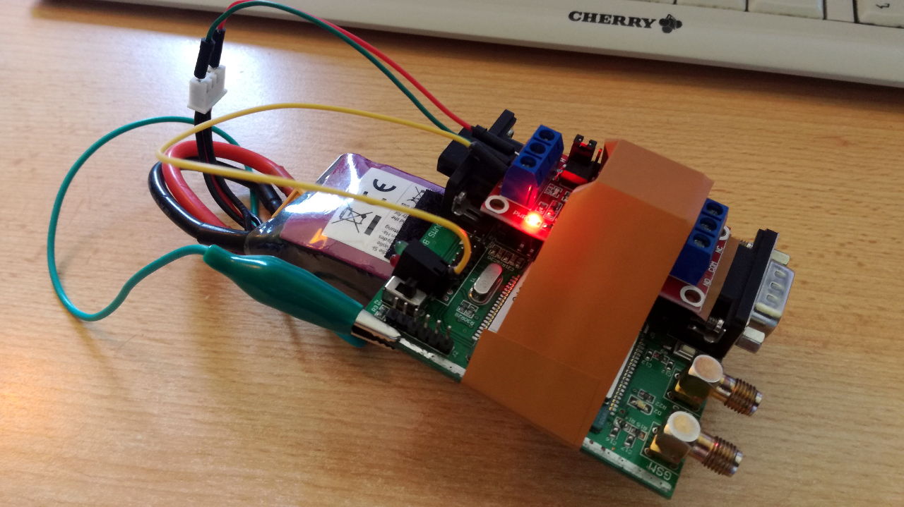
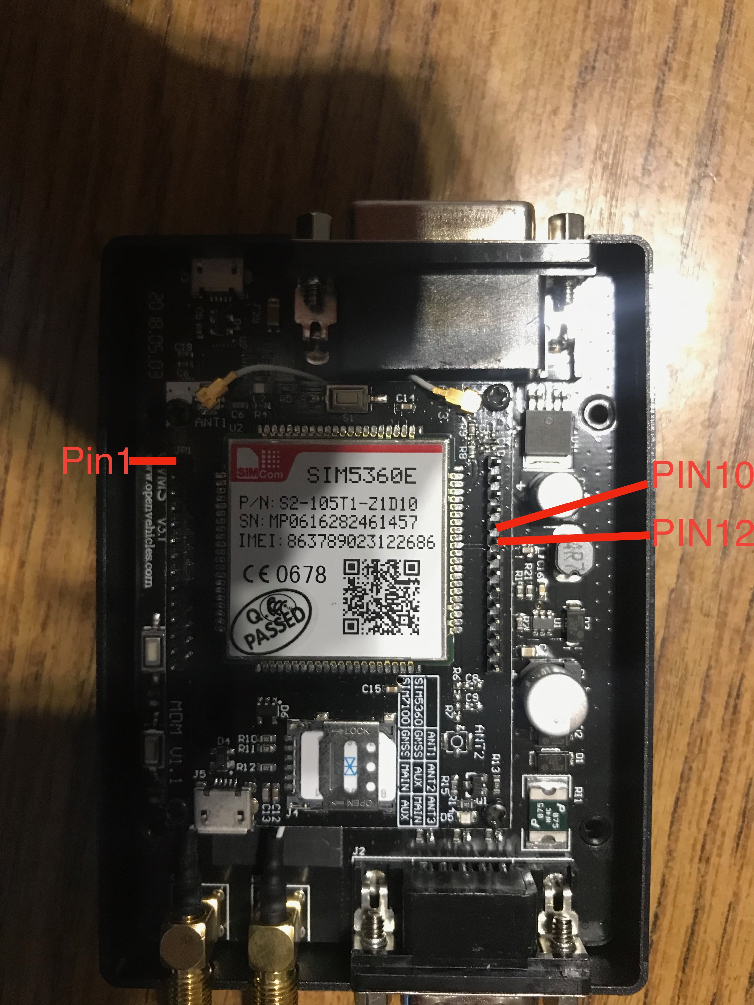
Here are the prototype prototypes. They seem fine to me. Just some minor adjustments and we will go with these. Three in a batch, unsoldered, with pin headers. I’m still waiting for news on the certification; hopefully know within the next few days. Once we know what is going on with that, we can confirm the next production batch and include these in with that (to keep costs as low as possible). Regards, Mark.
On 19 Apr 2019, at 5:08 AM, Michael Balzer <dexter@expeedo.de> wrote:
Mark,
that looks very good. Not sure about general demand, but I think we should have this to enable simple custom hardware I/O extensions.
For the Twizy, I was thinking about adding logic to control the brake light from the module. The Twizy does not activate the brake light on recuperation, as that's normally (untuned) not very strong. But a tuned Twizy allows one pedal driving, so needs this.
Looking at our case I also think one custom extension board should fit on top of the modem.
Regards, Michael
Am 18.04.19 um 02:36 schrieb Mark Webb-Johnson:
It seems the attachments were messed up, so attaching again…
Regards, Mark.
On 17 Apr 2019, at 10:07 PM, Mark Webb-Johnson <mark@webb-johnson.net <mailto:mark@webb-johnson.net>> wrote:
Design layout. Looks good to me, but open to suggestions...
We can make in sets of three PCBs, to keep prices down.
Regards, Mark
On 8 Apr 2019, at 12:05 PM, Mark Webb-Johnson <mark@webb-johnson.net <mailto:mark@webb-johnson.net>> wrote:
A kit of 5 PCBs + SIP edge connectors + mounting hardware, unsoldered, would be about US$15 + shipping. About US$3/board set. With shipping I don’t think this is worth doing with less than 3 or 5 boards per kit.
Would this be useful?
Regards, Mark.
On 7 Apr 2019, at 9:08 PM, Mark Webb-Johnson <mark@webb-johnson.net <mailto:mark@webb-johnson.net>> wrote:
This is the closest we have today:
<image1.jpeg>
That is a bare modem board, with just the sip connectors. The prototype above is a K-line transceiver.
I think it would be trivial, and cheap, to make up what you show. Perhaps just solder ready pads at 0.1” pitch, then the side sip connectors wired to the first row of pads at each edge. Perhaps 5 PCBs in a kit, with sip edge connectors, unsoldered, in a simple plastic bag.
Does that sound like something useful? If so, I can ask the China guys for some idea of pricing. If it is just the unsoldered pcbs + parts, I don’t think it will be expensive.
Regards, Mark
On 7 Apr 2019, at 4:38 PM, Michael Balzer <dexter@expeedo.de <mailto:dexter@expeedo.de>> wrote:
Mark,
do you know of some kind of prototyping board available that fits to our piggy back expansion layout?
Something like this: https://www.robotshop.com/de/de/cytron-arduino-proto-schild.html <https://www.robotshop.com/de/de/cytron-arduino-proto-schild.html>
Regards, Michael
Am 03.04.19 um 06:48 schrieb Mark Webb-Johnson: > > If you have work to do on this DA26 expansion ports, this is pretty cool and well built: > > https://www.aliexpress.com/item/26-Pin-D-SUB-DB26-3-Rows-Serial-Parallel-Por... <https://www.aliexpress.com/item/26-Pin-D-SUB-DB26-3-Rows-Serial-Parallel-Port-Serial-Shellless-Male-And-Female-Connector/32886738786.html?spm=a2g0s.9042311.0.0.20924c4dg34EEU> > > > > > > > > _______________________________________________ > OvmsDev mailing list > OvmsDev@lists.openvehicles.com <mailto:OvmsDev@lists.openvehicles.com> > http://lists.openvehicles.com/mailman/listinfo/ovmsdev <http://lists.openvehicles.com/mailman/listinfo/ovmsdev>
-- Michael Balzer * Helkenberger Weg 9 * D-58256 Ennepetal Fon 02333 / 833 5735 * Handy 0176 / 206 989 26 _______________________________________________ OvmsDev mailing list OvmsDev@lists.openvehicles.com <mailto:OvmsDev@lists.openvehicles.com> http://lists.openvehicles.com/mailman/listinfo/ovmsdev <http://lists.openvehicles.com/mailman/listinfo/ovmsdev>
OvmsDev mailing list OvmsDev@lists.openvehicles.com <mailto:OvmsDev@lists.openvehicles.com> http://lists.openvehicles.com/mailman/listinfo/ovmsdev <http://lists.openvehicles.com/mailman/listinfo/ovmsdev>
_______________________________________________ OvmsDev mailing list OvmsDev@lists.openvehicles.com <mailto:OvmsDev@lists.openvehicles.com> http://lists.openvehicles.com/mailman/listinfo/ovmsdev <http://lists.openvehicles.com/mailman/listinfo/ovmsdev>
_______________________________________________ OvmsDev mailing list OvmsDev@lists.openvehicles.com <mailto:OvmsDev@lists.openvehicles.com> http://lists.openvehicles.com/mailman/listinfo/ovmsdev <http://lists.openvehicles.com/mailman/listinfo/ovmsdev>
_______________________________________________ OvmsDev mailing list OvmsDev@lists.openvehicles.com <mailto:OvmsDev@lists.openvehicles.com> http://lists.openvehicles.com/mailman/listinfo/ovmsdev <http://lists.openvehicles.com/mailman/listinfo/ovmsdev>
-- Michael Balzer * Helkenberger Weg 9 * D-58256 Ennepetal Fon 02333 / 833 5735 * Handy 0176 / 206 989 26 _______________________________________________ OvmsDev mailing list OvmsDev@lists.openvehicles.com http://lists.openvehicles.com/mailman/listinfo/ovmsdev
Some more prototype pictures. There is about 6.5m space between the top of the board and standard case; that is tight, but just about ok for normal components. All looks ok, and we are proceeding like this. Regards, Mark.
On 21 Apr 2019, at 8:57 PM, Mark Webb-Johnson <mark@webb-johnson.net> wrote:
Here are the prototype prototypes. They seem fine to me. Just some minor adjustments and we will go with these. Three in a batch, unsoldered, with pin headers.
I’m still waiting for news on the certification; hopefully know within the next few days. Once we know what is going on with that, we can confirm the next production batch and include these in with that (to keep costs as low as possible).
Regards, Mark.
<IMG_20190421_141816_resized_20190421_022448100.jpeg><IMG_20190421_141807_resized_20190421_022448350.jpeg>
On 19 Apr 2019, at 5:08 AM, Michael Balzer <dexter@expeedo.de <mailto:dexter@expeedo.de>> wrote:
Mark,
that looks very good. Not sure about general demand, but I think we should have this to enable simple custom hardware I/O extensions.
For the Twizy, I was thinking about adding logic to control the brake light from the module. The Twizy does not activate the brake light on recuperation, as that's normally (untuned) not very strong. But a tuned Twizy allows one pedal driving, so needs this.
Looking at our case I also think one custom extension board should fit on top of the modem.
Regards, Michael
Am 18.04.19 um 02:36 schrieb Mark Webb-Johnson:
It seems the attachments were messed up, so attaching again…
Regards, Mark.
On 17 Apr 2019, at 10:07 PM, Mark Webb-Johnson <mark@webb-johnson.net <mailto:mark@webb-johnson.net>> wrote:
Design layout. Looks good to me, but open to suggestions...
We can make in sets of three PCBs, to keep prices down.
Regards, Mark
On 8 Apr 2019, at 12:05 PM, Mark Webb-Johnson <mark@webb-johnson.net <mailto:mark@webb-johnson.net>> wrote:
A kit of 5 PCBs + SIP edge connectors + mounting hardware, unsoldered, would be about US$15 + shipping. About US$3/board set. With shipping I don’t think this is worth doing with less than 3 or 5 boards per kit.
Would this be useful?
Regards, Mark.
On 7 Apr 2019, at 9:08 PM, Mark Webb-Johnson <mark@webb-johnson.net <mailto:mark@webb-johnson.net>> wrote:
This is the closest we have today:
<image1.jpeg>
That is a bare modem board, with just the sip connectors. The prototype above is a K-line transceiver.
I think it would be trivial, and cheap, to make up what you show. Perhaps just solder ready pads at 0.1” pitch, then the side sip connectors wired to the first row of pads at each edge. Perhaps 5 PCBs in a kit, with sip edge connectors, unsoldered, in a simple plastic bag.
Does that sound like something useful? If so, I can ask the China guys for some idea of pricing. If it is just the unsoldered pcbs + parts, I don’t think it will be expensive.
Regards, Mark
On 7 Apr 2019, at 4:38 PM, Michael Balzer <dexter@expeedo.de <mailto:dexter@expeedo.de>> wrote:
> Mark, > > do you know of some kind of prototyping board available that fits to our piggy back expansion layout? > > Something like this: https://www.robotshop.com/de/de/cytron-arduino-proto-schild.html <https://www.robotshop.com/de/de/cytron-arduino-proto-schild.html> > > Regards, > Michael > > > Am 03.04.19 um 06:48 schrieb Mark Webb-Johnson: >> >> If you have work to do on this DA26 expansion ports, this is pretty cool and well built: >> >> https://www.aliexpress.com/item/26-Pin-D-SUB-DB26-3-Rows-Serial-Parallel-Por... <https://www.aliexpress.com/item/26-Pin-D-SUB-DB26-3-Rows-Serial-Parallel-Port-Serial-Shellless-Male-And-Female-Connector/32886738786.html?spm=a2g0s.9042311.0.0.20924c4dg34EEU> >> >> >> >> >> >> >> >> _______________________________________________ >> OvmsDev mailing list >> OvmsDev@lists.openvehicles.com <mailto:OvmsDev@lists.openvehicles.com> >> http://lists.openvehicles.com/mailman/listinfo/ovmsdev <http://lists.openvehicles.com/mailman/listinfo/ovmsdev> > > -- > Michael Balzer * Helkenberger Weg 9 * D-58256 Ennepetal > Fon 02333 / 833 5735 * Handy 0176 / 206 989 26 > _______________________________________________ > OvmsDev mailing list > OvmsDev@lists.openvehicles.com <mailto:OvmsDev@lists.openvehicles.com> > http://lists.openvehicles.com/mailman/listinfo/ovmsdev <http://lists.openvehicles.com/mailman/listinfo/ovmsdev> _______________________________________________ OvmsDev mailing list OvmsDev@lists.openvehicles.com <mailto:OvmsDev@lists.openvehicles.com> http://lists.openvehicles.com/mailman/listinfo/ovmsdev <http://lists.openvehicles.com/mailman/listinfo/ovmsdev>
_______________________________________________ OvmsDev mailing list OvmsDev@lists.openvehicles.com <mailto:OvmsDev@lists.openvehicles.com> http://lists.openvehicles.com/mailman/listinfo/ovmsdev <http://lists.openvehicles.com/mailman/listinfo/ovmsdev>
_______________________________________________ OvmsDev mailing list OvmsDev@lists.openvehicles.com <mailto:OvmsDev@lists.openvehicles.com> http://lists.openvehicles.com/mailman/listinfo/ovmsdev <http://lists.openvehicles.com/mailman/listinfo/ovmsdev>
_______________________________________________ OvmsDev mailing list OvmsDev@lists.openvehicles.com <mailto:OvmsDev@lists.openvehicles.com> http://lists.openvehicles.com/mailman/listinfo/ovmsdev <http://lists.openvehicles.com/mailman/listinfo/ovmsdev>
-- Michael Balzer * Helkenberger Weg 9 * D-58256 Ennepetal Fon 02333 / 833 5735 * Handy 0176 / 206 989 26 _______________________________________________ OvmsDev mailing list OvmsDev@lists.openvehicles.com <mailto:OvmsDev@lists.openvehicles.com> http://lists.openvehicles.com/mailman/listinfo/ovmsdev
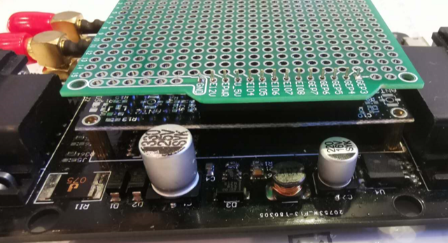
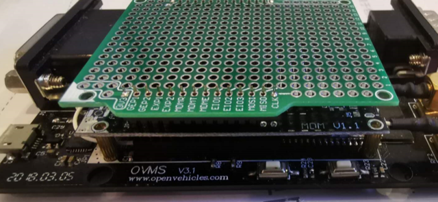
On 2019-04-22 20:10, Mark Webb-Johnson wrote:
Some more prototype pictures. There is about 6.5m space between the top of the board and standard case; that is tight, but just about ok for normal components.
That looks really good to me. There are a pair of 1x14 sockets tacked onto it? Will there be standoffs too? Craig
Current plan is that each set will contain: 3x PCBs 12x screws 12x support pillars 6x 14 pins female single header 6x 14 pins male single header In a simple plastic bag, with nothing soldered. It is ready to go ahead now. Only delay is certification (as I want to do this in combination with the new batch order, to keep costs down). Regards, Mark.
On 23 Apr 2019, at 2:25 PM, Craig Leres <leres@xse.com> wrote:
On 2019-04-22 20:10, Mark Webb-Johnson wrote:
Some more prototype pictures. There is about 6.5m space between the top of the board and standard case; that is tight, but just about ok for normal components.
That looks really good to me. There are a pair of 1x14 sockets tacked onto it? Will there be standoffs too?
Craig
participants (6)
-
 Brian Greenberg
 -
 Craig Leres
 -
 Julien “JaXX” Banchet
 -
 Mark Webb-Johnson
 -
 Michael Balzer
 -
 Tamás Kovács