
I would like to devise something to incentivise / reward people working on this project. Something beyond the personal satisfaction, and giving back to the community. What I'm thinking is to donate hardware modules to people working on new vehicle support. It would work something like this: Someone steps forward to take on support for a particular vehicle. That developer buys the hardware module, and accessories, as normal. The vehicle_xxx.c file is written, tested, and gets to a stage where it meets the milestones for that vehicle (the core functionality requirements). Open Vehicles either re-imburses the module purchase price, or sends a second module to the developer concerned (option chosen by the developer). In particular, I'd really like to incentivise work on the Leaf and iMiev modules. What about for past contributors? What about for people working on the Apps, or other parts of the system? What do people think? Would this be a good idea, or no use? Regards, Mark. P.S. What I would really like to do is get the OVMS CAN-USB adaptor working, and then give those out in large quantities. The more people decoding vehicle CAN communications, the more cars become open vehicles. But, to do that I need some one / people to step forward and help with this. The China manufacturer is standing by and asking me for the circuit diagram, but I've got too much on my plate at the moment to take on the CAN-USB hardware and firmware as well. Using a PIC32 microprocessor (with built-in USB support), and MCP2551 CAN controller, we can do this for a materials cost perhaps around US$30 (vs US$150 retail for the cheapest commercial units). I'll send out a separate 'appeal' for this, and see if anyone will step forward to help.

Hi, i think this is a good idea. Could help to multiply the developers. Now the "old" developers can do some propaganda with this in mind. Bye Michael Am 29.08.2013 um 03:25 schrieb Mark Webb-Johnson <mark@webb-johnson.net>:
I would like to devise something to incentivise / reward people working on this project. Something beyond the personal satisfaction, and giving back to the community.
What I'm thinking is to donate hardware modules to people working on new vehicle support. It would work something like this:
Someone steps forward to take on support for a particular vehicle. That developer buys the hardware module, and accessories, as normal. The vehicle_xxx.c file is written, tested, and gets to a stage where it meets the milestones for that vehicle (the core functionality requirements). Open Vehicles either re-imburses the module purchase price, or sends a second module to the developer concerned (option chosen by the developer).
In particular, I'd really like to incentivise work on the Leaf and iMiev modules.
What about for past contributors? What about for people working on the Apps, or other parts of the system?
What do people think? Would this be a good idea, or no use?

Hi Mark, I would be interested in developing USB firmware for the PIC32 that meets your CAN-USB adaptor goals. I have experience writing USB firmware for multiple USB Device classes (not just plain serial), including working with the Microchip USB Stack. I purchased the OVMS v2 with the goal of learning more about CAN signaling on my Roadster. I haven't actually used the device because I'm not primarily interested in getting a SIM card and paying for network access. I wanted to support your efforts at making a hardware platform, and I figured that I could just write my own custom hardware for recording and analyzing CAN messages. Unfortunately, as you're probably aware, the OVMS v2 is not immediately useful for my project. Also, I can imagine that you know what it's like to have more ideas than time. The only question is how to incentivize the effort. It would be ideal if you could pay for the PIC32 USB firmware development, but I can see how that might not be within your budget. Another alternative is to just send me the new platform, and I might be able to make some progress. On that note, I would be willing to review the hardware designs before you make prototypes, just to see if I think there is anything missing in the hardware circuitry. Since I have experience designing USB platforms based on the PIC and other embedded processors, it might be worth having a second set of eyes look over the design. Also, with my combined hardware and firmware design experience, I think I have a particularly good sense of what makes a good hardware platform for particular firmware projects. Let me know what you think. To reiterate, I'm willing to look at the hardware design without charging anything. The reward for me will be enough to know that a new platform that I like will be made. As for firmware design, I'm hoping that some sort of compensation can be arranged, because that is much more effort. However, I think we may be able to work something out that is mutually beneficial. Brian Willoughby Sound Consulting p.s. Regarding my existing OVMS v2, I would actually enjoy having the SIM card working for when I charge on the road, but it's just not a priority. On Aug 28, 2013, at 18:25, Mark Webb-Johnson wrote:
P.S. What I would really like to do is get the OVMS CAN-USB adaptor working, and then give those out in large quantities. The more people decoding vehicle CAN communications, the more cars become open vehicles. But, to do that I need some one / people to step forward and help with this. The China manufacturer is standing by and asking me for the circuit diagram, but I've got too much on my plate at the moment to take on the CAN-USB hardware and firmware as well. Using a PIC32 microprocessor (with built-in USB support), and MCP2551 CAN controller, we can do this for a materials cost perhaps around US$30 (vs US$150 retail for the cheapest commercial units). I'll send out a separate 'appeal' for this, and see if anyone will step forward to help.
Brian, OK, let's concentrate on hardware first. So far, as far as I've got is prototyping something using: UBW32 (https://www.sparkfun.com/products/9713) PIC32MX795 development board. MCP2551 CAN controller (http://www.microchip.com/wwwproducts/Devices.aspx?dDocName=en010405). FT232RL based converter (https://www.sparkfun.com/products/718). The FT232RL was just wired to the first async port of the PIC32, and the MCP2551 connected straight to the PIC32 as well using the normal CAN controller ports. That was the prototype. For production, I don't think we need the FT232RL at all. We should be able to use the PIC32 USB and have it present as a serial port to the host (windows, linux, osx, Android?). I have played around some with the PIC USB library (I built a little HID keyboard media player for my car - https://github.com/markwj/hidmedia). But, I haven't spent much time with the PIC32 USB framework as a serial port and have no idea how the driver support works. Components wise, I reckon we need: USB connector, and support components 5V-3.3V power regulator PIC32MX795 and support components MCP2551, and support components DB9 connector, either "standard" CAN-on-DB9 or OVMS-on-DB9 pinout Switch for program/run mode ICSP pins Case I suggest to power from the USB port, not from the vehicle side 12V. The MCP2551 (and CAN bus) is 5V, but I think can be powered directly from the USB port. The PIC32MX795 is 3.3v. But, both are tolerant and seem to be able to be inter-connected without any issues (the MCP2551 trigger level is <3.3V, and the PIC32MX795 is 5V tolerant on the CAN RX pin). I've used these products: http://www.can232.com and they have a simple serial API that I am already using with my CAN-RE-TOOL: http://www.can232.com/docs/canusb_manual.pdf I've discussed with the factory in China, and it seems fairly simple. They have done similar projects before, using the case shown below. Plenty of room and we can either use a USB type B socket, or type A plug on the end of a soldered-in cable. The PIC32 is definitely overkill, but given the price of the chip, I don't think it is much of an issue - it will give us plenty of room to do whatever we need. Regards, Mark. On 1 Sep, 2013, at 6:41 AM, HONDA S-2000 <s2000@sounds.wa.com> wrote:
Hi Mark,
I would be interested in developing USB firmware for the PIC32 that meets your CAN-USB adaptor goals. I have experience writing USB firmware for multiple USB Device classes (not just plain serial), including working with the Microchip USB Stack.
I purchased the OVMS v2 with the goal of learning more about CAN signaling on my Roadster. I haven't actually used the device because I'm not primarily interested in getting a SIM card and paying for network access. I wanted to support your efforts at making a hardware platform, and I figured that I could just write my own custom hardware for recording and analyzing CAN messages. Unfortunately, as you're probably aware, the OVMS v2 is not immediately useful for my project. Also, I can imagine that you know what it's like to have more ideas than time.
The only question is how to incentivize the effort. It would be ideal if you could pay for the PIC32 USB firmware development, but I can see how that might not be within your budget. Another alternative is to just send me the new platform, and I might be able to make some progress. On that note, I would be willing to review the hardware designs before you make prototypes, just to see if I think there is anything missing in the hardware circuitry. Since I have experience designing USB platforms based on the PIC and other embedded processors, it might be worth having a second set of eyes look over the design. Also, with my combined hardware and firmware design experience, I think I have a particularly good sense of what makes a good hardware platform for particular firmware projects.
Let me know what you think.
To reiterate, I'm willing to look at the hardware design without charging anything. The reward for me will be enough to know that a new platform that I like will be made. As for firmware design, I'm hoping that some sort of compensation can be arranged, because that is much more effort. However, I think we may be able to work something out that is mutually beneficial.
Brian Willoughby Sound Consulting
p.s. Regarding my existing OVMS v2, I would actually enjoy having the SIM card working for when I charge on the road, but it's just not a priority.
On Aug 28, 2013, at 18:25, Mark Webb-Johnson wrote:
P.S. What I would really like to do is get the OVMS CAN-USB adaptor working, and then give those out in large quantities. The more people decoding vehicle CAN communications, the more cars become open vehicles. But, to do that I need some one / people to step forward and help with this. The China manufacturer is standing by and asking me for the circuit diagram, but I've got too much on my plate at the moment to take on the CAN-USB hardware and firmware as well. Using a PIC32 microprocessor (with built-in USB support), and MCP2551 CAN controller, we can do this for a materials cost perhaps around US$30 (vs US$150 retail for the cheapest commercial units). I'll send out a separate 'appeal' for this, and see if anyone will step forward to help.
_______________________________________________ OvmsDev mailing list OvmsDev@lists.teslaclub.hk http://lists.teslaclub.hk/mailman/listinfo/ovmsdev
This all sounds good. I agree with eliminating the FT232RL. The PIC32MX795 can maintain the serial USB feature or use a custom class USB for easier control protocol. Serial can be more cumbersome and error prone because all bytes are equivalent, and you have to rely upon parsing to identify individual commands and data. Custom class USB allows you to use the features of USB that separate commands from data and make the size of the transfers more definitive. OSX allows standard applications to access custom USB devices without a custom driver. Linux hopefully allows the same by using libusb, although I have no experience there. Windows seems to require a driver for everything, but I don't know the actual limitations. You'll probably need a USB VID and PID (Vendor ID and Product ID). If you don't already have one then Microchip might make a PID available once you fill out their request paperwork. Any reason to avoid the 12V vehicle power? I suppose that simplifies the hardware. This USB-CAN device is not useful for much except logging unless it is plugged in to a USB host. On that note, perhaps it's worth designing the PCB for a 12V power option, but perhaps not populate the parts, so that someone who wants to do unattended logging could power the board without a laptop sitting in the car. You may not need a switch for program versus run mode - at least I've gotten away without one, but it does make it easier for field firmware upgrades, I suppose, if there is a switch. With the right circuit, it might be possible to leave the switch off the PCB for the commercial product, assuming that saves money and firmware upgrades are not frequent. I'll study the CAN232 manual and Sparkfun UBW32 schematic... Brian Willoughby Sound Consulting On Sep 1, 2013, at 18:56, Mark Webb-Johnson wrote:
Brian,
OK, let's concentrate on hardware first.
So far, as far as I've got is prototyping something using:
UBW32 (https://www.sparkfun.com/products/9713) PIC32MX795 development board.
MCP2551 CAN controller (http://www.microchip.com/wwwproducts/ Devices.aspx?dDocName=en010405).
FT232RL based converter (https://www.sparkfun.com/products/718).
The FT232RL was just wired to the first async port of the PIC32, and the MCP2551 connected straight to the PIC32 as well using the normal CAN controller ports.
That was the prototype. For production, I don't think we need the FT232RL at all. We should be able to use the PIC32 USB and have it present as a serial port to the host (windows, linux, osx, Android?). I have played around some with the PIC USB library (I built a little HID keyboard media player for my car - https:// github.com/markwj/hidmedia). But, I haven't spent much time with the PIC32 USB framework as a serial port and have no idea how the driver support works.
Components wise, I reckon we need:
USB connector, and support components 5V-3.3V power regulator PIC32MX795 and support components MCP2551, and support components DB9 connector, either "standard" CAN-on-DB9 or OVMS-on-DB9 pinout Switch for program/run mode ICSP pins Case
I suggest to power from the USB port, not from the vehicle side 12V. The MCP2551 (and CAN bus) is 5V, but I think can be powered directly from the USB port. The PIC32MX795 is 3.3v. But, both are tolerant and seem to be able to be inter-connected without any issues (the MCP2551 trigger level is <3.3V, and the PIC32MX795 is 5V tolerant on the CAN RX pin).
I've used these products:
and they have a simple serial API that I am already using with my CAN-RE-TOOL:
http://www.can232.com/docs/canusb_manual.pdf
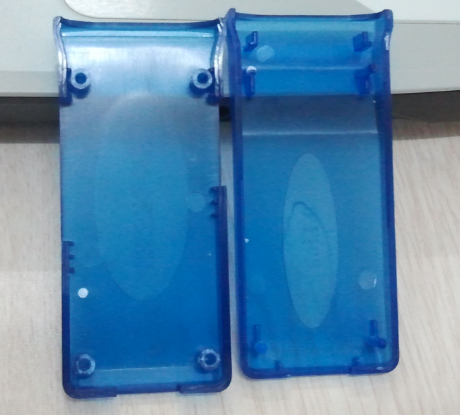
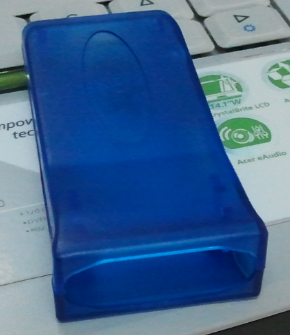
I've discussed with the factory in China, and it seems fairly simple. They have done similar projects before, using the case shown below. Plenty of room and we can either use a USB type B socket, or type A plug on the end of a soldered-in cable. The PIC32 is definitely overkill, but given the price of the chip, I don't think it is much of an issue - it will give us plenty of room to do whatever we need.
Regards, Mark.
Custom class USB allows you to use the features of USB that separate commands from data and make the size of the transfers more definitive.
I really would prefer driver-less, if at all possible. A simple serial control VCP. With a powerful-enough processor (and the difference between an 8bit PIC and a 32bit PIC is US$2), we have a lot of opportunity to offload work to the USB-CAN adaptor itself (for example high-level filters), and I don't think we will be baud-rate limited. Perhaps if there is an advantage with custom class USB, we can offer both interfaces?
You'll probably need a USB VID and PID (Vendor ID and Product ID). If you don't already have one then Microchip might make a PID available once you fill out their request paperwork.
Sending it in now - it is worth a try.
Any reason to avoid the 12V vehicle power? I suppose that simplifies the hardware.
Yeah, just to keep it simple (and cheap). We would still need 5V->3.3V. Unattended logging would be cool, but only 128KB RAM in the device, and adding an SD-CARD would complicate things.
You may not need a switch for program versus run mode - at least I've gotten away without one, but it does make it easier for field firmware upgrades, I suppose, if there is a switch.
Being able to re-flash the device from USB is definitely a requirement. We don't want people to have to go the PICKIT / ICSP route. I'll try to rough up a schematic, to see how many components this can be brought down to. For China manufacturers, saving even 1 component brings the cost of both materials and assembly down. I remember working with the factory to remove 1 single chip costing US$1.10 down to a bunch of passive components costing US$0.10 - resulting price difference was US$3 (I think they really didn't want to use that chip, not just for the cost but also for the hassle of obtaining it). I really want to get this to DB9 - MCP2551 - PIC32 - USB, with minimal external components. Regards, Mark On 3 Sep, 2013, at 6:48 AM, HONDA S-2000 <s2000@sounds.wa.com> wrote:
This all sounds good.
I agree with eliminating the FT232RL. The PIC32MX795 can maintain the serial USB feature or use a custom class USB for easier control protocol. Serial can be more cumbersome and error prone because all bytes are equivalent, and you have to rely upon parsing to identify individual commands and data. Custom class USB allows you to use the features of USB that separate commands from data and make the size of the transfers more definitive.
OSX allows standard applications to access custom USB devices without a custom driver.
Linux hopefully allows the same by using libusb, although I have no experience there.
Windows seems to require a driver for everything, but I don't know the actual limitations.
You'll probably need a USB VID and PID (Vendor ID and Product ID). If you don't already have one then Microchip might make a PID available once you fill out their request paperwork.
Any reason to avoid the 12V vehicle power? I suppose that simplifies the hardware. This USB-CAN device is not useful for much except logging unless it is plugged in to a USB host. On that note, perhaps it's worth designing the PCB for a 12V power option, but perhaps not populate the parts, so that someone who wants to do unattended logging could power the board without a laptop sitting in the car.
You may not need a switch for program versus run mode - at least I've gotten away without one, but it does make it easier for field firmware upgrades, I suppose, if there is a switch. With the right circuit, it might be possible to leave the switch off the PCB for the commercial product, assuming that saves money and firmware upgrades are not frequent.
I'll study the CAN232 manual and Sparkfun UBW32 schematic...
Brian Willoughby Sound Consulting
On Sep 1, 2013, at 18:56, Mark Webb-Johnson wrote:
Brian,
OK, let's concentrate on hardware first.
So far, as far as I've got is prototyping something using:
UBW32 (https://www.sparkfun.com/products/9713) PIC32MX795 development board.
MCP2551 CAN controller (http://www.microchip.com/wwwproducts/Devices.aspx?dDocName=en010405).
FT232RL based converter (https://www.sparkfun.com/products/718).
The FT232RL was just wired to the first async port of the PIC32, and the MCP2551 connected straight to the PIC32 as well using the normal CAN controller ports.
That was the prototype. For production, I don't think we need the FT232RL at all. We should be able to use the PIC32 USB and have it present as a serial port to the host (windows, linux, osx, Android?). I have played around some with the PIC USB library (I built a little HID keyboard media player for my car - https://github.com/markwj/hidmedia). But, I haven't spent much time with the PIC32 USB framework as a serial port and have no idea how the driver support works.
Components wise, I reckon we need:
USB connector, and support components 5V-3.3V power regulator PIC32MX795 and support components MCP2551, and support components DB9 connector, either "standard" CAN-on-DB9 or OVMS-on-DB9 pinout Switch for program/run mode ICSP pins Case
I suggest to power from the USB port, not from the vehicle side 12V. The MCP2551 (and CAN bus) is 5V, but I think can be powered directly from the USB port. The PIC32MX795 is 3.3v. But, both are tolerant and seem to be able to be inter-connected without any issues (the MCP2551 trigger level is <3.3V, and the PIC32MX795 is 5V tolerant on the CAN RX pin).
I've used these products:
and they have a simple serial API that I am already using with my CAN-RE-TOOL:
http://www.can232.com/docs/canusb_manual.pdf
I've discussed with the factory in China, and it seems fairly simple. They have done similar projects before, using the case shown below. Plenty of room and we can either use a USB type B socket, or type A plug on the end of a soldered-in cable. The PIC32 is definitely overkill, but given the price of the chip, I don't think it is much of an issue - it will give us plenty of room to do whatever we need.
Regards, Mark.
_______________________________________________ OvmsDev mailing list OvmsDev@lists.teslaclub.hk http://lists.teslaclub.hk/mailman/listinfo/ovmsdev
On Sep 2, 2013, at 18:28, Mark Webb-Johnson wrote:
Custom class USB allows you to use the features of USB that separate commands from data and make the size of the transfers more definitive.
I really would prefer driver-less, if at all possible. A simple serial control VCP. With a powerful-enough processor (and the difference between an 8bit PIC and a 32bit PIC is US$2), we have a lot of opportunity to offload work to the USB-CAN adaptor itself (for example high-level filters), and I don't think we will be baud- rate limited. Perhaps if there is an advantage with custom class USB, we can offer both interfaces?
Offloading is possible no matter what class the device is. Baud-rate is not really the issue. The one thing I've noticed is that the serial protocol can get really messy, and that's basically about separating commands from data, or otherwise detecting the boundaries of packets of information. That's what the USB protocol is good for, and it can really simplify the protocol. Also, I've seen some designs where the device gets stuck in data mode, requiring the device to be restarted to get back into command mode, and that wouldn't be an issue with a custom class. Multiple interfaces would be a great way to gain the advantages of both approaches, time permitting.
Any reason to avoid the 12V vehicle power? I suppose that simplifies the hardware.
Yeah, just to keep it simple (and cheap). We would still need 5V-
3.3V. Unattended logging would be cool, but only 128KB RAM in the device, and adding an SD-CARD would complicate things. 128KB can be enough if the logging is both specific to a certain subset of messages, and compressed or compacted. In any event, I imagine that a simply USB charger could keep the board powered for unattended logging.
I'll try to rough up a schematic, to see how many components this can be brought down to. For China manufacturers, saving even 1 component brings the cost of both materials and assembly down. I remember working with the factory to remove 1 single chip costing US $1.10 down to a bunch of passive components costing US$0.10 - resulting price difference was US$3 (I think they really didn't want to use that chip, not just for the cost but also for the hassle of obtaining it). So, passives do not count as a whole component, not compared to a chip?
I really want to get this to DB9 - MCP2551 - PIC32 - USB, with minimal external components.
I don't see why that wouldn't be possible. A lot easier than the OVMS, which has lots of cool features and subboards. Brian
Any reason to avoid the 12V vehicle power? I suppose that simplifies the hardware.
Yeah, just to keep it simple (and cheap). We would still need 5V->3.3V. Unattended logging would be cool, but only 128KB RAM in the device, and adding an SD-CARD would complicate things. 128KB can be enough if the logging is both specific to a certain subset of messages, and compressed or compacted. In any event, I imagine that a simply USB charger could keep the board powered for unattended logging.
Neat idea. That can keep the cost down, and keep things simple. Just a little cigarette lighter USB charger, or perhaps one of those external batteries, should do the job.
I'll try to rough up a schematic, to see how many components this can be brought down to. For China manufacturers, saving even 1 component brings the cost of both materials and assembly down. I remember working with the factory to remove 1 single chip costing US$1.10 down to a bunch of passive components costing US$0.10 - resulting price difference was US$3 (I think they really didn't want to use that chip, not just for the cost but also for the hassle of obtaining it). So, passives do not count as a whole component, not compared to a chip?
Supposedly not. Or, at least they don't concern themselves with them. I suspect that the factories have rolls of hundreds of thousands of these components, ready to go. Sometimes if I specify a 2.3k resistor, for example, they will come back and ask to substitute with 2.2k - but that happens surprisingly rarely. Their biggest concern seems to be the ICs - or maybe they are just concentrating on things that cost more than a buck. Years ago, I remember we were hand-building these little opto-isolation circuit boards for US$15 a piece. We needed a batch of about 200, and the factory came back with a few minor changes and a minimum order quantity of 2,000 at a per-unit cost of US$1. So, we got 2,000 of them for less than the price of our hand-built 200. It is amazing how cheaply things can be in quantity from China. And, for all people denigrate the Chinese factories, quality can be amazing if you find the right people. OVMS v1 (hand built and soldered) was a pain in the arse. OVMS v2 (automated, on a single board) has had <0.5% failure rate. For modules like OVMS (and presumably this little CAN-USB), the magic quantity seems to be about 100 nowadays. At that quantity, we can get machine-soldered boards - and the difference between hand and machine soldered is like night and day for quality. At that quantity, we can also get customised metal enclosures (although I suspect the quantity would be higher for a customised plastic enclosure). Regards, Mark. On 3 Sep, 2013, at 11:35 AM, HONDA S-2000 <s2000@sounds.wa.com> wrote:
On Sep 2, 2013, at 18:28, Mark Webb-Johnson wrote:
Custom class USB allows you to use the features of USB that separate commands from data and make the size of the transfers more definitive.
I really would prefer driver-less, if at all possible. A simple serial control VCP. With a powerful-enough processor (and the difference between an 8bit PIC and a 32bit PIC is US$2), we have a lot of opportunity to offload work to the USB-CAN adaptor itself (for example high-level filters), and I don't think we will be baud-rate limited. Perhaps if there is an advantage with custom class USB, we can offer both interfaces?
Offloading is possible no matter what class the device is. Baud-rate is not really the issue. The one thing I've noticed is that the serial protocol can get really messy, and that's basically about separating commands from data, or otherwise detecting the boundaries of packets of information. That's what the USB protocol is good for, and it can really simplify the protocol. Also, I've seen some designs where the device gets stuck in data mode, requiring the device to be restarted to get back into command mode, and that wouldn't be an issue with a custom class.
Multiple interfaces would be a great way to gain the advantages of both approaches, time permitting.
Any reason to avoid the 12V vehicle power? I suppose that simplifies the hardware.
Yeah, just to keep it simple (and cheap). We would still need 5V->3.3V. Unattended logging would be cool, but only 128KB RAM in the device, and adding an SD-CARD would complicate things. 128KB can be enough if the logging is both specific to a certain subset of messages, and compressed or compacted. In any event, I imagine that a simply USB charger could keep the board powered for unattended logging.
I'll try to rough up a schematic, to see how many components this can be brought down to. For China manufacturers, saving even 1 component brings the cost of both materials and assembly down. I remember working with the factory to remove 1 single chip costing US$1.10 down to a bunch of passive components costing US$0.10 - resulting price difference was US$3 (I think they really didn't want to use that chip, not just for the cost but also for the hassle of obtaining it). So, passives do not count as a whole component, not compared to a chip?
I really want to get this to DB9 - MCP2551 - PIC32 - USB, with minimal external components.
I don't see why that wouldn't be possible. A lot easier than the OVMS, which has lots of cool features and subboards.
Brian
_______________________________________________ OvmsDev mailing list OvmsDev@lists.teslaclub.hk http://lists.teslaclub.hk/mailman/listinfo/ovmsdev

Here are my considerations: - the final device will obviously not be an mbed expansion board, but will be a single board with just the mcu. Starting with the mbed is good because all the hardware is already laid out well, especially the ethernet chipset (I was not confident about messing around with it). Also, buying one mbed gives you access to the online compiler and all the libraries, just see it as a "license" and a "donation" to support the project. Then you can move to the lpcxpresso for the next prototypes, and for the final version you just make your own pcb. These boards are very handy to have around anyway. - the ARM core runs at 96mhz, postscaled from the 12mhz crystal - I'm not 100% sure about it, but from what I recall it is possible to load code from an external source on the ARM device, so virtually no limits there. And while it's true that 32 bit code will take up more space, it's also true that you should be able to optimize it better having a bigger instruction set. Finally, while the PIC is in the higher range of microchip's portfolio, the ARM is in the middle-low range of the NXP portfolio, so it may be upgradable now or in the future. - it's been a while since I last looked up C compilers for PICs, but there should be some gcc compiler available. Project pinguino comes to mind: http://pinguino.cc/ they claim that they have a gcc toolchain for PIC32. I'm pretty sure that mbed have a gcc toolchain too. - I just found out about another new project, the Canbus triple: http://www.canb.us/ apart from having an awesome domain name, they made that cool device for a price point that is just 15$ above your target. Maybe you can contact them to arrange a collaboration. Regards Cristiano 2013/9/3 Mark Webb-Johnson <mark@webb-johnson.net>:
Any reason to avoid the 12V vehicle power? I suppose that simplifies the hardware.
Yeah, just to keep it simple (and cheap). We would still need 5V->3.3V. Unattended logging would be cool, but only 128KB RAM in the device, and adding an SD-CARD would complicate things. 128KB can be enough if the logging is both specific to a certain subset of messages, and compressed or compacted. In any event, I imagine that a simply USB charger could keep the board powered for unattended logging.
Neat idea. That can keep the cost down, and keep things simple. Just a little cigarette lighter USB charger, or perhaps one of those external batteries, should do the job.
I'll try to rough up a schematic, to see how many components this can be brought down to. For China manufacturers, saving even 1 component brings the cost of both materials and assembly down. I remember working with the factory to remove 1 single chip costing US$1.10 down to a bunch of passive components costing US$0.10 - resulting price difference was US$3 (I think they really didn't want to use that chip, not just for the cost but also for the hassle of obtaining it). So, passives do not count as a whole component, not compared to a chip?
Supposedly not. Or, at least they don't concern themselves with them. I suspect that the factories have rolls of hundreds of thousands of these components, ready to go. Sometimes if I specify a 2.3k resistor, for example, they will come back and ask to substitute with 2.2k - but that happens surprisingly rarely. Their biggest concern seems to be the ICs - or maybe they are just concentrating on things that cost more than a buck.
Years ago, I remember we were hand-building these little opto-isolation circuit boards for US$15 a piece. We needed a batch of about 200, and the factory came back with a few minor changes and a minimum order quantity of 2,000 at a per-unit cost of US$1. So, we got 2,000 of them for less than the price of our hand-built 200. It is amazing how cheaply things can be in quantity from China. And, for all people denigrate the Chinese factories, quality can be amazing if you find the right people. OVMS v1 (hand built and soldered) was a pain in the arse. OVMS v2 (automated, on a single board) has had <0.5% failure rate.
For modules like OVMS (and presumably this little CAN-USB), the magic quantity seems to be about 100 nowadays. At that quantity, we can get machine-soldered boards - and the difference between hand and machine soldered is like night and day for quality. At that quantity, we can also get customised metal enclosures (although I suspect the quantity would be higher for a customised plastic enclosure).
Regards, Mark.
On 3 Sep, 2013, at 11:35 AM, HONDA S-2000 <s2000@sounds.wa.com> wrote:
On Sep 2, 2013, at 18:28, Mark Webb-Johnson wrote:
Custom class USB allows you to use the features of USB that separate commands from data and make the size of the transfers more definitive.
I really would prefer driver-less, if at all possible. A simple serial control VCP. With a powerful-enough processor (and the difference between an 8bit PIC and a 32bit PIC is US$2), we have a lot of opportunity to offload work to the USB-CAN adaptor itself (for example high-level filters), and I don't think we will be baud-rate limited. Perhaps if there is an advantage with custom class USB, we can offer both interfaces?
Offloading is possible no matter what class the device is. Baud-rate is not really the issue. The one thing I've noticed is that the serial protocol can get really messy, and that's basically about separating commands from data, or otherwise detecting the boundaries of packets of information. That's what the USB protocol is good for, and it can really simplify the protocol. Also, I've seen some designs where the device gets stuck in data mode, requiring the device to be restarted to get back into command mode, and that wouldn't be an issue with a custom class.
Multiple interfaces would be a great way to gain the advantages of both approaches, time permitting.
Any reason to avoid the 12V vehicle power? I suppose that simplifies the hardware.
Yeah, just to keep it simple (and cheap). We would still need 5V->3.3V. Unattended logging would be cool, but only 128KB RAM in the device, and adding an SD-CARD would complicate things. 128KB can be enough if the logging is both specific to a certain subset of messages, and compressed or compacted. In any event, I imagine that a simply USB charger could keep the board powered for unattended logging.
I'll try to rough up a schematic, to see how many components this can be brought down to. For China manufacturers, saving even 1 component brings the cost of both materials and assembly down. I remember working with the factory to remove 1 single chip costing US$1.10 down to a bunch of passive components costing US$0.10 - resulting price difference was US$3 (I think they really didn't want to use that chip, not just for the cost but also for the hassle of obtaining it). So, passives do not count as a whole component, not compared to a chip?
I really want to get this to DB9 - MCP2551 - PIC32 - USB, with minimal external components.
I don't see why that wouldn't be possible. A lot easier than the OVMS, which has lots of cool features and subboards.
Brian
_______________________________________________ OvmsDev mailing list OvmsDev@lists.teslaclub.hk http://lists.teslaclub.hk/mailman/listinfo/ovmsdev
_______________________________________________ OvmsDev mailing list OvmsDev@lists.teslaclub.hk http://lists.teslaclub.hk/mailman/listinfo/ovmsdev
The canb.us system looks cool. But, short on details. I'll contact them to see if they have more detail on the circuit design.
On 3 Sep, 2013, at 8:19 pm, Mastro Gippo <gipmad@gmail.com> wrote:
Here are my considerations: - the final device will obviously not be an mbed expansion board, but will be a single board with just the mcu. Starting with the mbed is good because all the hardware is already laid out well, especially the ethernet chipset (I was not confident about messing around with it). Also, buying one mbed gives you access to the online compiler and all the libraries, just see it as a "license" and a "donation" to support the project. Then you can move to the lpcxpresso for the next prototypes, and for the final version you just make your own pcb. These boards are very handy to have around anyway. - the ARM core runs at 96mhz, postscaled from the 12mhz crystal - I'm not 100% sure about it, but from what I recall it is possible to load code from an external source on the ARM device, so virtually no limits there. And while it's true that 32 bit code will take up more space, it's also true that you should be able to optimize it better having a bigger instruction set. Finally, while the PIC is in the higher range of microchip's portfolio, the ARM is in the middle-low range of the NXP portfolio, so it may be upgradable now or in the future. - it's been a while since I last looked up C compilers for PICs, but there should be some gcc compiler available. Project pinguino comes to mind: http://pinguino.cc/ they claim that they have a gcc toolchain for PIC32. I'm pretty sure that mbed have a gcc toolchain too. - I just found out about another new project, the Canbus triple: http://www.canb.us/ apart from having an awesome domain name, they made that cool device for a price point that is just 15$ above your target. Maybe you can contact them to arrange a collaboration. Regards Cristiano
2013/9/3 Mark Webb-Johnson <mark@webb-johnson.net>:
Any reason to avoid the 12V vehicle power? I suppose that simplifies the hardware.
Yeah, just to keep it simple (and cheap). We would still need 5V->3.3V. Unattended logging would be cool, but only 128KB RAM in the device, and adding an SD-CARD would complicate things. 128KB can be enough if the logging is both specific to a certain subset of messages, and compressed or compacted. In any event, I imagine that a simply USB charger could keep the board powered for unattended logging.
Neat idea. That can keep the cost down, and keep things simple. Just a little cigarette lighter USB charger, or perhaps one of those external batteries, should do the job.
I'll try to rough up a schematic, to see how many components this can be brought down to. For China manufacturers, saving even 1 component brings the cost of both materials and assembly down. I remember working with the factory to remove 1 single chip costing US$1.10 down to a bunch of passive components costing US$0.10 - resulting price difference was US$3 (I think they really didn't want to use that chip, not just for the cost but also for the hassle of obtaining it). So, passives do not count as a whole component, not compared to a chip?
Supposedly not. Or, at least they don't concern themselves with them. I suspect that the factories have rolls of hundreds of thousands of these components, ready to go. Sometimes if I specify a 2.3k resistor, for example, they will come back and ask to substitute with 2.2k - but that happens surprisingly rarely. Their biggest concern seems to be the ICs - or maybe they are just concentrating on things that cost more than a buck.
Years ago, I remember we were hand-building these little opto-isolation circuit boards for US$15 a piece. We needed a batch of about 200, and the factory came back with a few minor changes and a minimum order quantity of 2,000 at a per-unit cost of US$1. So, we got 2,000 of them for less than the price of our hand-built 200. It is amazing how cheaply things can be in quantity from China. And, for all people denigrate the Chinese factories, quality can be amazing if you find the right people. OVMS v1 (hand built and soldered) was a pain in the arse. OVMS v2 (automated, on a single board) has had <0.5% failure rate.
For modules like OVMS (and presumably this little CAN-USB), the magic quantity seems to be about 100 nowadays. At that quantity, we can get machine-soldered boards - and the difference between hand and machine soldered is like night and day for quality. At that quantity, we can also get customised metal enclosures (although I suspect the quantity would be higher for a customised plastic enclosure).
Regards, Mark.
On 3 Sep, 2013, at 11:35 AM, HONDA S-2000 <s2000@sounds.wa.com> wrote:
On Sep 2, 2013, at 18:28, Mark Webb-Johnson wrote:
Custom class USB allows you to use the features of USB that separate commands from data and make the size of the transfers more definitive.
I really would prefer driver-less, if at all possible. A simple serial control VCP. With a powerful-enough processor (and the difference between an 8bit PIC and a 32bit PIC is US$2), we have a lot of opportunity to offload work to the USB-CAN adaptor itself (for example high-level filters), and I don't think we will be baud-rate limited. Perhaps if there is an advantage with custom class USB, we can offer both interfaces?
Offloading is possible no matter what class the device is. Baud-rate is not really the issue. The one thing I've noticed is that the serial protocol can get really messy, and that's basically about separating commands from data, or otherwise detecting the boundaries of packets of information. That's what the USB protocol is good for, and it can really simplify the protocol. Also, I've seen some designs where the device gets stuck in data mode, requiring the device to be restarted to get back into command mode, and that wouldn't be an issue with a custom class.
Multiple interfaces would be a great way to gain the advantages of both approaches, time permitting.
Any reason to avoid the 12V vehicle power? I suppose that simplifies the hardware.
Yeah, just to keep it simple (and cheap). We would still need 5V->3.3V. Unattended logging would be cool, but only 128KB RAM in the device, and adding an SD-CARD would complicate things. 128KB can be enough if the logging is both specific to a certain subset of messages, and compressed or compacted. In any event, I imagine that a simply USB charger could keep the board powered for unattended logging.
I'll try to rough up a schematic, to see how many components this can be brought down to. For China manufacturers, saving even 1 component brings the cost of both materials and assembly down. I remember working with the factory to remove 1 single chip costing US$1.10 down to a bunch of passive components costing US$0.10 - resulting price difference was US$3 (I think they really didn't want to use that chip, not just for the cost but also for the hassle of obtaining it). So, passives do not count as a whole component, not compared to a chip?
I really want to get this to DB9 - MCP2551 - PIC32 - USB, with minimal external components.
I don't see why that wouldn't be possible. A lot easier than the OVMS, which has lots of cool features and subboards.
Brian
_______________________________________________ OvmsDev mailing list OvmsDev@lists.teslaclub.hk http://lists.teslaclub.hk/mailman/listinfo/ovmsdev
_______________________________________________ OvmsDev mailing list OvmsDev@lists.teslaclub.hk http://lists.teslaclub.hk/mailman/listinfo/ovmsdev
_______________________________________________ OvmsDev mailing list OvmsDev@lists.teslaclub.hk http://lists.teslaclub.hk/mailman/listinfo/ovmsdev
Yes, they don't say much, but my gues is that it's just an atmega (just to add another mcu to the list! :) ) with 3 mcp2515 SPI controllers + transceivers. Let us know if they tell you more! :) MG 2013/9/4 Mark Webb-Johnson <mark@webb-johnson.net>:
The canb.us system looks cool. But, short on details. I'll contact them to see if they have more detail on the circuit design.
On 3 Sep, 2013, at 8:19 pm, Mastro Gippo <gipmad@gmail.com> wrote:
Here are my considerations: - the final device will obviously not be an mbed expansion board, but will be a single board with just the mcu. Starting with the mbed is good because all the hardware is already laid out well, especially the ethernet chipset (I was not confident about messing around with it). Also, buying one mbed gives you access to the online compiler and all the libraries, just see it as a "license" and a "donation" to support the project. Then you can move to the lpcxpresso for the next prototypes, and for the final version you just make your own pcb. These boards are very handy to have around anyway. - the ARM core runs at 96mhz, postscaled from the 12mhz crystal - I'm not 100% sure about it, but from what I recall it is possible to load code from an external source on the ARM device, so virtually no limits there. And while it's true that 32 bit code will take up more space, it's also true that you should be able to optimize it better having a bigger instruction set. Finally, while the PIC is in the higher range of microchip's portfolio, the ARM is in the middle-low range of the NXP portfolio, so it may be upgradable now or in the future. - it's been a while since I last looked up C compilers for PICs, but there should be some gcc compiler available. Project pinguino comes to mind: http://pinguino.cc/ they claim that they have a gcc toolchain for PIC32. I'm pretty sure that mbed have a gcc toolchain too. - I just found out about another new project, the Canbus triple: http://www.canb.us/ apart from having an awesome domain name, they made that cool device for a price point that is just 15$ above your target. Maybe you can contact them to arrange a collaboration. Regards Cristiano
2013/9/3 Mark Webb-Johnson <mark@webb-johnson.net>:
Any reason to avoid the 12V vehicle power? I suppose that simplifies the hardware.
Yeah, just to keep it simple (and cheap). We would still need 5V->3.3V. Unattended logging would be cool, but only 128KB RAM in the device, and adding an SD-CARD would complicate things. 128KB can be enough if the logging is both specific to a certain subset of messages, and compressed or compacted. In any event, I imagine that a simply USB charger could keep the board powered for unattended logging.
Neat idea. That can keep the cost down, and keep things simple. Just a little cigarette lighter USB charger, or perhaps one of those external batteries, should do the job.
I'll try to rough up a schematic, to see how many components this can be brought down to. For China manufacturers, saving even 1 component brings the cost of both materials and assembly down. I remember working with the factory to remove 1 single chip costing US$1.10 down to a bunch of passive components costing US$0.10 - resulting price difference was US$3 (I think they really didn't want to use that chip, not just for the cost but also for the hassle of obtaining it). So, passives do not count as a whole component, not compared to a chip?
Supposedly not. Or, at least they don't concern themselves with them. I suspect that the factories have rolls of hundreds of thousands of these components, ready to go. Sometimes if I specify a 2.3k resistor, for example, they will come back and ask to substitute with 2.2k - but that happens surprisingly rarely. Their biggest concern seems to be the ICs - or maybe they are just concentrating on things that cost more than a buck.
Years ago, I remember we were hand-building these little opto-isolation circuit boards for US$15 a piece. We needed a batch of about 200, and the factory came back with a few minor changes and a minimum order quantity of 2,000 at a per-unit cost of US$1. So, we got 2,000 of them for less than the price of our hand-built 200. It is amazing how cheaply things can be in quantity from China. And, for all people denigrate the Chinese factories, quality can be amazing if you find the right people. OVMS v1 (hand built and soldered) was a pain in the arse. OVMS v2 (automated, on a single board) has had <0.5% failure rate.
For modules like OVMS (and presumably this little CAN-USB), the magic quantity seems to be about 100 nowadays. At that quantity, we can get machine-soldered boards - and the difference between hand and machine soldered is like night and day for quality. At that quantity, we can also get customised metal enclosures (although I suspect the quantity would be higher for a customised plastic enclosure).
Regards, Mark.
On 3 Sep, 2013, at 11:35 AM, HONDA S-2000 <s2000@sounds.wa.com> wrote:
On Sep 2, 2013, at 18:28, Mark Webb-Johnson wrote:
Custom class USB allows you to use the features of USB that separate commands from data and make the size of the transfers more definitive.
I really would prefer driver-less, if at all possible. A simple serial control VCP. With a powerful-enough processor (and the difference between an 8bit PIC and a 32bit PIC is US$2), we have a lot of opportunity to offload work to the USB-CAN adaptor itself (for example high-level filters), and I don't think we will be baud-rate limited. Perhaps if there is an advantage with custom class USB, we can offer both interfaces?
Offloading is possible no matter what class the device is. Baud-rate is not really the issue. The one thing I've noticed is that the serial protocol can get really messy, and that's basically about separating commands from data, or otherwise detecting the boundaries of packets of information. That's what the USB protocol is good for, and it can really simplify the protocol. Also, I've seen some designs where the device gets stuck in data mode, requiring the device to be restarted to get back into command mode, and that wouldn't be an issue with a custom class.
Multiple interfaces would be a great way to gain the advantages of both approaches, time permitting.
Any reason to avoid the 12V vehicle power? I suppose that simplifies the hardware.
Yeah, just to keep it simple (and cheap). We would still need 5V->3.3V. Unattended logging would be cool, but only 128KB RAM in the device, and adding an SD-CARD would complicate things. 128KB can be enough if the logging is both specific to a certain subset of messages, and compressed or compacted. In any event, I imagine that a simply USB charger could keep the board powered for unattended logging.
I'll try to rough up a schematic, to see how many components this can be brought down to. For China manufacturers, saving even 1 component brings the cost of both materials and assembly down. I remember working with the factory to remove 1 single chip costing US$1.10 down to a bunch of passive components costing US$0.10 - resulting price difference was US$3 (I think they really didn't want to use that chip, not just for the cost but also for the hassle of obtaining it). So, passives do not count as a whole component, not compared to a chip?
I really want to get this to DB9 - MCP2551 - PIC32 - USB, with minimal external components.
I don't see why that wouldn't be possible. A lot easier than the OVMS, which has lots of cool features and subboards.
Brian
_______________________________________________ OvmsDev mailing list OvmsDev@lists.teslaclub.hk http://lists.teslaclub.hk/mailman/listinfo/ovmsdev
_______________________________________________ OvmsDev mailing list OvmsDev@lists.teslaclub.hk http://lists.teslaclub.hk/mailman/listinfo/ovmsdev
_______________________________________________ OvmsDev mailing list OvmsDev@lists.teslaclub.hk http://lists.teslaclub.hk/mailman/listinfo/ovmsdev
OvmsDev mailing list OvmsDev@lists.teslaclub.hk http://lists.teslaclub.hk/mailman/listinfo/ovmsdev
On Sep 2, 2013, at 22:08, Mark Webb-Johnson wrote:
I'll try to rough up a schematic, to see how many components this can be brought down to. For China manufacturers, saving even 1 component brings the cost of both materials and assembly down. I remember working with the factory to remove 1 single chip costing US$1.10 down to a bunch of passive components costing US$0.10 - resulting price difference was US$3 (I think they really didn't want to use that chip, not just for the cost but also for the hassle of obtaining it). So, passives do not count as a whole component, not compared to a chip?
Supposedly not. Or, at least they don't concern themselves with them. I suspect that the factories have rolls of hundreds of thousands of these components, ready to go. Sometimes if I specify a 2.3k resistor, for example, they will come back and ask to substitute with 2.2k - but that happens surprisingly rarely. Their biggest concern seems to be the ICs - or maybe they are just concentrating on things that cost more than a buck.
I find myself wondering whether the MCP2551 could be replaced with 2 or 4 transistors and a handful of passives. Unfortunately, it would add significantly to the research effort to design a discrete circuit. The block diagram shows a fairly complex setup with a reference voltage that would probably require an IC anyway, so I don't there's much to gain by removing a chip if it requires another chip in addition to some discrete parts. Brian
Last time I checked, we were paying about 65cents for the MCP2551 ICs, so they are not too bad. They certainly simplify things and are a proven technology. Regards, Mark. On 4 Sep, 2013, at 7:50 AM, HONDA S-2000 <s2000@sounds.wa.com> wrote:
On Sep 2, 2013, at 22:08, Mark Webb-Johnson wrote:
I'll try to rough up a schematic, to see how many components this can be brought down to. For China manufacturers, saving even 1 component brings the cost of both materials and assembly down. I remember working with the factory to remove 1 single chip costing US$1.10 down to a bunch of passive components costing US$0.10 - resulting price difference was US$3 (I think they really didn't want to use that chip, not just for the cost but also for the hassle of obtaining it). So, passives do not count as a whole component, not compared to a chip?
Supposedly not. Or, at least they don't concern themselves with them. I suspect that the factories have rolls of hundreds of thousands of these components, ready to go. Sometimes if I specify a 2.3k resistor, for example, they will come back and ask to substitute with 2.2k - but that happens surprisingly rarely. Their biggest concern seems to be the ICs - or maybe they are just concentrating on things that cost more than a buck.
I find myself wondering whether the MCP2551 could be replaced with 2 or 4 transistors and a handful of passives. Unfortunately, it would add significantly to the research effort to design a discrete circuit. The block diagram shows a fairly complex setup with a reference voltage that would probably require an IC anyway, so I don't there's much to gain by removing a chip if it requires another chip in addition to some discrete parts.
Brian
_______________________________________________ OvmsDev mailing list OvmsDev@lists.teslaclub.hk http://lists.teslaclub.hk/mailman/listinfo/ovmsdev
Hi Mark, I'd like to throw my 2 cents to the discussion. I'm a professional developer specialized in automotive bus reverse engineeging, in the past I worked for an automotive diagnostic company and later for another company that developed electric car conversion kits, and now I'm the technical director @ eV-Now! foundation Italy. A while ago I was developing an open source ECU that would allow anyone to do the CAN bus study with the CAN-USB function and then program the same device to be an ECU emulator to simulate the presence of a combustion engine in a converted electric car. Unfortunately, the project was put on standby for various reasons. The board, as you can see in the picture, is just an expansion board for the awesome MBED project (www.mbed.org ) and features an sd card slot, 2 CAN transceivers, an ethernet port and an USB device port. The MBED is awesome because it offers a lot of cool libraries and even a ready to use and free RTOS; there is even a library to connect a 3G modem to the usb host port of the mcu. The compiler is online and allows an easy management of the project with an integrated cvs system, and if you don't like it, switching to the offline (proprietary :( but some open source alternatives based on gcc are already available) IDE is as easy as downloading the source file. A demo board that is fully compatible with the MBED is available from http://www.embeddedartists.com/products/lpcxpresso/lpc1769_xpr.php , and that includes a programmer and debugger for less than the price of the PICKIT alone. I know that switching from a well known platform to ARM may seem like a very hard choice, I was a PIC lover too, but the MBED library greatly reduces the effort of porting the code to the new device. For example, adding an usb serial port is this easy: #include "mbed.h" #include "USBSerial.h" //Virtual serial port over USB USBSerial serial; int main(void) { while(1) { serial.printf("I am a virtual serial port\r\n"); wait(1); } } So, IMHO, basing the OVMS v3 on the LPC1769 will solve the code space problem and transform it into an integrated CAN bus developing tool, providing some cool features at the same time like more power an memory, sd card data logging and dual CAN channels, for a price per MCU just slightly higher than the PIC solution. Another advantage is that we can develop a nice GUI that will help the user for the initial configuration of the SIM card connecting the OVMS to the USB port. On the topic of the protocol, I agree on the CAN232 data format, I have that device too and all the software I've written is compatible with that protocol API (I may consider sharing some in the future, but it's very hacked together and specific for my job). Also, friends from the linux community have already integrated the support on the socketcan driver, and provided a very nice comparison of different devices APIs here: ftp://ftp.heanet.ie/disk1/sourceforge/s/so/socketcan.berlios/SLCAN-API.pdf I think that it will be a breeze to implement that protocol, and I can help making it happen for very cheap (or even for free if I find some spare time and motivation), on the mbed platform. Let me know if you need a PCB to test, I have some spare ones that you can solder components on, but as (I seem to understand that) you are based on hong kong, it may be cheaper to reproduce them locally from gerbers than to ship them from here. Regards Cristiano Il giorno 29/ago/2013 03:25, "Mark Webb-Johnson" <mark@webb-johnson.net> ha scritto:
I would like to devise something to incentivise / reward people working on this project. Something beyond the personal satisfaction, and giving back to the community.
What I'm thinking is to donate hardware modules to people working on new vehicle support. It would work something like this:
1. Someone steps forward to take on support for a particular vehicle. 2. That developer buys the hardware module, and accessories, as normal. 3. The vehicle_xxx.c file is written, tested, and gets to a stage where it meets the milestones for that vehicle (the core functionality requirements). 4. Open Vehicles either re-imburses the module purchase price, or sends a second module to the developer concerned (option chosen by the developer).
In particular, I'd really like to incentivise work on the Leaf and iMiev modules.
What about for past contributors? What about for people working on the Apps, or other parts of the system?
What do people think? Would this be a good idea, or no use?
Regards, Mark.
P.S. What I would really like to do is get the OVMS CAN-USB adaptor working, and then give those out in large quantities. The more people decoding vehicle CAN communications, the more cars become open vehicles. But, to do that I need some one / people to step forward and help with this. The China manufacturer is standing by and asking me for the circuit diagram, but I've got too much on my plate at the moment to take on the CAN-USB hardware and firmware as well. Using a PIC32 microprocessor (with built-in USB support), and MCP2551 CAN controller, we can do this for a materials cost perhaps around US$30 (vs US$150 retail for the cheapest commercial units). I'll send out a separate 'appeal' for this, and see if anyone will step forward to help.
_______________________________________________ OvmsDev mailing list OvmsDev@lists.teslaclub.hk http://lists.teslaclub.hk/mailman/listinfo/ovmsdev
How much is your CAN expansion board for the MBED? I'm not sure what the difference is between the LPC1769 that you recommend and the LPC1768 that MBED lists as currently available. One obvious difference is that the LPC1769 is about US$118. The LPC1768 is $49 http://mbed.org/handbook/Order My concern is that by the time you make the CAN expansion board, with all the costs associated with that, you might as well put the main CPU on the same board and not be stuck buying a retail platform. Buying two boards is surely going to cost more than one, unless there is something tricky like radio antenna design involved. As for PIC versus ARM or even AVR or MSP430, it doesn't really matter what the processor is. All of these CPU chips have $49 or even $5 (MSP430) evaluation boards and device support libraries. Brian Willoughby Sound Consulting On Sep 2, 2013, at 04:11, Mastro Gippo wrote:
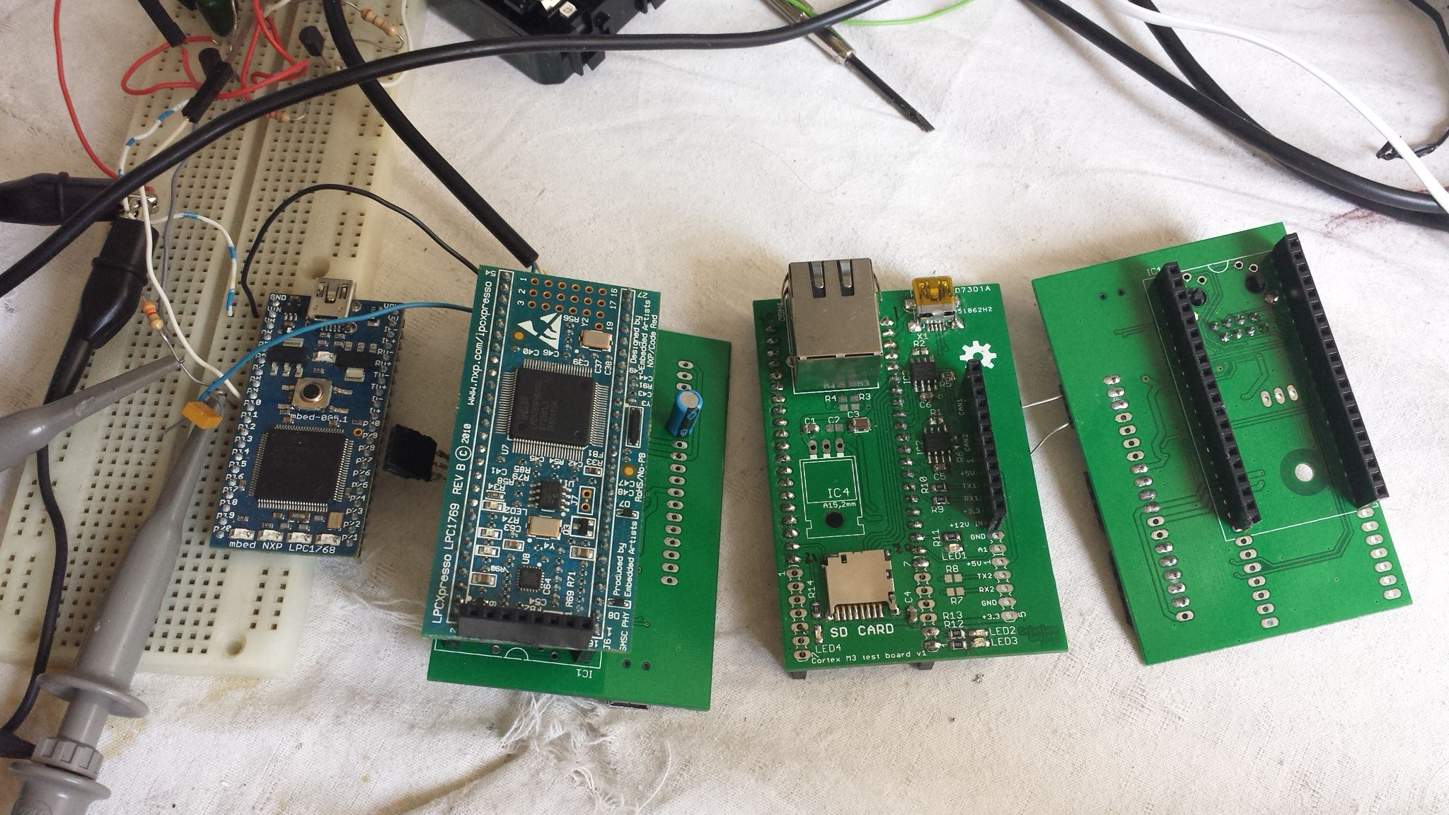
Hi Mark, I'd like to throw my 2 cents to the discussion. I'm a professional developer specialized in automotive bus reverse engineeging, in the past I worked for an automotive diagnostic company and later for another company that developed electric car conversion kits, and now I'm the technical director @ eV-Now! foundation Italy. A while ago I was developing an open source ECU that would allow anyone to do the CAN bus study with the CAN-USB function and then program the same device to be an ECU emulator to simulate the presence of a combustion engine in a converted electric car. Unfortunately, the project was put on standby for various reasons.
The board, as you can see in the picture, is just an expansion board for the awesome MBED project (www.mbed.org ) and features an sd card slot, 2 CAN transceivers, an ethernet port and an USB device port. The MBED is awesome because it offers a lot of cool libraries and even a ready to use and free RTOS; there is even a library to connect a 3G modem to the usb host port of the mcu. The compiler is online and allows an easy management of the project with an integrated cvs system, and if you don't like it, switching to the offline (proprietary :( but some open source alternatives based on gcc are already available) IDE is as easy as downloading the source file. A demo board that is fully compatible with the MBED is available from http://www.embeddedartists.com/products/ lpcxpresso/lpc1769_xpr.php , and that includes a programmer and debugger for less than the price of the PICKIT alone. I know that switching from a well known platform to ARM may seem like a very hard choice, I was a PIC lover too, but the MBED library greatly reduces the effort of porting the code to the new device. For example, adding an usb serial port is this easy:
#include "mbed.h"
#include "USBSerial.h"
//Virtual serial port over USB
USBSerial serial;
int main(void) {
while(1)
{ serial.printf("I am a virtual serial port\r\n");
wait(1);
}
}
So, IMHO, basing the OVMS v3 on the LPC1769 will solve the code space problem and transform it into an integrated CAN bus developing tool, providing some cool features at the same time like more power an memory, sd card data logging and dual CAN channels, for a price per MCU just slightly higher than the PIC solution. Another advantage is that we can develop a nice GUI that will help the user for the initial configuration of the SIM card connecting the OVMS to the USB port.
On the topic of the protocol, I agree on the CAN232 data format, I have that device too and all the software I've written is compatible with that protocol API (I may consider sharing some in the future, but it's very hacked together and specific for my job). Also, friends from the linux community have already integrated the support on the socketcan driver, and provided a very nice comparison of different devices APIs here: ftp://ftp.heanet.ie/ disk1/sourceforge/s/so/socketcan.berlios/SLCAN-API.pdf I think that it will be a breeze to implement that protocol, and I can help making it happen for very cheap (or even for free if I find some spare time and motivation), on the mbed platform.
Let me know if you need a PCB to test, I have some spare ones that you can solder components on, but as (I seem to understand that) you are based on hong kong, it may be cheaper to reproduce them locally from gerbers than to ship them from here.
Regards
Cristiano
Il giorno 29/ago/2013 03:25, "Mark Webb-Johnson" <mark@webb- johnson.net> ha scritto:
P.S. What I would really like to do is get the OVMS CAN-USB adaptor working, and then give those out in large quantities. The more people decoding vehicle CAN communications, the more cars become open vehicles. But, to do that I need some one / people to step forward and help with this. The China manufacturer is standing by and asking me for the circuit diagram, but I've got too much on my plate at the moment to take on the CAN-USB hardware and firmware as well. Using a PIC32 microprocessor (with built-in USB support), and MCP2551 CAN controller, we can do this for a materials cost perhaps around US$30 (vs US$150 retail for the cheapest commercial units). I'll send out a separate 'appeal' for this, and see if anyone will step forward to help.
(changed subject, to better reflect what this discussion is about) Wow, I feel really privileged to have Brian and Mastro involved in this discussion (given both your backgrounds). Thanks for your time and support, guys. Regarding ARM vs PIC, I really have no preference. Looking at the LPC1769 referenced, it has 512KB flash and 64KB RAM, running at 12MHz, with 4xUART, 2xCAN and USB. US$26. Looking at the UWB32 (PIC32MX795), it has 512KB flash, 128KB RAM, running at 80MHz, with 6xUART, 2xCAN and USB. US$40. That said, we wouldn't be using either board directly, so it is probably fairer to compare raw processor prices, and they both seem to cost about the same and have about the same capabilities. Quite frankly, 512KB flash in a 32bit platform, vs 96KB flash in an 8bit platform, is not going to make a lot of difference long-term. Sure, we'll have more flash space initially (but remember 32bit code takes up more space then 8bit code), but we'll eventually outgrow it. The extra RAM space will make a difference (64KB/128KB vs 3KB now!). The ability to upload new firmware via USB is a must, as it will allow us to have vehicle-specific firmware and make the most of the available space. From the development environment point of view, I don't like either :-( I would really much prefer a completely open source GCC based toolchain - something not crippled by commercial restrictions or dumbed-down for entry level work. Microchip recently changed their policy on the windows compiler, that bit us, and the PIC32 development tools have limited optimisation unless you buy the commercial product. MBED looks good, but seems to suffer from the same sort of issue - although I haven't had time yet to go into detail with this. Both the PIC and MBED libraries look good, but MBED seems easier to work with. Anyway, back to the topic at hand, I really want to separate the OVMS v3 project from this simple CAN-USB. Most certainly, the OVMS v3 hardware will have support for CAN BUS logging (most likely to removable flash card, or over the network), but that is a separate discussion to this. What I hope to create here is a very very simple very very cheap device. Something you could build yourself for perhaps US$20-30 parts, or get it retail for perhaps US$40-50. Something that just does this one job, but does it simply and cleanly. Something we can get sponsorship for to give away for free in large numbers, or just to incentivise people or 'seed' the idea of reverse engineering vehicle CAN buses. Regards, Mark. On 3 Sep, 2013, at 6:24 AM, HONDA S-2000 <s2000@sounds.wa.com> wrote:
How much is your CAN expansion board for the MBED?
I'm not sure what the difference is between the LPC1769 that you recommend and the LPC1768 that MBED lists as currently available. One obvious difference is that the LPC1769 is about US$118. The LPC1768 is $49
http://mbed.org/handbook/Order
My concern is that by the time you make the CAN expansion board, with all the costs associated with that, you might as well put the main CPU on the same board and not be stuck buying a retail platform. Buying two boards is surely going to cost more than one, unless there is something tricky like radio antenna design involved.
As for PIC versus ARM or even AVR or MSP430, it doesn't really matter what the processor is. All of these CPU chips have $49 or even $5 (MSP430) evaluation boards and device support libraries.
Brian Willoughby Sound Consulting
On Sep 2, 2013, at 04:11, Mastro Gippo wrote:
Hi Mark, I'd like to throw my 2 cents to the discussion. I'm a professional developer specialized in automotive bus reverse engineeging, in the past I worked for an automotive diagnostic company and later for another company that developed electric car conversion kits, and now I'm the technical director @ eV-Now! foundation Italy. A while ago I was developing an open source ECU that would allow anyone to do the CAN bus study with the CAN-USB function and then program the same device to be an ECU emulator to simulate the presence of a combustion engine in a converted electric car. Unfortunately, the project was put on standby for various reasons.
The board, as you can see in the picture, is just an expansion board for the awesome MBED project (www.mbed.org ) and features an sd card slot, 2 CAN transceivers, an ethernet port and an USB device port. The MBED is awesome because it offers a lot of cool libraries and even a ready to use and free RTOS; there is even a library to connect a 3G modem to the usb host port of the mcu. The compiler is online and allows an easy management of the project with an integrated cvs system, and if you don't like it, switching to the offline (proprietary :( but some open source alternatives based on gcc are already available) IDE is as easy as downloading the source file. A demo board that is fully compatible with the MBED is available from http://www.embeddedartists.com/products/lpcxpresso/lpc1769_xpr.php , and that includes a programmer and debugger for less than the price of the PICKIT alone. I know that switching from a well known platform to ARM may seem like a very hard choice, I was a PIC lover too, but the MBED library greatly reduces the effort of porting the code to the new device. For example, adding an usb serial port is this easy:
#include "mbed.h"
#include "USBSerial.h"
//Virtual serial port over USB
USBSerial serial;
int main(void) {
while(1)
{ serial.printf("I am a virtual serial port\r\n");
wait(1);
}
}
So, IMHO, basing the OVMS v3 on the LPC1769 will solve the code space problem and transform it into an integrated CAN bus developing tool, providing some cool features at the same time like more power an memory, sd card data logging and dual CAN channels, for a price per MCU just slightly higher than the PIC solution. Another advantage is that we can develop a nice GUI that will help the user for the initial configuration of the SIM card connecting the OVMS to the USB port.
On the topic of the protocol, I agree on the CAN232 data format, I have that device too and all the software I've written is compatible with that protocol API (I may consider sharing some in the future, but it's very hacked together and specific for my job). Also, friends from the linux community have already integrated the support on the socketcan driver, and provided a very nice comparison of different devices APIs here: ftp://ftp.heanet.ie/disk1/sourceforge/s/so/socketcan.berlios/SLCAN-API.pdf I think that it will be a breeze to implement that protocol, and I can help making it happen for very cheap (or even for free if I find some spare time and motivation), on the mbed platform.
Let me know if you need a PCB to test, I have some spare ones that you can solder components on, but as (I seem to understand that) you are based on hong kong, it may be cheaper to reproduce them locally from gerbers than to ship them from here.
Regards
Cristiano
Il giorno 29/ago/2013 03:25, "Mark Webb-Johnson" <mark@webb-johnson.net> ha scritto:
P.S. What I would really like to do is get the OVMS CAN-USB adaptor working, and then give those out in large quantities. The more people decoding vehicle CAN communications, the more cars become open vehicles. But, to do that I need some one / people to step forward and help with this. The China manufacturer is standing by and asking me for the circuit diagram, but I've got too much on my plate at the moment to take on the CAN-USB hardware and firmware as well. Using a PIC32 microprocessor (with built-in USB support), and MCP2551 CAN controller, we can do this for a materials cost perhaps around US$30 (vs US$150 retail for the cheapest commercial units). I'll send out a separate 'appeal' for this, and see if anyone will step forward to help.
OvmsDev mailing list OvmsDev@lists.teslaclub.hk http://lists.teslaclub.hk/mailman/listinfo/ovmsdev
On the topic of support libraries, Microchip has several application notes for CAN. These aren't necessary the only ones, or even the most appropriate for the PIC32, but they're some I had lying around. AN853 - PIC18XXX8 CAN Driver with Prioritized Transmit Buffer AN930 - J1939 C Library for CAN-Enabled PICmicro Microcontrollers AN945 - A CANopen Stack for PIC18 ECAN Microcontrollers As for optimization, I looked carefully at the (older) Microchip compiler for the PIC18, and found no real significant advantage to the optimized output. I decided to recommend that my client not bother with the license, since they were seriously strapped for cash. I looked at the assembly output for both optimized and unoptimized (using the time-limited demo of the full product), and although they produced different code, it wasn't exactly a night-and-day difference. Both versions seemed to miss out on optimizations that I could make with hand assembly. Also, the optimized version which used the alternate PIC18 C extensions did not noticeably improve the code or make it smaller. The most important optimization that can be done is intelligent coding at the C level. Many programmers waste resources using float on an 8-bit that doesn't have direct support, or they repeat operations thousands of times unnecessarily. These sorts of problems cannot be fixed by an optimizing compiler, and they're much more of a problem. If we're going to consider ARM, then I suggest that someone take the time to find out what chips (or circuits) are good candidates for the voltage translation. My hunch is that I/O pins on the ARM do not directly connect to the 12V CAN bus, especially considering that transients of more than 40V might appear. That said, perhaps an ARM solution can be accomplished with the same low chip count as the proposed PIC32 solution. Brian Willoughby Sound Consulting On Sep 2, 2013, at 18:10, Mark Webb-Johnson wrote:
From the development environment point of view, I don't like either :-( I would really much prefer a completely open source GCC based toolchain - something not crippled by commercial restrictions or dumbed-down for entry level work. Microchip recently changed their policy on the windows compiler, that bit us, and the PIC32 development tools have limited optimisation unless you buy the commercial product. MBED looks good, but seems to suffer from the same sort of issue - although I haven't had time yet to go into detail with this. Both the PIC and MBED libraries look good, but MBED seems easier to work with.
Anyway, back to the topic at hand, I really want to separate the OVMS v3 project from this simple CAN-USB. Most certainly, the OVMS v3 hardware will have support for CAN BUS logging (most likely to removable flash card, or over the network), but that is a separate discussion to this. What I hope to create here is a very very simple very very cheap device. Something you could build yourself for perhaps US$20-30 parts, or get it retail for perhaps US$40-50. Something that just does this one job, but does it simply and cleanly. Something we can get sponsorship for to give away for free in large numbers, or just to incentivise people or 'seed' the idea of reverse engineering vehicle CAN buses.
Regards, Mark.
2013/9/4 HONDA S-2000 <s2000@sounds.wa.com>:
If we're going to consider ARM, then I suggest that someone take the time to find out what chips (or circuits) are good candidates for the voltage translation. My hunch is that I/O pins on the ARM do not directly connect to the 12V CAN bus, especially considering that transients of more than 40V might appear. That said, perhaps an ARM solution can be accomplished with the same low chip count as the proposed PIC32 solution.
What are you talking about? No mcu connects directly to these voltages, they all need a transceiver. Also, there is no way we can effectively replace the 2551 with passives.. On the other hand, there are a bunch of equivalents out there from major companies like TI, that may or may not cost less. I'd say that the usb connector+MCU+mcp2551+a bunch of passives and a crystal is all we need, now it's just a matter of choosing the right mcu. MG
I'm used to the mcp2551, but it is a 5V device. The pic32mx795 has both CAN port pins 5V tolerant, and levels for tx seem sufficient for mcp2551 to rx. The 5V is not too much of an issue, as we have that from USB, but it would be good to be just 3.3V. Anyone know of a 3.3V equivalent to the mcp2551? SN65HVD233? Or, just stay with mcp2551? Regards, Mark
On 4 Sep, 2013, at 4:02 pm, Mastro Gippo <gipmad@gmail.com> wrote:
2013/9/4 HONDA S-2000 <s2000@sounds.wa.com>:
If we're going to consider ARM, then I suggest that someone take the time to find out what chips (or circuits) are good candidates for the voltage translation. My hunch is that I/O pins on the ARM do not directly connect to the 12V CAN bus, especially considering that transients of more than 40V might appear. That said, perhaps an ARM solution can be accomplished with the same low chip count as the proposed PIC32 solution.
What are you talking about? No mcu connects directly to these voltages, they all need a transceiver. Also, there is no way we can effectively replace the 2551 with passives.. On the other hand, there are a bunch of equivalents out there from major companies like TI, that may or may not cost less. I'd say that the usb connector+MCU+mcp2551+a bunch of passives and a crystal is all we need, now it's just a matter of choosing the right mcu.
MG _______________________________________________ OvmsDev mailing list OvmsDev@lists.teslaclub.hk http://lists.teslaclub.hk/mailman/listinfo/ovmsdev
I'd say that the best choice is the SN65HVD233, but both in the OVMS and in the USB-CAN converter we already have 5V for the modem and from the USB, so we don't save an LDO.It should be just a matter of price in the end. MG 2013/9/4 Mark Webb-Johnson <mark@webb-johnson.net>:
I'm used to the mcp2551, but it is a 5V device. The pic32mx795 has both CAN port pins 5V tolerant, and levels for tx seem sufficient for mcp2551 to rx. The 5V is not too much of an issue, as we have that from USB, but it would be good to be just 3.3V.
Anyone know of a 3.3V equivalent to the mcp2551? SN65HVD233? Or, just stay with mcp2551?
Regards, Mark
On 4 Sep, 2013, at 4:02 pm, Mastro Gippo <gipmad@gmail.com> wrote:
2013/9/4 HONDA S-2000 <s2000@sounds.wa.com>:
If we're going to consider ARM, then I suggest that someone take the time to find out what chips (or circuits) are good candidates for the voltage translation. My hunch is that I/O pins on the ARM do not directly connect to the 12V CAN bus, especially considering that transients of more than 40V might appear. That said, perhaps an ARM solution can be accomplished with the same low chip count as the proposed PIC32 solution.
What are you talking about? No mcu connects directly to these voltages, they all need a transceiver. Also, there is no way we can effectively replace the 2551 with passives.. On the other hand, there are a bunch of equivalents out there from major companies like TI, that may or may not cost less. I'd say that the usb connector+MCU+mcp2551+a bunch of passives and a crystal is all we need, now it's just a matter of choosing the right mcu.
MG _______________________________________________ OvmsDev mailing list OvmsDev@lists.teslaclub.hk http://lists.teslaclub.hk/mailman/listinfo/ovmsdev
OvmsDev mailing list OvmsDev@lists.teslaclub.hk http://lists.teslaclub.hk/mailman/listinfo/ovmsdev
The MCP2551 requires a minimum Vdd of 4.5V to ensure ISO-11898 specifications, but USB Vbus is only guaranteed to be 4.01V under certain conditions like at the end of a bus-powered hub. There are small 5V boost regulators that work with minimal passives, some even with just capacitors and no inductors, but it will add to the size and cost. Maybe the SN65HVD233 is a better choice. It only tolerates 36V spikes, not 42V, but I have no idea how likely either of those high voltages are on a CAN bus in real vehicles. The SN65HVD233 will tolerate 7V on Vcc, but 3.6V is the maximum recommended. I almost suggested that it should run directly from USB Vbus, but that is perhaps not wise. I'm sure the 3.3V LDO will handle the load of the CPU and CAN transceiver. Brian On Sep 4, 2013, at 06:49, Mark Webb-Johnson wrote:
I'm used to the mcp2551, but it is a 5V device. The pic32mx795 has both CAN port pins 5V tolerant, and levels for tx seem sufficient for mcp2551 to rx. The 5V is not too much of an issue, as we have that from USB, but it would be good to be just 3.3V.
Anyone know of a 3.3V equivalent to the mcp2551? SN65HVD233? Or, just stay with mcp2551?
Sorry Brian, I misunderstood what you said, english is not my main language. As for the mcp2551, it's just a transceiver, you don't need any libraries. The can logic is embedded in the device. That said, on the mbed the library allows you to just declare a CAN channel with CAN can1(p9, p10); and write a message with : can1.write(CANMessage(1337, &counter, 1)); see the example on http://mbed.org/handbook/CAN Regards MG 2013/9/4 HONDA S-2000 <s2000@sounds.wa.com>:
The MCP2551 requires a minimum Vdd of 4.5V to ensure ISO-11898 specifications, but USB Vbus is only guaranteed to be 4.01V under certain conditions like at the end of a bus-powered hub.
There are small 5V boost regulators that work with minimal passives, some even with just capacitors and no inductors, but it will add to the size and cost.
Maybe the SN65HVD233 is a better choice. It only tolerates 36V spikes, not 42V, but I have no idea how likely either of those high voltages are on a CAN bus in real vehicles.
The SN65HVD233 will tolerate 7V on Vcc, but 3.6V is the maximum recommended. I almost suggested that it should run directly from USB Vbus, but that is perhaps not wise. I'm sure the 3.3V LDO will handle the load of the CPU and CAN transceiver.
Brian
On Sep 4, 2013, at 06:49, Mark Webb-Johnson wrote:
I'm used to the mcp2551, but it is a 5V device. The pic32mx795 has both CAN port pins 5V tolerant, and levels for tx seem sufficient for mcp2551 to rx. The 5V is not too much of an issue, as we have that from USB, but it would be good to be just 3.3V.
Anyone know of a 3.3V equivalent to the mcp2551? SN65HVD233? Or, just stay with mcp2551?
_______________________________________________ OvmsDev mailing list OvmsDev@lists.teslaclub.hk http://lists.teslaclub.hk/mailman/listinfo/ovmsdev
Looking at the wholesale pricing, and given that we have 5V already and lots of experience with MCP2551, I think I'll stick with that for the initial design and then see what the factory says. At the moment, I'm trying to make a rough design using PIC32MX795F512H+MCP2551 - DB9 at one end, USB at the other. No final decision on microcontroller yet, but I just want to get something to the factory to firm up estimates on what this is going to cost. I'll tell the factory that the SN65HVD233 is an option for them, if it is easier/cheaper. The PIC32 is completely overkill for this, and will most likely be 50% of the BOM cost. But, I really want lots of RAM on this thing. If we drop RAM requirement to 64KB, we can save a few bucks, but it really doesn't seem worthwhile. Regarding the oscillator, every design I've ever done uses an external oscillator. I know the PICs (and others now) have internal FSCs, but am concerned about timing accuracies for CAN and USB. The data sheet says the internal FSC can be used for USB (and incidentally is always used for 48MHz USB when in suspend mode). Anyone have any experience with this? My gut feeling is to wire the board for an 8MHz external crystal (and two caps), and then see if we can get it working reliably with that disabled. If we end up not needing it, we can leave it unpopulated at manufacture time (saving a buck). Regards, Mark. On 5 Sep, 2013, at 4:01 AM, HONDA S-2000 <s2000@sounds.wa.com> wrote:
The MCP2551 requires a minimum Vdd of 4.5V to ensure ISO-11898 specifications, but USB Vbus is only guaranteed to be 4.01V under certain conditions like at the end of a bus-powered hub.
There are small 5V boost regulators that work with minimal passives, some even with just capacitors and no inductors, but it will add to the size and cost.
Maybe the SN65HVD233 is a better choice. It only tolerates 36V spikes, not 42V, but I have no idea how likely either of those high voltages are on a CAN bus in real vehicles.
The SN65HVD233 will tolerate 7V on Vcc, but 3.6V is the maximum recommended. I almost suggested that it should run directly from USB Vbus, but that is perhaps not wise. I'm sure the 3.3V LDO will handle the load of the CPU and CAN transceiver.
Brian
On Sep 4, 2013, at 06:49, Mark Webb-Johnson wrote:
I'm used to the mcp2551, but it is a 5V device. The pic32mx795 has both CAN port pins 5V tolerant, and levels for tx seem sufficient for mcp2551 to rx. The 5V is not too much of an issue, as we have that from USB, but it would be good to be just 3.3V.
Anyone know of a 3.3V equivalent to the mcp2551? SN65HVD233? Or, just stay with mcp2551?
_______________________________________________ OvmsDev mailing list OvmsDev@lists.teslaclub.hk http://lists.teslaclub.hk/mailman/listinfo/ovmsdev
I like the MCP2551, but I don't think it's guaranteed to work without a 5V boost regulator. The USB specifications are clear that the 4.5V minimum needed is not always guaranteed to be present. As for the crystal, it's all about the accuracy of the internal oscillator. USB calls out a precision in the specification, and as long as you meet that you're fine. Older chips had an internal oscillator that was not precise enough. This newer PIC32MX796 has a 0.9% oscillator, meaning that it's plenty accurate enough for USB. I trust Microchip, in that they don't claim their internal oscillator will work for chips that can't do it, but this one can. That said, there's nothing wrong with putting the traces on the board (other than the space they take up). I'm partial to smaller SMD parts like the ECS ECS-120-20-30B-DU, but those are more expensive than the large canned crystals. Does the CAN spec (ISO-11898) say what the required precision is for the clock? The SN65HVD235 has a bus listen-only feature that seems like a really safe option for a project like this. I imagine that the device will mostly be listening to CAN messages and not attempting to inject potentially dangerous messages into an unknown vehicle. Supposedly, the listen feature also helps with autobaud. Brian On Sep 4, 2013, at 19:22, Mark Webb-Johnson wrote:
Looking at the wholesale pricing, and given that we have 5V already and lots of experience with MCP2551, I think I'll stick with that for the initial design and then see what the factory says.
At the moment, I'm trying to make a rough design using PIC32MX795F512H+MCP2551 - DB9 at one end, USB at the other. No final decision on microcontroller yet, but I just want to get something to the factory to firm up estimates on what this is going to cost. I'll tell the factory that the SN65HVD233 is an option for them, if it is easier/cheaper.
The PIC32 is completely overkill for this, and will most likely be 50% of the BOM cost. But, I really want lots of RAM on this thing. If we drop RAM requirement to 64KB, we can save a few bucks, but it really doesn't seem worthwhile.
Regarding the oscillator, every design I've ever done uses an external oscillator. I know the PICs (and others now) have internal FSCs, but am concerned about timing accuracies for CAN and USB. The data sheet says the internal FSC can be used for USB (and incidentally is always used for 48MHz USB when in suspend mode). Anyone have any experience with this? My gut feeling is to wire the board for an 8MHz external crystal (and two caps), and then see if we can get it working reliably with that disabled. If we end up not needing it, we can leave it unpopulated at manufacture time (saving a buck).
Regards, Mark.
On 5 Sep, 2013, at 4:01 AM, HONDA S-2000 <s2000@sounds.wa.com> wrote:
The MCP2551 requires a minimum Vdd of 4.5V to ensure ISO-11898 specifications, but USB Vbus is only guaranteed to be 4.01V under certain conditions like at the end of a bus-powered hub.
Just a quick request: there should be enough space on the pcb to add a bluetooth module. Please add at least the footprint for [http://www.ebay.it/sch/i.html?_odkw=hc-05&_sop=15&_osacat=0&_from=R40&LH_Pre...] This would add the need for an independent power supply, but as I recall you were already planning to place the footprints on the pcb. I found myself in need for a wireless connection a lot of times, usually to get a quick log with my phone. For example, this weekend I'm doing a few tests with a tesla model s and I'd love a more stealth method to get the data. About being stealth, I found myself using ELM327 adapters to get CAN data more than a few times, but I have to include a lot of filtering due to the slowness of the adapter. That said, the STN1170 is an "elm327 on steroids", and may have enough horsepower to log unfiltered can data, while being a very good diagnostic tool to interface with Torque. http://batman.homelinux.com/blog/stn1170-bluetooth-obdii-adapter/ I still have not tested it, but maybe will soon. Single chips are available for 10$ in single quantities. Regards MG 2013/9/5 HONDA S-2000 <s2000@sounds.wa.com>:
I like the MCP2551, but I don't think it's guaranteed to work without a 5V boost regulator. The USB specifications are clear that the 4.5V minimum needed is not always guaranteed to be present.
As for the crystal, it's all about the accuracy of the internal oscillator. USB calls out a precision in the specification, and as long as you meet that you're fine. Older chips had an internal oscillator that was not precise enough. This newer PIC32MX796 has a 0.9% oscillator, meaning that it's plenty accurate enough for USB. I trust Microchip, in that they don't claim their internal oscillator will work for chips that can't do it, but this one can.
That said, there's nothing wrong with putting the traces on the board (other than the space they take up). I'm partial to smaller SMD parts like the ECS ECS-120-20-30B-DU, but those are more expensive than the large canned crystals.
Does the CAN spec (ISO-11898) say what the required precision is for the clock?
The SN65HVD235 has a bus listen-only feature that seems like a really safe option for a project like this. I imagine that the device will mostly be listening to CAN messages and not attempting to inject potentially dangerous messages into an unknown vehicle. Supposedly, the listen feature also helps with autobaud.
Brian
On Sep 4, 2013, at 19:22, Mark Webb-Johnson wrote:
Looking at the wholesale pricing, and given that we have 5V already and lots of experience with MCP2551, I think I'll stick with that for the initial design and then see what the factory says.
At the moment, I'm trying to make a rough design using PIC32MX795F512H+MCP2551 - DB9 at one end, USB at the other. No final decision on microcontroller yet, but I just want to get something to the factory to firm up estimates on what this is going to cost. I'll tell the factory that the SN65HVD233 is an option for them, if it is easier/cheaper.
The PIC32 is completely overkill for this, and will most likely be 50% of the BOM cost. But, I really want lots of RAM on this thing. If we drop RAM requirement to 64KB, we can save a few bucks, but it really doesn't seem worthwhile.
Regarding the oscillator, every design I've ever done uses an external oscillator. I know the PICs (and others now) have internal FSCs, but am concerned about timing accuracies for CAN and USB. The data sheet says the internal FSC can be used for USB (and incidentally is always used for 48MHz USB when in suspend mode). Anyone have any experience with this? My gut feeling is to wire the board for an 8MHz external crystal (and two caps), and then see if we can get it working reliably with that disabled. If we end up not needing it, we can leave it unpopulated at manufacture time (saving a buck).
Regards, Mark.
On 5 Sep, 2013, at 4:01 AM, HONDA S-2000 <s2000@sounds.wa.com> wrote:
The MCP2551 requires a minimum Vdd of 4.5V to ensure ISO-11898 specifications, but USB Vbus is only guaranteed to be 4.01V under certain conditions like at the end of a bus-powered hub.
_______________________________________________ OvmsDev mailing list OvmsDev@lists.teslaclub.hk http://lists.teslaclub.hk/mailman/listinfo/ovmsdev
I seem to recall that Mark wanted to keep the CAN-USB simple and cheap. Adding space for a Bluetooth module could double the size and cost of the PCB. It's not an 8-pin IC. Is there any reason you can't use the OVMS v3 for whatever you want the Bluetooth for? The CAN-USB is supposed to be a single-function, cheap, giveaway piece of electronics. Brian On Sep 6, 2013, at 00:52, Mastro Gippo wrote:
Just a quick request: there should be enough space on the pcb to add a bluetooth module. Please add at least the footprint for [http://www.ebay.it/sch/i.html? _odkw=hc-05&_sop=15&_osacat=0&_from=R40&LH_PrefLoc=2&_trksid=p2045573. m570.l1313&_nkw=hc-05+-74hc05&_sacat=0] This would add the need for an independent power supply, but as I recall you were already planning to place the footprints on the pcb. I found myself in need for a wireless connection a lot of times, usually to get a quick log with my phone. For example, this weekend I'm doing a few tests with a tesla model s and I'd love a more stealth method to get the data. About being stealth, I found myself using ELM327 adapters to get CAN data more than a few times, but I have to include a lot of filtering due to the slowness of the adapter. That said, the STN1170 is an "elm327 on steroids", and may have enough horsepower to log unfiltered can data, while being a very good diagnostic tool to interface with Torque. http://batman.homelinux.com/blog/stn1170-bluetooth-obdii- adapter/ I still have not tested it, but maybe will soon. Single chips are available for 10$ in single quantities.
Well, the idea was to just add the dip header, it doesn't waste much space because the bt module "floats" above the pcb (see the pics on the ebay link). Well, I think that it would be a good idea to bring out at least some of the unused pins to a header, to allow hacking and customization, it would add a lot of value for cheap. Like in the ovsm! :) MG Il giorno 06/set/2013 22:44, "HONDA S-2000" <s2000@sounds.wa.com> ha scritto:
I seem to recall that Mark wanted to keep the CAN-USB simple and cheap. Adding space for a Bluetooth module could double the size and cost of the PCB. It's not an 8-pin IC.
Is there any reason you can't use the OVMS v3 for whatever you want the Bluetooth for? The CAN-USB is supposed to be a single-function, cheap, giveaway piece of electronics.
Brian
On Sep 6, 2013, at 00:52, Mastro Gippo wrote:
Just a quick request: there should be enough space on the pcb to add a bluetooth module. Please add at least the footprint for [http://www.ebay.it/sch/i.**html?_odkw=hc-05&_sop=15&_** osacat=0&_from=R40&LH_PrefLoc=**2&_trksid=p2045573.m570.l1313&** _nkw=hc-05+-74hc05&_sacat=0<http://www.ebay.it/sch/i.html?_odkw=hc-05&_sop=15&_osacat=0&_from=R40&LH_PrefLoc=2&_trksid=p2045573.m570.l1313&_nkw=hc-05+-74hc05&_sacat=0> ] This would add the need for an independent power supply, but as I recall you were already planning to place the footprints on the pcb. I found myself in need for a wireless connection a lot of times, usually to get a quick log with my phone. For example, this weekend I'm doing a few tests with a tesla model s and I'd love a more stealth method to get the data. About being stealth, I found myself using ELM327 adapters to get CAN data more than a few times, but I have to include a lot of filtering due to the slowness of the adapter. That said, the STN1170 is an "elm327 on steroids", and may have enough horsepower to log unfiltered can data, while being a very good diagnostic tool to interface with Torque. http://batman.homelinux.com/**blog/stn1170-bluetooth-obdii-** adapter/<http://batman.homelinux.com/blog/stn1170-bluetooth-obdii-adapter/> I still have not tested it, but maybe will soon. Single chips are available for 10$ in single quantities.
______________________________**_________________ OvmsDev mailing list OvmsDev@lists.teslaclub.hk http://lists.teslaclub.hk/**mailman/listinfo/ovmsdev<http://lists.teslaclub.hk/mailman/listinfo/ovmsdev>
I'll try . It'll depend on space in the housing. I've got a few I've been playing with. I like the ones that direct solder: http://www.fasttech.com/products/0/10004051/1292002-ti-cc2540-bluetooth-40-b... http://www.fasttech.com/products/0/10003385/1251502-jy-mcu-hc-06-bluetooth-t... But the plug-in ones may be better suited as they can be entirely optional: http://www.fasttech.com/products/0/10001791/1129201-jy-mcu-hc-06-bluetooth-w... Regards, Mark. On 6 Sep, 2013, at 3:52 PM, Mastro Gippo <gipmad@gmail.com> wrote:
Just a quick request: there should be enough space on the pcb to add a bluetooth module. Please add at least the footprint for [http://www.ebay.it/sch/i.html?_odkw=hc-05&_sop=15&_osacat=0&_from=R40&LH_Pre...] This would add the need for an independent power supply, but as I recall you were already planning to place the footprints on the pcb. I found myself in need for a wireless connection a lot of times, usually to get a quick log with my phone. For example, this weekend I'm doing a few tests with a tesla model s and I'd love a more stealth method to get the data. About being stealth, I found myself using ELM327 adapters to get CAN data more than a few times, but I have to include a lot of filtering due to the slowness of the adapter. That said, the STN1170 is an "elm327 on steroids", and may have enough horsepower to log unfiltered can data, while being a very good diagnostic tool to interface with Torque. http://batman.homelinux.com/blog/stn1170-bluetooth-obdii-adapter/ I still have not tested it, but maybe will soon. Single chips are available for 10$ in single quantities.
Regards MG
2013/9/5 HONDA S-2000 <s2000@sounds.wa.com>:
I like the MCP2551, but I don't think it's guaranteed to work without a 5V boost regulator. The USB specifications are clear that the 4.5V minimum needed is not always guaranteed to be present.
As for the crystal, it's all about the accuracy of the internal oscillator. USB calls out a precision in the specification, and as long as you meet that you're fine. Older chips had an internal oscillator that was not precise enough. This newer PIC32MX796 has a 0.9% oscillator, meaning that it's plenty accurate enough for USB. I trust Microchip, in that they don't claim their internal oscillator will work for chips that can't do it, but this one can.
That said, there's nothing wrong with putting the traces on the board (other than the space they take up). I'm partial to smaller SMD parts like the ECS ECS-120-20-30B-DU, but those are more expensive than the large canned crystals.
Does the CAN spec (ISO-11898) say what the required precision is for the clock?
The SN65HVD235 has a bus listen-only feature that seems like a really safe option for a project like this. I imagine that the device will mostly be listening to CAN messages and not attempting to inject potentially dangerous messages into an unknown vehicle. Supposedly, the listen feature also helps with autobaud.
Brian
On Sep 4, 2013, at 19:22, Mark Webb-Johnson wrote:
Looking at the wholesale pricing, and given that we have 5V already and lots of experience with MCP2551, I think I'll stick with that for the initial design and then see what the factory says.
At the moment, I'm trying to make a rough design using PIC32MX795F512H+MCP2551 - DB9 at one end, USB at the other. No final decision on microcontroller yet, but I just want to get something to the factory to firm up estimates on what this is going to cost. I'll tell the factory that the SN65HVD233 is an option for them, if it is easier/cheaper.
The PIC32 is completely overkill for this, and will most likely be 50% of the BOM cost. But, I really want lots of RAM on this thing. If we drop RAM requirement to 64KB, we can save a few bucks, but it really doesn't seem worthwhile.
Regarding the oscillator, every design I've ever done uses an external oscillator. I know the PICs (and others now) have internal FSCs, but am concerned about timing accuracies for CAN and USB. The data sheet says the internal FSC can be used for USB (and incidentally is always used for 48MHz USB when in suspend mode). Anyone have any experience with this? My gut feeling is to wire the board for an 8MHz external crystal (and two caps), and then see if we can get it working reliably with that disabled. If we end up not needing it, we can leave it unpopulated at manufacture time (saving a buck).
Regards, Mark.
On 5 Sep, 2013, at 4:01 AM, HONDA S-2000 <s2000@sounds.wa.com> wrote:
The MCP2551 requires a minimum Vdd of 4.5V to ensure ISO-11898 specifications, but USB Vbus is only guaranteed to be 4.01V under certain conditions like at the end of a bus-powered hub.
_______________________________________________ OvmsDev mailing list OvmsDev@lists.teslaclub.hk http://lists.teslaclub.hk/mailman/listinfo/ovmsdev
OvmsDev mailing list OvmsDev@lists.teslaclub.hk http://lists.teslaclub.hk/mailman/listinfo/ovmsdev

Hi, Just wanted to put my vote for adding an interface like bluetooth to the OVMS. There are several devices like phones and pads which may enjoy simple wireless access to the data available through the OVMS. One could also envision that a more sophisticated "carputer" would want to have network access through the cellular data in the OVMS. The mobile networks' data rates are increasing and prices falling, so one might even consider sharing a high speed connection if the OVMS could sustain this. Don't get me wrong, I do see an advantage to using the KISS methodology in this project, but just open it up a little by having a simple interface like bluetooth. Best regards Rolf On 07.09.2013 14:43, Mark Webb-Johnson wrote:
I'll try . It'll depend on space in the housing. I've got a few I've been playing with.
I like the ones that direct solder:
http://www.fasttech.com/products/0/10004051/1292002-ti-cc2540-bluetooth-40-b... http://www.fasttech.com/products/0/10003385/1251502-jy-mcu-hc-06-bluetooth-t...
But the plug-in ones may be better suited as they can be entirely optional:
http://www.fasttech.com/products/0/10001791/1129201-jy-mcu-hc-06-bluetooth-w...
Regards, Mark.
On 6 Sep, 2013, at 3:52 PM, Mastro Gippo <gipmad@gmail.com <mailto:gipmad@gmail.com>> wrote:
Just a quick request: there should be enough space on the pcb to add a bluetooth module. Please add at least the footprint for [http://www.ebay.it/sch/i.html?_odkw=hc-05&_sop=15&_osacat=0&_from=R40&LH_Pre...] This would add the need for an independent power supply, but as I recall you were already planning to place the footprints on the pcb. I found myself in need for a wireless connection a lot of times, usually to get a quick log with my phone. For example, this weekend I'm doing a few tests with a tesla model s and I'd love a more stealth method to get the data. About being stealth, I found myself using ELM327 adapters to get CAN data more than a few times, but I have to include a lot of filtering due to the slowness of the adapter. That said, the STN1170 is an "elm327 on steroids", and may have enough horsepower to log unfiltered can data, while being a very good diagnostic tool to interface with Torque. http://batman.homelinux.com/blog/stn1170-bluetooth-obdii-adapter/ I still have not tested it, but maybe will soon. Single chips are available for 10$ in single quantities.
Regards MG
2013/9/5 HONDA S-2000 <s2000@sounds.wa.com <mailto:s2000@sounds.wa.com>>:
I like the MCP2551, but I don't think it's guaranteed to work without a 5V boost regulator. The USB specifications are clear that the 4.5V minimum needed is not always guaranteed to be present.
As for the crystal, it's all about the accuracy of the internal oscillator. USB calls out a precision in the specification, and as long as you meet that you're fine. Older chips had an internal oscillator that was not precise enough. This newer PIC32MX796 has a 0.9% oscillator, meaning that it's plenty accurate enough for USB. I trust Microchip, in that they don't claim their internal oscillator will work for chips that can't do it, but this one can.
That said, there's nothing wrong with putting the traces on the board (other than the space they take up). I'm partial to smaller SMD parts like the ECS ECS-120-20-30B-DU, but those are more expensive than the large canned crystals.
Does the CAN spec (ISO-11898) say what the required precision is for the clock?
The SN65HVD235 has a bus listen-only feature that seems like a really safe option for a project like this. I imagine that the device will mostly be listening to CAN messages and not attempting to inject potentially dangerous messages into an unknown vehicle. Supposedly, the listen feature also helps with autobaud.
Brian
On Sep 4, 2013, at 19:22, Mark Webb-Johnson wrote:
Looking at the wholesale pricing, and given that we have 5V already and lots of experience with MCP2551, I think I'll stick with that for the initial design and then see what the factory says.
At the moment, I'm trying to make a rough design using PIC32MX795F512H+MCP2551 - DB9 at one end, USB at the other. No final decision on microcontroller yet, but I just want to get something to the factory to firm up estimates on what this is going to cost. I'll tell the factory that the SN65HVD233 is an option for them, if it is easier/cheaper.
The PIC32 is completely overkill for this, and will most likely be 50% of the BOM cost. But, I really want lots of RAM on this thing. If we drop RAM requirement to 64KB, we can save a few bucks, but it really doesn't seem worthwhile.
Regarding the oscillator, every design I've ever done uses an external oscillator. I know the PICs (and others now) have internal FSCs, but am concerned about timing accuracies for CAN and USB. The data sheet says the internal FSC can be used for USB (and incidentally is always used for 48MHz USB when in suspend mode). Anyone have any experience with this? My gut feeling is to wire the board for an 8MHz external crystal (and two caps), and then see if we can get it working reliably with that disabled. If we end up not needing it, we can leave it unpopulated at manufacture time (saving a buck).
Regards, Mark.
On 5 Sep, 2013, at 4:01 AM, HONDA S-2000 <s2000@sounds.wa.com <mailto:s2000@sounds.wa.com>> wrote:
The MCP2551 requires a minimum Vdd of 4.5V to ensure ISO-11898 specifications, but USB Vbus is only guaranteed to be 4.01V under certain conditions like at the end of a bus-powered hub.
_______________________________________________ OvmsDev mailing list OvmsDev@lists.teslaclub.hk <mailto:OvmsDev@lists.teslaclub.hk> http://lists.teslaclub.hk/mailman/listinfo/ovmsdev
OvmsDev mailing list OvmsDev@lists.teslaclub.hk <mailto:OvmsDev@lists.teslaclub.hk> http://lists.teslaclub.hk/mailman/listinfo/ovmsdev
_______________________________________________ OvmsDev mailing list OvmsDev@lists.teslaclub.hk http://lists.teslaclub.hk/mailman/listinfo/ovmsdev
-- Rolf Welde Skeie Solåsen 27, 5223 Nesttun, Norway +47 92403016 / rwskeie@gmail.com
Rolf, Do you mean to OVMS or CAN-USB? For the next iteration of OVMS hardware, I understand and thoroughly agree (apart from anything, I want it for my Parrot Asteroid), but not so sure about for the CAN-USB project. Regards, Mark. On 9 Sep, 2013, at 9:48 PM, Rolf Welde Skeie <rwskeie@gmail.com> wrote:
Hi,
Just wanted to put my vote for adding an interface like bluetooth to the OVMS. There are several devices like phones and pads which may enjoy simple wireless access to the data available through the OVMS. One could also envision that a more sophisticated "carputer" would want to have network access through the cellular data in the OVMS. The mobile networks' data rates are increasing and prices falling, so one might even consider sharing a high speed connection if the OVMS could sustain this. Don't get me wrong, I do see an advantage to using the KISS methodology in this project, but just open it up a little by having a simple interface like bluetooth.
Best regards Rolf
On 07.09.2013 14:43, Mark Webb-Johnson wrote:
I'll try . It'll depend on space in the housing. I've got a few I've been playing with.
I like the ones that direct solder:
http://www.fasttech.com/products/0/10004051/1292002-ti-cc2540-bluetooth-40-b... http://www.fasttech.com/products/0/10003385/1251502-jy-mcu-hc-06-bluetooth-t...
But the plug-in ones may be better suited as they can be entirely optional:
http://www.fasttech.com/products/0/10001791/1129201-jy-mcu-hc-06-bluetooth-w...
Regards, Mark.
On 6 Sep, 2013, at 3:52 PM, Mastro Gippo <gipmad@gmail.com <mailto:gipmad@gmail.com>> wrote:
Just a quick request: there should be enough space on the pcb to add a bluetooth module. Please add at least the footprint for [http://www.ebay.it/sch/i.html?_odkw=hc-05&_sop=15&_osacat=0&_from=R40&LH_Pre...] This would add the need for an independent power supply, but as I recall you were already planning to place the footprints on the pcb. I found myself in need for a wireless connection a lot of times, usually to get a quick log with my phone. For example, this weekend I'm doing a few tests with a tesla model s and I'd love a more stealth method to get the data. About being stealth, I found myself using ELM327 adapters to get CAN data more than a few times, but I have to include a lot of filtering due to the slowness of the adapter. That said, the STN1170 is an "elm327 on steroids", and may have enough horsepower to log unfiltered can data, while being a very good diagnostic tool to interface with Torque. http://batman.homelinux.com/blog/stn1170-bluetooth-obdii-adapter/ I still have not tested it, but maybe will soon. Single chips are available for 10$ in single quantities.
Regards MG
2013/9/5 HONDA S-2000 <s2000@sounds.wa.com <mailto:s2000@sounds.wa.com>>:
I like the MCP2551, but I don't think it's guaranteed to work without a 5V boost regulator. The USB specifications are clear that the 4.5V minimum needed is not always guaranteed to be present.
As for the crystal, it's all about the accuracy of the internal oscillator. USB calls out a precision in the specification, and as long as you meet that you're fine. Older chips had an internal oscillator that was not precise enough. This newer PIC32MX796 has a 0.9% oscillator, meaning that it's plenty accurate enough for USB. I trust Microchip, in that they don't claim their internal oscillator will work for chips that can't do it, but this one can.
That said, there's nothing wrong with putting the traces on the board (other than the space they take up). I'm partial to smaller SMD parts like the ECS ECS-120-20-30B-DU, but those are more expensive than the large canned crystals.
Does the CAN spec (ISO-11898) say what the required precision is for the clock?
The SN65HVD235 has a bus listen-only feature that seems like a really safe option for a project like this. I imagine that the device will mostly be listening to CAN messages and not attempting to inject potentially dangerous messages into an unknown vehicle. Supposedly, the listen feature also helps with autobaud.
Brian
On Sep 4, 2013, at 19:22, Mark Webb-Johnson wrote:
Looking at the wholesale pricing, and given that we have 5V already and lots of experience with MCP2551, I think I'll stick with that for the initial design and then see what the factory says.
At the moment, I'm trying to make a rough design using PIC32MX795F512H+MCP2551 - DB9 at one end, USB at the other. No final decision on microcontroller yet, but I just want to get something to the factory to firm up estimates on what this is going to cost. I'll tell the factory that the SN65HVD233 is an option for them, if it is easier/cheaper.
The PIC32 is completely overkill for this, and will most likely be 50% of the BOM cost. But, I really want lots of RAM on this thing. If we drop RAM requirement to 64KB, we can save a few bucks, but it really doesn't seem worthwhile.
Regarding the oscillator, every design I've ever done uses an external oscillator. I know the PICs (and others now) have internal FSCs, but am concerned about timing accuracies for CAN and USB. The data sheet says the internal FSC can be used for USB (and incidentally is always used for 48MHz USB when in suspend mode). Anyone have any experience with this? My gut feeling is to wire the board for an 8MHz external crystal (and two caps), and then see if we can get it working reliably with that disabled. If we end up not needing it, we can leave it unpopulated at manufacture time (saving a buck).
Regards, Mark.
On 5 Sep, 2013, at 4:01 AM, HONDA S-2000 <s2000@sounds.wa.com <mailto:s2000@sounds.wa.com>> wrote:
The MCP2551 requires a minimum Vdd of 4.5V to ensure ISO-11898 specifications, but USB Vbus is only guaranteed to be 4.01V under certain conditions like at the end of a bus-powered hub.
_______________________________________________ OvmsDev mailing list OvmsDev@lists.teslaclub.hk <mailto:OvmsDev@lists.teslaclub.hk> http://lists.teslaclub.hk/mailman/listinfo/ovmsdev
OvmsDev mailing list OvmsDev@lists.teslaclub.hk <mailto:OvmsDev@lists.teslaclub.hk> http://lists.teslaclub.hk/mailman/listinfo/ovmsdev
_______________________________________________ OvmsDev mailing list OvmsDev@lists.teslaclub.hk http://lists.teslaclub.hk/mailman/listinfo/ovmsdev
-- Rolf Welde Skeie Solåsen 27, 5223 Nesttun, Norway +47 92403016 / rwskeie@gmail.com _______________________________________________ OvmsDev mailing list OvmsDev@lists.teslaclub.hk http://lists.teslaclub.hk/mailman/listinfo/ovmsdev
Mark, Sorry for not being clear on this, I meant OVMS. Rolf On 09.09.2013 15:52, Mark Webb-Johnson wrote:
Rolf,
Do you mean to OVMS or CAN-USB? For the next iteration of OVMS hardware, I understand and thoroughly agree (apart from anything, I want it for my Parrot Asteroid), but not so sure about for the CAN-USB project.
Regards, Mark.
On 9 Sep, 2013, at 9:48 PM, Rolf Welde Skeie <rwskeie@gmail.com> wrote:
Hi,
Just wanted to put my vote for adding an interface like bluetooth to the OVMS. There are several devices like phones and pads which may enjoy simple wireless access to the data available through the OVMS. One could also envision that a more sophisticated "carputer" would want to have network access through the cellular data in the OVMS. The mobile networks' data rates are increasing and prices falling, so one might even consider sharing a high speed connection if the OVMS could sustain this. Don't get me wrong, I do see an advantage to using the KISS methodology in this project, but just open it up a little by having a simple interface like bluetooth.
Best regards Rolf
On 07.09.2013 14:43, Mark Webb-Johnson wrote:
I'll try . It'll depend on space in the housing. I've got a few I've been playing with.
I like the ones that direct solder:
http://www.fasttech.com/products/0/10004051/1292002-ti-cc2540-bluetooth-40-b... http://www.fasttech.com/products/0/10003385/1251502-jy-mcu-hc-06-bluetooth-t...
But the plug-in ones may be better suited as they can be entirely optional:
http://www.fasttech.com/products/0/10001791/1129201-jy-mcu-hc-06-bluetooth-w...
Regards, Mark.
On 6 Sep, 2013, at 3:52 PM, Mastro Gippo <gipmad@gmail.com <mailto:gipmad@gmail.com>> wrote:
Just a quick request: there should be enough space on the pcb to add a bluetooth module. Please add at least the footprint for [http://www.ebay.it/sch/i.html?_odkw=hc-05&_sop=15&_osacat=0&_from=R40&LH_Pre...] This would add the need for an independent power supply, but as I recall you were already planning to place the footprints on the pcb. I found myself in need for a wireless connection a lot of times, usually to get a quick log with my phone. For example, this weekend I'm doing a few tests with a tesla model s and I'd love a more stealth method to get the data. About being stealth, I found myself using ELM327 adapters to get CAN data more than a few times, but I have to include a lot of filtering due to the slowness of the adapter. That said, the STN1170 is an "elm327 on steroids", and may have enough horsepower to log unfiltered can data, while being a very good diagnostic tool to interface with Torque. http://batman.homelinux.com/blog/stn1170-bluetooth-obdii-adapter/ I still have not tested it, but maybe will soon. Single chips are available for 10$ in single quantities.
Regards MG
2013/9/5 HONDA S-2000 <s2000@sounds.wa.com <mailto:s2000@sounds.wa.com>>:
I like the MCP2551, but I don't think it's guaranteed to work without a 5V boost regulator. The USB specifications are clear that the 4.5V minimum needed is not always guaranteed to be present.
As for the crystal, it's all about the accuracy of the internal oscillator. USB calls out a precision in the specification, and as long as you meet that you're fine. Older chips had an internal oscillator that was not precise enough. This newer PIC32MX796 has a 0.9% oscillator, meaning that it's plenty accurate enough for USB. I trust Microchip, in that they don't claim their internal oscillator will work for chips that can't do it, but this one can.
That said, there's nothing wrong with putting the traces on the board (other than the space they take up). I'm partial to smaller SMD parts like the ECS ECS-120-20-30B-DU, but those are more expensive than the large canned crystals.
Does the CAN spec (ISO-11898) say what the required precision is for the clock?
The SN65HVD235 has a bus listen-only feature that seems like a really safe option for a project like this. I imagine that the device will mostly be listening to CAN messages and not attempting to inject potentially dangerous messages into an unknown vehicle. Supposedly, the listen feature also helps with autobaud.
Brian
On Sep 4, 2013, at 19:22, Mark Webb-Johnson wrote:
Looking at the wholesale pricing, and given that we have 5V already and lots of experience with MCP2551, I think I'll stick with that for the initial design and then see what the factory says.
At the moment, I'm trying to make a rough design using PIC32MX795F512H+MCP2551 - DB9 at one end, USB at the other. No final decision on microcontroller yet, but I just want to get something to the factory to firm up estimates on what this is going to cost. I'll tell the factory that the SN65HVD233 is an option for them, if it is easier/cheaper.
The PIC32 is completely overkill for this, and will most likely be 50% of the BOM cost. But, I really want lots of RAM on this thing. If we drop RAM requirement to 64KB, we can save a few bucks, but it really doesn't seem worthwhile.
Regarding the oscillator, every design I've ever done uses an external oscillator. I know the PICs (and others now) have internal FSCs, but am concerned about timing accuracies for CAN and USB. The data sheet says the internal FSC can be used for USB (and incidentally is always used for 48MHz USB when in suspend mode). Anyone have any experience with this? My gut feeling is to wire the board for an 8MHz external crystal (and two caps), and then see if we can get it working reliably with that disabled. If we end up not needing it, we can leave it unpopulated at manufacture time (saving a buck).
Regards, Mark.
On 5 Sep, 2013, at 4:01 AM, HONDA S-2000 <s2000@sounds.wa.com <mailto:s2000@sounds.wa.com>> wrote: > > The MCP2551 requires a minimum Vdd of 4.5V to ensure ISO-11898 > specifications, but USB Vbus is only guaranteed to be 4.01V under > certain > conditions like at the end of a bus-powered hub.
_______________________________________________ OvmsDev mailing list OvmsDev@lists.teslaclub.hk <mailto:OvmsDev@lists.teslaclub.hk> http://lists.teslaclub.hk/mailman/listinfo/ovmsdev
OvmsDev mailing list OvmsDev@lists.teslaclub.hk <mailto:OvmsDev@lists.teslaclub.hk> http://lists.teslaclub.hk/mailman/listinfo/ovmsdev
_______________________________________________ OvmsDev mailing list OvmsDev@lists.teslaclub.hk http://lists.teslaclub.hk/mailman/listinfo/ovmsdev
-- Rolf Welde Skeie Solåsen 27, 5223 Nesttun, Norway +47 92403016 / rwskeie@gmail.com _______________________________________________ OvmsDev mailing list OvmsDev@lists.teslaclub.hk http://lists.teslaclub.hk/mailman/listinfo/ovmsdev
_______________________________________________ OvmsDev mailing list OvmsDev@lists.teslaclub.hk http://lists.teslaclub.hk/mailman/listinfo/ovmsdev
-- Rolf Welde Skeie Solåsen 27, 5223 Nesttun, Norway +47 92403016 / rwskeie@gmail.com
Rolf, What about wifi? Any use? (for OVMS). Regards, Mark. On 9 Sep, 2013, at 9:56 PM, Rolf Welde Skeie <rwskeie@gmail.com> wrote:
Mark,
Sorry for not being clear on this, I meant OVMS.
Rolf
On 09.09.2013 15:52, Mark Webb-Johnson wrote:
Rolf,
Do you mean to OVMS or CAN-USB? For the next iteration of OVMS hardware, I understand and thoroughly agree (apart from anything, I want it for my Parrot Asteroid), but not so sure about for the CAN-USB project.
Regards, Mark.
On 9 Sep, 2013, at 9:48 PM, Rolf Welde Skeie <rwskeie@gmail.com> wrote:
Hi,
Just wanted to put my vote for adding an interface like bluetooth to the OVMS. There are several devices like phones and pads which may enjoy simple wireless access to the data available through the OVMS. One could also envision that a more sophisticated "carputer" would want to have network access through the cellular data in the OVMS. The mobile networks' data rates are increasing and prices falling, so one might even consider sharing a high speed connection if the OVMS could sustain this. Don't get me wrong, I do see an advantage to using the KISS methodology in this project, but just open it up a little by having a simple interface like bluetooth.
Best regards Rolf
On 07.09.2013 14:43, Mark Webb-Johnson wrote:
I'll try . It'll depend on space in the housing. I've got a few I've been playing with.
I like the ones that direct solder:
http://www.fasttech.com/products/0/10004051/1292002-ti-cc2540-bluetooth-40-b... http://www.fasttech.com/products/0/10003385/1251502-jy-mcu-hc-06-bluetooth-t...
But the plug-in ones may be better suited as they can be entirely optional:
http://www.fasttech.com/products/0/10001791/1129201-jy-mcu-hc-06-bluetooth-w...
Regards, Mark.
On 6 Sep, 2013, at 3:52 PM, Mastro Gippo <gipmad@gmail.com <mailto:gipmad@gmail.com>> wrote:
Just a quick request: there should be enough space on the pcb to add a bluetooth module. Please add at least the footprint for [http://www.ebay.it/sch/i.html?_odkw=hc-05&_sop=15&_osacat=0&_from=R40&LH_Pre...] This would add the need for an independent power supply, but as I recall you were already planning to place the footprints on the pcb. I found myself in need for a wireless connection a lot of times, usually to get a quick log with my phone. For example, this weekend I'm doing a few tests with a tesla model s and I'd love a more stealth method to get the data. About being stealth, I found myself using ELM327 adapters to get CAN data more than a few times, but I have to include a lot of filtering due to the slowness of the adapter. That said, the STN1170 is an "elm327 on steroids", and may have enough horsepower to log unfiltered can data, while being a very good diagnostic tool to interface with Torque. http://batman.homelinux.com/blog/stn1170-bluetooth-obdii-adapter/ I still have not tested it, but maybe will soon. Single chips are available for 10$ in single quantities.
Regards MG
2013/9/5 HONDA S-2000 <s2000@sounds.wa.com <mailto:s2000@sounds.wa.com>>:
I like the MCP2551, but I don't think it's guaranteed to work without a 5V boost regulator. The USB specifications are clear that the 4.5V minimum needed is not always guaranteed to be present.
As for the crystal, it's all about the accuracy of the internal oscillator. USB calls out a precision in the specification, and as long as you meet that you're fine. Older chips had an internal oscillator that was not precise enough. This newer PIC32MX796 has a 0.9% oscillator, meaning that it's plenty accurate enough for USB. I trust Microchip, in that they don't claim their internal oscillator will work for chips that can't do it, but this one can.
That said, there's nothing wrong with putting the traces on the board (other than the space they take up). I'm partial to smaller SMD parts like the ECS ECS-120-20-30B-DU, but those are more expensive than the large canned crystals.
Does the CAN spec (ISO-11898) say what the required precision is for the clock?
The SN65HVD235 has a bus listen-only feature that seems like a really safe option for a project like this. I imagine that the device will mostly be listening to CAN messages and not attempting to inject potentially dangerous messages into an unknown vehicle. Supposedly, the listen feature also helps with autobaud.
Brian
On Sep 4, 2013, at 19:22, Mark Webb-Johnson wrote: > > Looking at the wholesale pricing, and given that we have 5V already and > lots of experience with MCP2551, I think I'll stick with that for the > initial design and then see what the factory says. > > At the moment, I'm trying to make a rough design using > PIC32MX795F512H+MCP2551 - DB9 at one end, USB at the other. No final > decision on microcontroller yet, but I just want to get something to the > factory to firm up estimates on what this is going to cost. I'll > tell the > factory that the SN65HVD233 is an option for them, if it is > easier/cheaper. > > The PIC32 is completely overkill for this, and will most likely be > 50% of > the BOM cost. But, I really want lots of RAM on this thing. If we > drop RAM > requirement to 64KB, we can save a few bucks, but it really doesn't seem > worthwhile. > > Regarding the oscillator, every design I've ever done uses an external > oscillator. I know the PICs (and others now) have internal FSCs, but am > concerned about timing accuracies for CAN and USB. The data sheet > says the > internal FSC can be used for USB (and incidentally is always used > for 48MHz > USB when in suspend mode). Anyone have any experience with this? My gut > feeling is to wire the board for an 8MHz external crystal (and two > caps), > and then see if we can get it working reliably with that disabled. > If we end > up not needing it, we can leave it unpopulated at manufacture time > (saving a > buck). > > Regards, Mark. > > On 5 Sep, 2013, at 4:01 AM, HONDA S-2000 <s2000@sounds.wa.com > <mailto:s2000@sounds.wa.com>> wrote: >> >> The MCP2551 requires a minimum Vdd of 4.5V to ensure ISO-11898 >> specifications, but USB Vbus is only guaranteed to be 4.01V under >> certain >> conditions like at the end of a bus-powered hub. > > _______________________________________________ OvmsDev mailing list OvmsDev@lists.teslaclub.hk <mailto:OvmsDev@lists.teslaclub.hk> http://lists.teslaclub.hk/mailman/listinfo/ovmsdev
OvmsDev mailing list OvmsDev@lists.teslaclub.hk <mailto:OvmsDev@lists.teslaclub.hk> http://lists.teslaclub.hk/mailman/listinfo/ovmsdev
_______________________________________________ OvmsDev mailing list OvmsDev@lists.teslaclub.hk http://lists.teslaclub.hk/mailman/listinfo/ovmsdev
-- Rolf Welde Skeie Solåsen 27, 5223 Nesttun, Norway +47 92403016 / rwskeie@gmail.com _______________________________________________ OvmsDev mailing list OvmsDev@lists.teslaclub.hk http://lists.teslaclub.hk/mailman/listinfo/ovmsdev
_______________________________________________ OvmsDev mailing list OvmsDev@lists.teslaclub.hk http://lists.teslaclub.hk/mailman/listinfo/ovmsdev
-- Rolf Welde Skeie Solåsen 27, 5223 Nesttun, Norway +47 92403016 / rwskeie@gmail.com _______________________________________________ OvmsDev mailing list OvmsDev@lists.teslaclub.hk http://lists.teslaclub.hk/mailman/listinfo/ovmsdev
Don't get me started.. :) Yes, I would like to let the one mobile connection be made available as a wifi access point as well, a lot of new cars seems to get this now, with an included N-year service plan. So yes, it would make sense in some respects. Syncing up media servers, downloading maps, etc... But one has to ask oneself if OVMS is supposed to take on this role, or if this is a different product altogether. I would like to see the OVMS as a communication device enabling access across all these protocols (CAN, GPRS/LTE/++, Bluetooth, Wifi). It will open up a whole new set of clients and interfaces of which the OVMS could be the "hub", it could be the core of a whole ecosystem. Regards, Rolf On 09.09.2013 16:00, Mark Webb-Johnson wrote:
Rolf,
What about wifi? Any use? (for OVMS).
Regards, Mark.
On 9 Sep, 2013, at 9:56 PM, Rolf Welde Skeie <rwskeie@gmail.com> wrote:
Mark,
Sorry for not being clear on this, I meant OVMS.
Rolf
On 09.09.2013 15:52, Mark Webb-Johnson wrote:
Rolf,
Do you mean to OVMS or CAN-USB? For the next iteration of OVMS hardware, I understand and thoroughly agree (apart from anything, I want it for my Parrot Asteroid), but not so sure about for the CAN-USB project.
Regards, Mark.
On 9 Sep, 2013, at 9:48 PM, Rolf Welde Skeie <rwskeie@gmail.com> wrote:
Hi,
Just wanted to put my vote for adding an interface like bluetooth to the OVMS. There are several devices like phones and pads which may enjoy simple wireless access to the data available through the OVMS. One could also envision that a more sophisticated "carputer" would want to have network access through the cellular data in the OVMS. The mobile networks' data rates are increasing and prices falling, so one might even consider sharing a high speed connection if the OVMS could sustain this. Don't get me wrong, I do see an advantage to using the KISS methodology in this project, but just open it up a little by having a simple interface like bluetooth.
Best regards Rolf
On 07.09.2013 14:43, Mark Webb-Johnson wrote:
I'll try . It'll depend on space in the housing. I've got a few I've been playing with.
I like the ones that direct solder:
http://www.fasttech.com/products/0/10004051/1292002-ti-cc2540-bluetooth-40-b... http://www.fasttech.com/products/0/10003385/1251502-jy-mcu-hc-06-bluetooth-t...
But the plug-in ones may be better suited as they can be entirely optional:
http://www.fasttech.com/products/0/10001791/1129201-jy-mcu-hc-06-bluetooth-w...
Regards, Mark.
On 6 Sep, 2013, at 3:52 PM, Mastro Gippo <gipmad@gmail.com <mailto:gipmad@gmail.com>> wrote:
Just a quick request: there should be enough space on the pcb to add a bluetooth module. Please add at least the footprint for [http://www.ebay.it/sch/i.html?_odkw=hc-05&_sop=15&_osacat=0&_from=R40&LH_Pre...] This would add the need for an independent power supply, but as I recall you were already planning to place the footprints on the pcb. I found myself in need for a wireless connection a lot of times, usually to get a quick log with my phone. For example, this weekend I'm doing a few tests with a tesla model s and I'd love a more stealth method to get the data. About being stealth, I found myself using ELM327 adapters to get CAN data more than a few times, but I have to include a lot of filtering due to the slowness of the adapter. That said, the STN1170 is an "elm327 on steroids", and may have enough horsepower to log unfiltered can data, while being a very good diagnostic tool to interface with Torque. http://batman.homelinux.com/blog/stn1170-bluetooth-obdii-adapter/ I still have not tested it, but maybe will soon. Single chips are available for 10$ in single quantities.
Regards MG
2013/9/5 HONDA S-2000 <s2000@sounds.wa.com <mailto:s2000@sounds.wa.com>>: > I like the MCP2551, but I don't think it's guaranteed to work without > a 5V > boost regulator. The USB specifications are clear that the 4.5V minimum > needed is not always guaranteed to be present. > > As for the crystal, it's all about the accuracy of the internal > oscillator. > USB calls out a precision in the specification, and as long as you > meet that > you're fine. Older chips had an internal oscillator that was not precise > enough. This newer PIC32MX796 has a 0.9% oscillator, meaning that it's > plenty accurate enough for USB. I trust Microchip, in that they don't > claim > their internal oscillator will work for chips that can't do it, but > this one > can. > > That said, there's nothing wrong with putting the traces on the board > (other > than the space they take up). I'm partial to smaller SMD parts like > the ECS > ECS-120-20-30B-DU, but those are more expensive than the large canned > crystals. > > Does the CAN spec (ISO-11898) say what the required precision is for the > clock? > > The SN65HVD235 has a bus listen-only feature that seems like a really > safe > option for a project like this. I imagine that the device will mostly be > listening to CAN messages and not attempting to inject potentially > dangerous > messages into an unknown vehicle. Supposedly, the listen feature also > helps > with autobaud. > > Brian > > > > On Sep 4, 2013, at 19:22, Mark Webb-Johnson wrote: >> >> Looking at the wholesale pricing, and given that we have 5V already and >> lots of experience with MCP2551, I think I'll stick with that for the >> initial design and then see what the factory says. >> >> At the moment, I'm trying to make a rough design using >> PIC32MX795F512H+MCP2551 - DB9 at one end, USB at the other. No final >> decision on microcontroller yet, but I just want to get something to the >> factory to firm up estimates on what this is going to cost. I'll >> tell the >> factory that the SN65HVD233 is an option for them, if it is >> easier/cheaper. >> >> The PIC32 is completely overkill for this, and will most likely be >> 50% of >> the BOM cost. But, I really want lots of RAM on this thing. If we >> drop RAM >> requirement to 64KB, we can save a few bucks, but it really doesn't seem >> worthwhile. >> >> Regarding the oscillator, every design I've ever done uses an external >> oscillator. I know the PICs (and others now) have internal FSCs, but am >> concerned about timing accuracies for CAN and USB. The data sheet >> says the >> internal FSC can be used for USB (and incidentally is always used >> for 48MHz >> USB when in suspend mode). Anyone have any experience with this? My gut >> feeling is to wire the board for an 8MHz external crystal (and two >> caps), >> and then see if we can get it working reliably with that disabled. >> If we end >> up not needing it, we can leave it unpopulated at manufacture time >> (saving a >> buck). >> >> Regards, Mark. >> >> On 5 Sep, 2013, at 4:01 AM, HONDA S-2000 <s2000@sounds.wa.com >> <mailto:s2000@sounds.wa.com>> wrote: >>> >>> The MCP2551 requires a minimum Vdd of 4.5V to ensure ISO-11898 >>> specifications, but USB Vbus is only guaranteed to be 4.01V under >>> certain >>> conditions like at the end of a bus-powered hub. >> >> > _______________________________________________ > OvmsDev mailing list > OvmsDev@lists.teslaclub.hk <mailto:OvmsDev@lists.teslaclub.hk> > http://lists.teslaclub.hk/mailman/listinfo/ovmsdev _______________________________________________ OvmsDev mailing list OvmsDev@lists.teslaclub.hk <mailto:OvmsDev@lists.teslaclub.hk> http://lists.teslaclub.hk/mailman/listinfo/ovmsdev
_______________________________________________ OvmsDev mailing list OvmsDev@lists.teslaclub.hk http://lists.teslaclub.hk/mailman/listinfo/ovmsdev
-- Rolf Welde Skeie Solåsen 27, 5223 Nesttun, Norway +47 92403016 / rwskeie@gmail.com _______________________________________________ OvmsDev mailing list OvmsDev@lists.teslaclub.hk http://lists.teslaclub.hk/mailman/listinfo/ovmsdev
_______________________________________________ OvmsDev mailing list OvmsDev@lists.teslaclub.hk http://lists.teslaclub.hk/mailman/listinfo/ovmsdev
-- Rolf Welde Skeie Solåsen 27, 5223 Nesttun, Norway +47 92403016 / rwskeie@gmail.com
I'm working on a rough eagle sketch based on the UWB32 as a starting point. Just something to get a pricing indication and that we can then see how other design could compare. It is a very simple circuit. 3x LEDs - 1 red, 1 green, 1 blue (power). 1 push-switch to be held down on plug-in to put the unit into firmware-update mode. I'm asking the factory for costing for 2 CAN ports. Extra cost looks to be about US$1-US$2 for the extra port, but it may be worth it. It does allow some pretty neat bridging tricks, as well as increases the flexibility of logging. It can be done with a single extra can transceiver chip that doesn't take much space (8 pin IC only), and we can use already spare pins on the DB9. The UWB32 approach is to use a LM317 style voltage regulator, to take the 5V USB to 3.3V. But, if we're going to add pinouts for bluetooth / expansion / whatever, and with the previous discussion regarding power from the 12V car side, I thought it worthwhile investigating if there is a simple way of doing this from a selectable power source. Here is the simple UWB32 style circuit for 5V USB -> 3.3V, that I currently have in my design: The UWB32 has a separate LM317 and selection switch, for 7.6V-15V, using this circuit: Seems to be the UWB32 is using two LM317 - one for between 7.6V and 15V going down to 5V, and then another to convert the 5V (USB or stepped down from 7.6V-15V) to 3.3V. It seems overly complicated, but I see the issue with finding something cheap and simple to operate over the range (4.75V-15V) that we require. Most of the designs I have seen use dual LM317 (or something like it). Anyone seen anything simple so that we could have 12V car (say 9V-15V) and 5V (4.75V-5.25V according to spec) USB go to a slide switch to select source, then a 4.75V-15V step down to stable 3.3V? Have the switch on the side - slide it towards the DB9 for car power, or towards 5V for USB power (but never both). It would be a pretty neat solution and allow for unattended logging. This is, of course, assuming we use SN65HVD235 to avoid the need for 5V anywhere on the board. Regards, Mark. On 5 Sep, 2013, at 10:47 AM, HONDA S-2000 <s2000@sounds.wa.com> wrote:
I like the MCP2551, but I don't think it's guaranteed to work without a 5V boost regulator. The USB specifications are clear that the 4.5V minimum needed is not always guaranteed to be present.
As for the crystal, it's all about the accuracy of the internal oscillator. USB calls out a precision in the specification, and as long as you meet that you're fine. Older chips had an internal oscillator that was not precise enough. This newer PIC32MX796 has a 0.9% oscillator, meaning that it's plenty accurate enough for USB. I trust Microchip, in that they don't claim their internal oscillator will work for chips that can't do it, but this one can.
That said, there's nothing wrong with putting the traces on the board (other than the space they take up). I'm partial to smaller SMD parts like the ECS ECS-120-20-30B-DU, but those are more expensive than the large canned crystals.
Does the CAN spec (ISO-11898) say what the required precision is for the clock?
The SN65HVD235 has a bus listen-only feature that seems like a really safe option for a project like this. I imagine that the device will mostly be listening to CAN messages and not attempting to inject potentially dangerous messages into an unknown vehicle. Supposedly, the listen feature also helps with autobaud.
Brian
On Sep 4, 2013, at 19:22, Mark Webb-Johnson wrote:
Looking at the wholesale pricing, and given that we have 5V already and lots of experience with MCP2551, I think I'll stick with that for the initial design and then see what the factory says.
At the moment, I'm trying to make a rough design using PIC32MX795F512H+MCP2551 - DB9 at one end, USB at the other. No final decision on microcontroller yet, but I just want to get something to the factory to firm up estimates on what this is going to cost. I'll tell the factory that the SN65HVD233 is an option for them, if it is easier/cheaper.
The PIC32 is completely overkill for this, and will most likely be 50% of the BOM cost. But, I really want lots of RAM on this thing. If we drop RAM requirement to 64KB, we can save a few bucks, but it really doesn't seem worthwhile.
Regarding the oscillator, every design I've ever done uses an external oscillator. I know the PICs (and others now) have internal FSCs, but am concerned about timing accuracies for CAN and USB. The data sheet says the internal FSC can be used for USB (and incidentally is always used for 48MHz USB when in suspend mode). Anyone have any experience with this? My gut feeling is to wire the board for an 8MHz external crystal (and two caps), and then see if we can get it working reliably with that disabled. If we end up not needing it, we can leave it unpopulated at manufacture time (saving a buck).
Regards, Mark.
On 5 Sep, 2013, at 4:01 AM, HONDA S-2000 <s2000@sounds.wa.com> wrote:
The MCP2551 requires a minimum Vdd of 4.5V to ensure ISO-11898 specifications, but USB Vbus is only guaranteed to be 4.01V under certain conditions like at the end of a bus-powered hub.
_______________________________________________ OvmsDev mailing list OvmsDev@lists.teslaclub.hk http://lists.teslaclub.hk/mailman/listinfo/ovmsdev
After a quick search I found this: http://www.ti.com/product/lp2992 with a vdo of less than 450mV and a max input voltage of 16V, it may allow us to just use 2 diodes to auto-select the highest power source. Maybe a similar product can be found on the china market with similar features but cheaper. The switch idea is good too, but a bit less practical IMHO. Regards MG 2013/9/9 Mark Webb-Johnson <mark@webb-johnson.net>
I'm working on a rough eagle sketch based on the UWB32 as a starting point. Just something to get a pricing indication and that we can then see how other design could compare. It is a very simple circuit.
3x LEDs - 1 red, 1 green, 1 blue (power). 1 push-switch to be held down on plug-in to put the unit into firmware-update mode.
I'm asking the factory for costing for 2 CAN ports. Extra cost looks to be about US$1-US$2 for the extra port, but it may be worth it. It does allow some pretty neat bridging tricks, as well as increases the flexibility of logging. It can be done with a single extra can transceiver chip that doesn't take much space (8 pin IC only), and we can use already spare pins on the DB9.
The UWB32 approach is to use a LM317 style voltage regulator, to take the 5V USB to 3.3V. But, if we're going to add pinouts for bluetooth / expansion / whatever, and with the previous discussion regarding power from the 12V car side, I thought it worthwhile investigating if there is a simple way of doing this from a selectable power source.
Here is the simple UWB32 style circuit for 5V USB -> 3.3V, that I currently have in my design:
The UWB32 has a separate LM317 and selection switch, for 7.6V-15V, using this circuit:
Seems to be the UWB32 is using two LM317 - one for between 7.6V and 15V going down to 5V, and then another to convert the 5V (USB or stepped down from 7.6V-15V) to 3.3V.
It seems overly complicated, but I see the issue with finding something cheap and simple to operate over the range (4.75V-15V) that we require. Most of the designs I have seen use dual LM317 (or something like it).
Anyone seen anything simple so that we could have 12V car (say 9V-15V) and 5V (4.75V-5.25V according to spec) USB go to a slide switch to select source, then a 4.75V-15V step down to stable 3.3V? Have the switch on the side - slide it towards the DB9 for car power, or towards 5V for USB power (but never both). It would be a pretty neat solution and allow for unattended logging. This is, of course, assuming we use SN65HVD235 to avoid the need for 5V anywhere on the board.
Regards, Mark.
On 5 Sep, 2013, at 10:47 AM, HONDA S-2000 <s2000@sounds.wa.com> wrote:
I like the MCP2551, but I don't think it's guaranteed to work without a 5V boost regulator. The USB specifications are clear that the 4.5V minimum needed is not always guaranteed to be present.
As for the crystal, it's all about the accuracy of the internal oscillator. USB calls out a precision in the specification, and as long as you meet that you're fine. Older chips had an internal oscillator that was not precise enough. This newer PIC32MX796 has a 0.9% oscillator, meaning that it's plenty accurate enough for USB. I trust Microchip, in that they don't claim their internal oscillator will work for chips that can't do it, but this one can.
That said, there's nothing wrong with putting the traces on the board (other than the space they take up). I'm partial to smaller SMD parts like the ECS ECS-120-20-30B-DU, but those are more expensive than the large canned crystals.
Does the CAN spec (ISO-11898) say what the required precision is for the clock?
The SN65HVD235 has a bus listen-only feature that seems like a really safe option for a project like this. I imagine that the device will mostly be listening to CAN messages and not attempting to inject potentially dangerous messages into an unknown vehicle. Supposedly, the listen feature also helps with autobaud.
Brian
On Sep 4, 2013, at 19:22, Mark Webb-Johnson wrote:
Looking at the wholesale pricing, and given that we have 5V already and lots of experience with MCP2551, I think I'll stick with that for the initial design and then see what the factory says.
At the moment, I'm trying to make a rough design using PIC32MX795F512H+MCP2551 - DB9 at one end, USB at the other. No final decision on microcontroller yet, but I just want to get something to the factory to firm up estimates on what this is going to cost. I'll tell the factory that the SN65HVD233 is an option for them, if it is easier/cheaper.
The PIC32 is completely overkill for this, and will most likely be 50% of the BOM cost. But, I really want lots of RAM on this thing. If we drop RAM requirement to 64KB, we can save a few bucks, but it really doesn't seem worthwhile.
Regarding the oscillator, every design I've ever done uses an external oscillator. I know the PICs (and others now) have internal FSCs, but am concerned about timing accuracies for CAN and USB. The data sheet says the internal FSC can be used for USB (and incidentally is always used for 48MHz USB when in suspend mode). Anyone have any experience with this? My gut feeling is to wire the board for an 8MHz external crystal (and two caps), and then see if we can get it working reliably with that disabled. If we end up not needing it, we can leave it unpopulated at manufacture time (saving a buck).
Regards, Mark.
On 5 Sep, 2013, at 4:01 AM, HONDA S-2000 <s2000@sounds.wa.com> wrote:
The MCP2551 requires a minimum Vdd of 4.5V to ensure ISO-11898 specifications, but USB Vbus is only guaranteed to be 4.01V under certain conditions like at the end of a bus-powered hub.
_______________________________________________ OvmsDev mailing list OvmsDev@lists.teslaclub.hk http://lists.teslaclub.hk/mailman/listinfo/ovmsdev
_______________________________________________ OvmsDev mailing list OvmsDev@lists.teslaclub.hk http://lists.teslaclub.hk/mailman/listinfo/ovmsdev
That is a neat idea, and I've seen some battery-backup circuits work this way. So, we take the car +12V through an IN4007, the USB +5V through another IN4007, join the outputs from the diodes (presumably with a 100uF capacitor to ground to give us some breathing room during power supply switch), and use that as the input to our LP2992 (or equivalent)? The GND from both car and USB would be connected together. No need for a switch - whichever source has greater voltage will win (so, normally, car +12V when connected, and USB +5V when not). We can use a fixed 3.3V regulator, and the SN65HVD235 transceiver, to keep everything at 3.3V. The circuit comes down to 1xLP2992 for 3.3V power, 2xSN65HVD235 for CAN, 1xMCU(3.3V), DB9 & USB connectors, ICSP pins (for emergency), expansion pins (arranged for optional bluetooth module), and a few passives. That is neat. Now, what would be truly amazing is if we could fit an SD-CARD in this, as it would allow for unattended logging without RAM limitations (and in particular what happens to that RAM when you unplug). The circuit components are minimal (a socket plus a few resistors), and firmware is easy, but I am worried about the housing/casing. Or, perhaps, micro SD just on the motherboard (and use serial-USB commands to replay and do other file management commands)? Can you imagine a little handheld device you just plug in the car, press a button, and it starts recording to SD - then pull it, plug into your laptop and hit 'playback'? Pretty neat. Anything else? Regards, Mark. On 9 Sep, 2013, at 11:25 PM, Mastro Gippo <gipmad@gmail.com> wrote:
After a quick search I found this: http://www.ti.com/product/lp2992 with a vdo of less than 450mV and a max input voltage of 16V, it may allow us to just use 2 diodes to auto-select the highest power source. Maybe a similar product can be found on the china market with similar features but cheaper. The switch idea is good too, but a bit less practical IMHO. Regards MG
2013/9/9 Mark Webb-Johnson <mark@webb-johnson.net>
I'm working on a rough eagle sketch based on the UWB32 as a starting point. Just something to get a pricing indication and that we can then see how other design could compare. It is a very simple circuit.
3x LEDs - 1 red, 1 green, 1 blue (power). 1 push-switch to be held down on plug-in to put the unit into firmware-update mode.
I'm asking the factory for costing for 2 CAN ports. Extra cost looks to be about US$1-US$2 for the extra port, but it may be worth it. It does allow some pretty neat bridging tricks, as well as increases the flexibility of logging. It can be done with a single extra can transceiver chip that doesn't take much space (8 pin IC only), and we can use already spare pins on the DB9.
The UWB32 approach is to use a LM317 style voltage regulator, to take the 5V USB to 3.3V. But, if we're going to add pinouts for bluetooth / expansion / whatever, and with the previous discussion regarding power from the 12V car side, I thought it worthwhile investigating if there is a simple way of doing this from a selectable power source.
Here is the simple UWB32 style circuit for 5V USB -> 3.3V, that I currently have in my design:
The UWB32 has a separate LM317 and selection switch, for 7.6V-15V, using this circuit:
Seems to be the UWB32 is using two LM317 - one for between 7.6V and 15V going down to 5V, and then another to convert the 5V (USB or stepped down from 7.6V-15V) to 3.3V.
It seems overly complicated, but I see the issue with finding something cheap and simple to operate over the range (4.75V-15V) that we require. Most of the designs I have seen use dual LM317 (or something like it).
Anyone seen anything simple so that we could have 12V car (say 9V-15V) and 5V (4.75V-5.25V according to spec) USB go to a slide switch to select source, then a 4.75V-15V step down to stable 3.3V? Have the switch on the side - slide it towards the DB9 for car power, or towards 5V for USB power (but never both). It would be a pretty neat solution and allow for unattended logging. This is, of course, assuming we use SN65HVD235 to avoid the need for 5V anywhere on the board.
Regards, Mark.
On 5 Sep, 2013, at 10:47 AM, HONDA S-2000 <s2000@sounds.wa.com> wrote:
I like the MCP2551, but I don't think it's guaranteed to work without a 5V boost regulator. The USB specifications are clear that the 4.5V minimum needed is not always guaranteed to be present.
As for the crystal, it's all about the accuracy of the internal oscillator. USB calls out a precision in the specification, and as long as you meet that you're fine. Older chips had an internal oscillator that was not precise enough. This newer PIC32MX796 has a 0.9% oscillator, meaning that it's plenty accurate enough for USB. I trust Microchip, in that they don't claim their internal oscillator will work for chips that can't do it, but this one can.
That said, there's nothing wrong with putting the traces on the board (other than the space they take up). I'm partial to smaller SMD parts like the ECS ECS-120-20-30B-DU, but those are more expensive than the large canned crystals.
Does the CAN spec (ISO-11898) say what the required precision is for the clock?
The SN65HVD235 has a bus listen-only feature that seems like a really safe option for a project like this. I imagine that the device will mostly be listening to CAN messages and not attempting to inject potentially dangerous messages into an unknown vehicle. Supposedly, the listen feature also helps with autobaud.
Brian
On Sep 4, 2013, at 19:22, Mark Webb-Johnson wrote:
Looking at the wholesale pricing, and given that we have 5V already and lots of experience with MCP2551, I think I'll stick with that for the initial design and then see what the factory says.
At the moment, I'm trying to make a rough design using PIC32MX795F512H+MCP2551 - DB9 at one end, USB at the other. No final decision on microcontroller yet, but I just want to get something to the factory to firm up estimates on what this is going to cost. I'll tell the factory that the SN65HVD233 is an option for them, if it is easier/cheaper.
The PIC32 is completely overkill for this, and will most likely be 50% of the BOM cost. But, I really want lots of RAM on this thing. If we drop RAM requirement to 64KB, we can save a few bucks, but it really doesn't seem worthwhile.
Regarding the oscillator, every design I've ever done uses an external oscillator. I know the PICs (and others now) have internal FSCs, but am concerned about timing accuracies for CAN and USB. The data sheet says the internal FSC can be used for USB (and incidentally is always used for 48MHz USB when in suspend mode). Anyone have any experience with this? My gut feeling is to wire the board for an 8MHz external crystal (and two caps), and then see if we can get it working reliably with that disabled. If we end up not needing it, we can leave it unpopulated at manufacture time (saving a buck).
Regards, Mark.
On 5 Sep, 2013, at 4:01 AM, HONDA S-2000 <s2000@sounds.wa.com> wrote:
The MCP2551 requires a minimum Vdd of 4.5V to ensure ISO-11898 specifications, but USB Vbus is only guaranteed to be 4.01V under certain conditions like at the end of a bus-powered hub.
_______________________________________________ OvmsDev mailing list OvmsDev@lists.teslaclub.hk http://lists.teslaclub.hk/mailman/listinfo/ovmsdev
_______________________________________________ OvmsDev mailing list OvmsDev@lists.teslaclub.hk http://lists.teslaclub.hk/mailman/listinfo/ovmsdev
_______________________________________________ OvmsDev mailing list OvmsDev@lists.teslaclub.hk http://lists.teslaclub.hk/mailman/listinfo/ovmsdev
2013/9/10 Mark Webb-Johnson <mark@webb-johnson.net>
That is a neat idea, and I've seen some battery-backup circuits work this way.
Thank you. As a bonus, this will also prevent polarity inversion.
The circuit comes down to 1xLP2992 for 3.3V power, 2xSN65HVD235 for CAN, 1xMCU(3.3V), DB9 & USB connectors, ICSP pins (for emergency), expansion pins (arranged for optional bluetooth module), and a few passives. That is neat.
I'm a bit paranoid, so I would add a TVS diode and a fuse, and two ferrite filters on the supply input, but none of them are strictly necessary...
Now, what would be truly amazing is if we could fit an SD-CARD in this,
I was going to ask that too, but since the goal was to reduce the costs, I just asked for the expansion headers! :) Anything else?
I still prefer the ARM over the PIC, especially if you are going for the SD car slot! :) MBED FAT libraries are awesome. SDFileSystem sd(p5, p6, p7, p8, "sd"); ... int main() { FILE *fp = fopen("/sd/sdtest.txt", "w"); fprintf(fp, "12345678"); fclose(fp); } Regards MG
On Sep 4, 2013, at 01:02, Mastro Gippo wrote:
2013/9/4 HONDA S-2000 <s2000@sounds.wa.com>:
If we're going to consider ARM, then I suggest that someone take the time to find out what chips (or circuits) are good candidates for the voltage translation. My hunch is that I/O pins on the ARM do not directly connect to the 12V CAN bus, especially considering that transients of more than 40V might appear. That said, perhaps an ARM solution can be accomplished with the same low chip count as the proposed PIC32 solution.
What are you talking about? No mcu connects directly to these voltages, they all need a transceiver. Also, there is no way we can effectively replace the 2551 with passives.. On the other hand, there are a bunch of equivalents out there from major companies like TI, that may or may not cost less. I'd say that the usb connector+MCU+mcp2551+a bunch of passives and a crystal is all we need, now it's just a matter of choosing the right mcu.
What are you talking about? I never suggested replacing the 2551 with passives. I mentioned that a handful of transistors and probably a voltage reference would be needed. Sorry I didn't state things strongly enough. As for the MCP2551 in connection with an ARM, if you know of existing libraries that already exist for that combination, then please point to them. Note that many modern processors do not even need a crystal, even for USB function. The PIC32MX795 is one example of a processor that does not need a crystal to operate as a USB Device. Considering the size and/or cost of a crystal, this is probably a significant advantage. In other words, cheap crystals are quite large, and small crystals are relatively expensive, so there's nothing as good as being able to leave out the crystal altogether. Brian

Can we leverage any of the development being undertaken on the GEVCU? http://forums.evtv.me/?forum=270867 These folks will be building in high volume and making good progress on both hardware and software. Just a thought... Kevin
participants (6)
-
 HONDA S-2000
 -
 Kevin Sharpe ZCW
 -
 Mark Webb-Johnson
 -
 Mastro Gippo
 -
 Michael Jochum
 -
 Rolf Welde Skeie