
Any electronics guys out there can help out with SD CARD? It is frustrating as hell. The last part of the hardware puzzle. Once we solve this, we can hit the button to start making these. China and I have been struggling with this for the last month, with little progress. We are just following the standard Espressif schematics for this. Here is Espressif’s master document on it: https://github.com/espressif/esp-idf/tree/master/examples/storage/sd_card <https://github.com/espressif/esp-idf/tree/master/examples/storage/sd_card> Our circuit has been built for 4 wire SD mode, using the standard pins and pullups (as documented by Espressif). Result is that it is unreliable. Fails to mount 90% of SD CARDS, and those that do mount fail and corrupt data when writing lots of data out. The core problem (we think) is that the GPIO2 and GPIO12 pins used for SD CARD are also required to be at specific values during boot (to select different boot modes). Espressif suggest to work around this using the transistor logic they have for controlling boot mode pins using the USB-to-serial converter and DTR + RTS async control pins. We want 4-wire, but let’s start with a simple 1-wire diagram on a breadboard (as per Espressif instructions): ESP32 pin SD card pin SPI pin Notes GPIO14 (MTMS) CLK SCK 10k pullup in SD mode GPIO15 (MTDO) CMD MOSI 10k pullup, both in SD and SPI modes GPIO2 D0 MISO 10k pullup in SD mode, pull low to go into download mode (see note below!) GPIO4 D1 N/C not used in 1-line SD mode; 10k pullup in 4-line SD mode GPIO12 (MTDI) D2 N/C not used in 1-line SD mode; 10k pullup in 4-line SD mode (see note below!) GPIO13 (MTCK) D3 CS not used in 1-line SD mode, but card's D3 pin must have a 10k pullup N/C CD optional, not used in the example N/C WP optional, not used in the example Also: Connect GPIO0 and GPIO2 using a jumper (so transistors drive GPIO2 and GPIO0 low when entering download mode (10K pullup otherwise) 3.3V connect to SDCARD GND connect to SDCARD We have a variety of ESP32 development modules to try this with. Espressif said that the original DEVKIT C had a problem with the boot pin control lines and transistor logic (but never said what exactly that problem was). With original (old) ESP32 DEVKIT C, I can’t get it to work reliably at all. Sometimes ok. Sometimes not. With OVMS test code (that writes a lot of data), it never works. With our OVMS boards, all versions, I can’t get it to work reliably at all. Sometimes ok. Sometimes not. With OVMS test code (that writes a lot of data), it never works. I don’t think it ever worked. Just before our test was so simple that it didn’t show the problem. So, I just purchased one of these: https://www.banggood.com/ESP32-Development-Board-WiFiBluetooth-Ultra-Low-Pow... <https://www.banggood.com/ESP32-Development-Board-WiFiBluetooth-Ultra-Low-Power-Consumption-Dual-Cores-ESP-32-ESP-32S-Board-p-1109512.html> Geekcreit® ESP32 Development Board WiFi+Bluetooth Ultra Low Power Consumption Dual Cores ESP-32 ESP-32S Board (Very similar to DEVKIT C, but more modern) It works 100%. Although after flashing it cannot boot (waiting for download) - need to disconnect GPIO0 - GPIO2 link, reset, then reconnect GPIO0-GPIO2 link. Then perfect. I think our problem is related to that transistor auto-flash reset circuitry. GPIO2 is the line for data transfer, so if problem will cause data corruption and unreliable (like we are seeing). Espressif SD CARD notes here: https://github.com/espressif/esp-idf/tree/master/examples/storage/sd_card <https://github.com/espressif/esp-idf/tree/master/examples/storage/sd_card> Schematic for Geekcreit board is here: https://www.dropbox.com/s/jefwxxtufgwg0ex/esp32_Schematic%20Prints.pdf?dl=0 <https://www.dropbox.com/s/jefwxxtufgwg0ex/esp32_Schematic%20Prints.pdf?dl=0> Schematic for latest version of Espressif DEVKIT C board is here: http://espressif.com/sites/default/files/documentation/esp32_hardware_design... <http://espressif.com/sites/default/files/documentation/esp32_hardware_design_guidelines_en.pdf> The original DEVKIT C (v1) had 1K resistors on that circuit. This is the version I have. The Geekcreit has 10K resistors on that circuit. OVMS has 10K resistors on that circuit. The latest DEVKIT C (v3) has 12K resistors on that circuit. DEVKIT C v1 schematic is here: http://dl.espressif.com/dl/schematics/ESP32-DevKitJ-v1_sch.pdf <http://dl.espressif.com/dl/schematics/ESP32-DevKitJ-v1_sch.pdf> DEVKIT C v2 schematic is here: http://dl.espressif.com/dl/schematics/ESP-WROVER-KIT_SCH-2.pdf <http://dl.espressif.com/dl/schematics/ESP-WROVER-KIT_SCH-2.pdf> The latest Espressif ROVER KIT development board schematic is here: https://dl.espressif.com/dl/schematics/ESP-WROVER-KIT_SCH-3.pdf <https://dl.espressif.com/dl/schematics/ESP-WROVER-KIT_SCH-3.pdf> Note that they are now using 100K resistors, and a separate transistor on IO0 (to allow it to be independently controlled after boot). I am reasonably certain our SD CARD problem concerns the GPIO0-GPIO2 link. Can you look at these, and see if you can find the difference? Apart from resistor sizes (which Espressif keep messing around with), I can’t see the practical difference. Regards, Mark.
Some more notes on this: Back to basics. I made a simple breadboard using standard Espressif code (attached) and a Geikcreit development board. Wiring is GPIO14 -> CLK, GPIO15->CMD, CPIO2->D0, GPIO0->GPIO2 link, GND and 3.3V. 10K Pullups on CLK, CMD, D0 and D3. Software is set to 1bit SD mode. If I plug-in USB power, start monitor terminal, all works perfectly: I (276) example: Initializing SD card I (276) example: Using SDMMC peripheral Name: SC16G Type: SDHC/SDXC Speed: default speed Size: 15193MB CSD: ver=1, sector_size=512, capacity=31116288 read_bl_len=9 SCR: sd_spec=2, bus_width=5 I (356) example: Opening file I (366) example: File written I (376) example: Renaming file I (376) example: Reading file I (376) example: Read from file: 'Hello SC16G!' I (376) example: SD CARD test starts... I (386) example: SD CARD written 0/2048 I (526) example: SD CARD written 128/2048 I (676) example: SD CARD written 256/2048 I (816) example: SD CARD written 384/2048 I (956) example: SD CARD written 512/2048 I (1106) example: SD CARD written 640/2048 I (1246) example: SD CARD written 768/2048 I (1386) example: SD CARD written 896/2048 I (1526) example: SD CARD written 1024/2048 I (1676) example: SD CARD written 1152/2048 I (1816) example: SD CARD written 1280/2048 I (1966) example: SD CARD written 1408/2048 I (2106) example: SD CARD written 1536/2048 I (2246) example: SD CARD written 1664/2048 I (2396) example: SD CARD written 1792/2048 I (2546) example: SD CARD written 1920/2048 I (2686) example: Cleaning up I (2696) example: Card unmounted In that case, GPIO0/GPIO2 has 2.567v. Pressing BOOT key brings GPIO0/GPIO2 to 0v, and back to 2.567v when release the button. During SDCARD test, GPIO0/GPIO2 is at around 0.682v. With monitor connected, if I flash, GPIO0/GPIO2 is 0.323v. Screen says: rst:0x1 (POWERON_RESET),boot:0x3 (DOWNLOAD_BOOT(UART0/UART1/SDIO_REI_REO_V2)) waiting for download Pressing boot key goes to 0v, then releasing it goes back to 0.323v. Pressing RESET key, no change. Stuck. Disconnecting terminal monitor, no change. Stuck. Reconnecting terminal monitor, no change. Stuck. Removed link between GPIO0 and GPIO2. Now GPIO0 measures 3.3v and GPIO2 measures 0v. Reconnection link between GPIO0 and GPIO2. Now GPIO0/GPIO2 measures 3.3v, boot ok, and SDCARD test runs ok. So, it seems the transistor reset circuitry is not working correctly. I have tried asking on the esp32.com <http://esp32.com/> forums, but nobody answering. Any ideas? Regards, Mark.
Begin forwarded message:
From: Mark Webb-Johnson <mark@webb-johnson.net> Subject: SD CARD Date: 26 October 2017 at 10:26:01 PM HKT
Any electronics guys out there can help out with SD CARD? It is frustrating as hell. The last part of the hardware puzzle. Once we solve this, we can hit the button to start making these. China and I have been struggling with this for the last month, with little progress.
We are just following the standard Espressif schematics for this. Here is Espressif’s master document on it:
https://github.com/espressif/esp-idf/tree/master/examples/storage/sd_card <https://github.com/espressif/esp-idf/tree/master/examples/storage/sd_card>
Our circuit has been built for 4 wire SD mode, using the standard pins and pullups (as documented by Espressif). Result is that it is unreliable. Fails to mount 90% of SD CARDS, and those that do mount fail and corrupt data when writing lots of data out.
The core problem (we think) is that the GPIO2 and GPIO12 pins used for SD CARD are also required to be at specific values during boot (to select different boot modes). Espressif suggest to work around this using the transistor logic they have for controlling boot mode pins using the USB-to-serial converter and DTR + RTS async control pins.
We want 4-wire, but let’s start with a simple 1-wire diagram on a breadboard (as per Espressif instructions):
ESP32 pin SD card pin SPI pin Notes GPIO14 (MTMS) CLK SCK 10k pullup in SD mode GPIO15 (MTDO) CMD MOSI 10k pullup, both in SD and SPI modes GPIO2 D0 MISO 10k pullup in SD mode, pull low to go into download mode (see note below!) GPIO4 D1 N/C not used in 1-line SD mode; 10k pullup in 4-line SD mode GPIO12 (MTDI) D2 N/C not used in 1-line SD mode; 10k pullup in 4-line SD mode (see note below!) GPIO13 (MTCK) D3 CS not used in 1-line SD mode, but card's D3 pin must have a 10k pullup N/C CD optional, not used in the example N/C WP optional, not used in the example
Also: Connect GPIO0 and GPIO2 using a jumper (so transistors drive GPIO2 and GPIO0 low when entering download mode (10K pullup otherwise) 3.3V connect to SDCARD GND connect to SDCARD
We have a variety of ESP32 development modules to try this with. Espressif said that the original DEVKIT C had a problem with the boot pin control lines and transistor logic (but never said what exactly that problem was).
With original (old) ESP32 DEVKIT C, I can’t get it to work reliably at all. Sometimes ok. Sometimes not. With OVMS test code (that writes a lot of data), it never works.
With our OVMS boards, all versions, I can’t get it to work reliably at all. Sometimes ok. Sometimes not. With OVMS test code (that writes a lot of data), it never works.
I don’t think it ever worked. Just before our test was so simple that it didn’t show the problem.
So, I just purchased one of these:
https://www.banggood.com/ESP32-Development-Board-WiFiBluetooth-Ultra-Low-Pow... <https://www.banggood.com/ESP32-Development-Board-WiFiBluetooth-Ultra-Low-Power-Consumption-Dual-Cores-ESP-32-ESP-32S-Board-p-1109512.html>
Geekcreit® ESP32 Development Board WiFi+Bluetooth Ultra Low Power Consumption Dual Cores ESP-32 ESP-32S Board
(Very similar to DEVKIT C, but more modern)
It works 100%. Although after flashing it cannot boot (waiting for download) - need to disconnect GPIO0 - GPIO2 link, reset, then reconnect GPIO0-GPIO2 link. Then perfect.
I think our problem is related to that transistor auto-flash reset circuitry. GPIO2 is the line for data transfer, so if problem will cause data corruption and unreliable (like we are seeing).
Espressif SD CARD notes here:
https://github.com/espressif/esp-idf/tree/master/examples/storage/sd_card <https://github.com/espressif/esp-idf/tree/master/examples/storage/sd_card>
Schematic for Geekcreit board is here:
https://www.dropbox.com/s/jefwxxtufgwg0ex/esp32_Schematic%20Prints.pdf?dl=0 <https://www.dropbox.com/s/jefwxxtufgwg0ex/esp32_Schematic%20Prints.pdf?dl=0>
Schematic for latest version of Espressif DEVKIT C board is here:
http://espressif.com/sites/default/files/documentation/esp32_hardware_design... <http://espressif.com/sites/default/files/documentation/esp32_hardware_design_guidelines_en.pdf>
The original DEVKIT C (v1) had 1K resistors on that circuit. This is the version I have.
The Geekcreit has 10K resistors on that circuit.
OVMS has 10K resistors on that circuit.
The latest DEVKIT C (v3) has 12K resistors on that circuit.
DEVKIT C v1 schematic is here: http://dl.espressif.com/dl/schematics/ESP32-DevKitJ-v1_sch.pdf <http://dl.espressif.com/dl/schematics/ESP32-DevKitJ-v1_sch.pdf> DEVKIT C v2 schematic is here: http://dl.espressif.com/dl/schematics/ESP-WROVER-KIT_SCH-2.pdf <http://dl.espressif.com/dl/schematics/ESP-WROVER-KIT_SCH-2.pdf>
The latest Espressif ROVER KIT development board schematic is here:
https://dl.espressif.com/dl/schematics/ESP-WROVER-KIT_SCH-3.pdf <https://dl.espressif.com/dl/schematics/ESP-WROVER-KIT_SCH-3.pdf>
Note that they are now using 100K resistors, and a separate transistor on IO0 (to allow it to be independently controlled after boot).
I am reasonably certain our SD CARD problem concerns the GPIO0-GPIO2 link.
Can you look at these, and see if you can find the difference? Apart from resistor sizes (which Espressif keep messing around with), I can’t see the practical difference.
Regards, Mark.
Edward, Steve: thanks for your feedback. I made some progress. It turns out that the stuck-in-download-mode-after-flashing issue is caused by the SD CARD itself (not GPIO0 as I had thought). If I flash with the SD CARD inserted, I get that issue. If I remove the SD CARD, then reset, the module boots fine. I can then re-insert the SD CARD and everything is fine until next time I flash. So, something in the SD CARD itself is pulling down GPIO2, after flashing. That is D0, and very bizarre. However, I think that is a workable compromise; we can’t flash with an SD CARD inserted. I guess I can play around with the pull-up resistor size on D0 to see if I can improve on this, but I’m willing to live with that compromise. So, it is working now on breadboard in 1 line mode. I’m now going to move on to trying to get it to work with our external SPI flash arrangement, and 1 line mode. I have a breadboard already setup for that - just some re-wiring to be done. If that works, I’ll try 4 line mode. Onwards… Mark.
On 6 Nov 2017, at 1:27 PM, Mark Webb-Johnson <mark@webb-johnson.net> wrote:
Some more notes on this:
Back to basics. I made a simple breadboard using standard Espressif code (attached) and a Geikcreit development board.
Wiring is GPIO14 -> CLK, GPIO15->CMD, CPIO2->D0, GPIO0->GPIO2 link, GND and 3.3V. 10K Pullups on CLK, CMD, D0 and D3. Software is set to 1bit SD mode.
If I plug-in USB power, start monitor terminal, all works perfectly:
I (276) example: Initializing SD card I (276) example: Using SDMMC peripheral Name: SC16G Type: SDHC/SDXC Speed: default speed Size: 15193MB CSD: ver=1, sector_size=512, capacity=31116288 read_bl_len=9 SCR: sd_spec=2, bus_width=5 I (356) example: Opening file I (366) example: File written I (376) example: Renaming file I (376) example: Reading file I (376) example: Read from file: 'Hello SC16G!' I (376) example: SD CARD test starts... I (386) example: SD CARD written 0/2048 I (526) example: SD CARD written 128/2048 I (676) example: SD CARD written 256/2048 I (816) example: SD CARD written 384/2048 I (956) example: SD CARD written 512/2048 I (1106) example: SD CARD written 640/2048 I (1246) example: SD CARD written 768/2048 I (1386) example: SD CARD written 896/2048 I (1526) example: SD CARD written 1024/2048 I (1676) example: SD CARD written 1152/2048 I (1816) example: SD CARD written 1280/2048 I (1966) example: SD CARD written 1408/2048 I (2106) example: SD CARD written 1536/2048 I (2246) example: SD CARD written 1664/2048 I (2396) example: SD CARD written 1792/2048 I (2546) example: SD CARD written 1920/2048 I (2686) example: Cleaning up I (2696) example: Card unmounted
In that case, GPIO0/GPIO2 has 2.567v. Pressing BOOT key brings GPIO0/GPIO2 to 0v, and back to 2.567v when release the button. During SDCARD test, GPIO0/GPIO2 is at around 0.682v.
With monitor connected, if I flash, GPIO0/GPIO2 is 0.323v. Screen says:
rst:0x1 (POWERON_RESET),boot:0x3 (DOWNLOAD_BOOT(UART0/UART1/SDIO_REI_REO_V2)) waiting for download
Pressing boot key goes to 0v, then releasing it goes back to 0.323v.
Pressing RESET key, no change. Stuck.
Disconnecting terminal monitor, no change. Stuck.
Reconnecting terminal monitor, no change. Stuck.
Removed link between GPIO0 and GPIO2. Now GPIO0 measures 3.3v and GPIO2 measures 0v.
Reconnection link between GPIO0 and GPIO2. Now GPIO0/GPIO2 measures 3.3v, boot ok, and SDCARD test runs ok.
So, it seems the transistor reset circuitry is not working correctly. I have tried asking on the esp32.com <http://esp32.com/> forums, but nobody answering.
Any ideas?
Regards, Mark.
Begin forwarded message:
From: Mark Webb-Johnson <mark@webb-johnson.net <mailto:mark@webb-johnson.net>> Subject: SD CARD Date: 26 October 2017 at 10:26:01 PM HKT
Any electronics guys out there can help out with SD CARD? It is frustrating as hell. The last part of the hardware puzzle. Once we solve this, we can hit the button to start making these. China and I have been struggling with this for the last month, with little progress.
We are just following the standard Espressif schematics for this. Here is Espressif’s master document on it:
https://github.com/espressif/esp-idf/tree/master/examples/storage/sd_card <https://github.com/espressif/esp-idf/tree/master/examples/storage/sd_card>
Our circuit has been built for 4 wire SD mode, using the standard pins and pullups (as documented by Espressif). Result is that it is unreliable. Fails to mount 90% of SD CARDS, and those that do mount fail and corrupt data when writing lots of data out.
The core problem (we think) is that the GPIO2 and GPIO12 pins used for SD CARD are also required to be at specific values during boot (to select different boot modes). Espressif suggest to work around this using the transistor logic they have for controlling boot mode pins using the USB-to-serial converter and DTR + RTS async control pins.
We want 4-wire, but let’s start with a simple 1-wire diagram on a breadboard (as per Espressif instructions):
ESP32 pin SD card pin SPI pin Notes GPIO14 (MTMS) CLK SCK 10k pullup in SD mode GPIO15 (MTDO) CMD MOSI 10k pullup, both in SD and SPI modes GPIO2 D0 MISO 10k pullup in SD mode, pull low to go into download mode (see note below!) GPIO4 D1 N/C not used in 1-line SD mode; 10k pullup in 4-line SD mode GPIO12 (MTDI) D2 N/C not used in 1-line SD mode; 10k pullup in 4-line SD mode (see note below!) GPIO13 (MTCK) D3 CS not used in 1-line SD mode, but card's D3 pin must have a 10k pullup N/C CD optional, not used in the example N/C WP optional, not used in the example
Also: Connect GPIO0 and GPIO2 using a jumper (so transistors drive GPIO2 and GPIO0 low when entering download mode (10K pullup otherwise) 3.3V connect to SDCARD GND connect to SDCARD
We have a variety of ESP32 development modules to try this with. Espressif said that the original DEVKIT C had a problem with the boot pin control lines and transistor logic (but never said what exactly that problem was).
With original (old) ESP32 DEVKIT C, I can’t get it to work reliably at all. Sometimes ok. Sometimes not. With OVMS test code (that writes a lot of data), it never works.
With our OVMS boards, all versions, I can’t get it to work reliably at all. Sometimes ok. Sometimes not. With OVMS test code (that writes a lot of data), it never works.
I don’t think it ever worked. Just before our test was so simple that it didn’t show the problem.
So, I just purchased one of these:
https://www.banggood.com/ESP32-Development-Board-WiFiBluetooth-Ultra-Low-Pow... <https://www.banggood.com/ESP32-Development-Board-WiFiBluetooth-Ultra-Low-Power-Consumption-Dual-Cores-ESP-32-ESP-32S-Board-p-1109512.html>
Geekcreit® ESP32 Development Board WiFi+Bluetooth Ultra Low Power Consumption Dual Cores ESP-32 ESP-32S Board
(Very similar to DEVKIT C, but more modern)
It works 100%. Although after flashing it cannot boot (waiting for download) - need to disconnect GPIO0 - GPIO2 link, reset, then reconnect GPIO0-GPIO2 link. Then perfect.
I think our problem is related to that transistor auto-flash reset circuitry. GPIO2 is the line for data transfer, so if problem will cause data corruption and unreliable (like we are seeing).
Espressif SD CARD notes here:
https://github.com/espressif/esp-idf/tree/master/examples/storage/sd_card <https://github.com/espressif/esp-idf/tree/master/examples/storage/sd_card>
Schematic for Geekcreit board is here:
https://www.dropbox.com/s/jefwxxtufgwg0ex/esp32_Schematic%20Prints.pdf?dl=0 <https://www.dropbox.com/s/jefwxxtufgwg0ex/esp32_Schematic%20Prints.pdf?dl=0>
<PastedGraphic-4.tiff>
Schematic for latest version of Espressif DEVKIT C board is here:
http://espressif.com/sites/default/files/documentation/esp32_hardware_design... <http://espressif.com/sites/default/files/documentation/esp32_hardware_design_guidelines_en.pdf>
<PastedGraphic-5.tiff>
The original DEVKIT C (v1) had 1K resistors on that circuit. This is the version I have.
The Geekcreit has 10K resistors on that circuit.
OVMS has 10K resistors on that circuit.
The latest DEVKIT C (v3) has 12K resistors on that circuit.
DEVKIT C v1 schematic is here: http://dl.espressif.com/dl/schematics/ESP32-DevKitJ-v1_sch.pdf <http://dl.espressif.com/dl/schematics/ESP32-DevKitJ-v1_sch.pdf> DEVKIT C v2 schematic is here: http://dl.espressif.com/dl/schematics/ESP-WROVER-KIT_SCH-2.pdf <http://dl.espressif.com/dl/schematics/ESP-WROVER-KIT_SCH-2.pdf>
The latest Espressif ROVER KIT development board schematic is here:
https://dl.espressif.com/dl/schematics/ESP-WROVER-KIT_SCH-3.pdf <https://dl.espressif.com/dl/schematics/ESP-WROVER-KIT_SCH-3.pdf>
<PastedGraphic-6.tiff>
<PastedGraphic-7.tiff>
Note that they are now using 100K resistors, and a separate transistor on IO0 (to allow it to be independently controlled after boot).
I am reasonably certain our SD CARD problem concerns the GPIO0-GPIO2 link.
Can you look at these, and see if you can find the difference? Apart from resistor sizes (which Espressif keep messing around with), I can’t see the practical difference.
Regards, Mark.
_______________________________________________ OvmsDev mailing list OvmsDev@lists.teslaclub.hk http://lists.teslaclub.hk/mailman/listinfo/ovmsdev
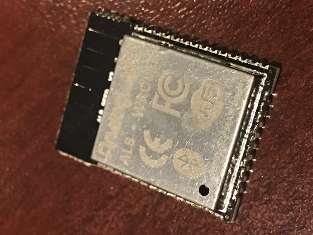
An update on SD card issues. We’ve (finally) narrowed down the problem. It seems our wiring is fine, pull-ups are fine, and software is as expected. No problem with interference, or power supply. The issue seems to be a conflict in the ESP IDF (probably bootloader, or ESP hardware) when using our external 16MB flash. Flash memory in the ESP32 is controlled over an SPI bus. We use the same SPI bus pins as the standard on-board flash, but a different CS (Chip Select) line (GPIO22 vs SD3 pin #19 for the standard 4MB flash chip). We burn fuses to tell the ESP32 to use our flash CS line (rather than the built-in one). That’s it. Nothing special, and no pin conflicts. We think some other conflict between the SD CARD and SPI hardware in the ESP-32 chip (perhaps requiring special handling in the bootloader / library code). Now, when OVMS is using this external flash, and accessing SD CARD, it becomes unreliable. It may seem fine, but read/write a lot and it fails. Replace the WROOM-32 module with one without efuses burnt (using internal 4MB flash), and the SD CARD goes back to working normally. I’ve finally (god, this has been frustrating) got someone at Espressif to recognise the problem and they are trying to re-create. The solution may be resolvable in bootloader code (best case), or may require a hardware fix. Whichever, we are close. While researching workarounds, and bearing in mind the latest ESP32 WROVER modules offering external PSRAM (SPI RAM; to expand RAM space in a similar way to external flash expands code space), I found a company called AnalogLamb <https://www.analoglamb.com/product/alb32-wrover-esp32-module-with-64mb-flash-and-32mb-psram/> These guys make a pin-compatible WROOM32 module including different size FLASH and PSRAM chips. We can get a module with 16MB flash and 4MB PSRAM - giving us the flash space we need, and another 4MB of heap space in RAM. It is not quite a drop-in replacement, as GPIO16+17 are used for the PSRAM (so we would have to move the GPIOs used for our modem), and the PSRAM requires the latest ESP IDF version (which brings other issues with it), but it seems to be a workable solution. I’ve gotten a hold of two sample modules (just arrived today) and will be trying them tonight. I’ll let you know how it works out. Regards, Mark.
On 7 Nov 2017, at 9:11 PM, Mark Webb-Johnson <mark@webb-johnson.net> wrote:
Edward, Steve: thanks for your feedback.
I made some progress. It turns out that the stuck-in-download-mode-after-flashing issue is caused by the SD CARD itself (not GPIO0 as I had thought). If I flash with the SD CARD inserted, I get that issue. If I remove the SD CARD, then reset, the module boots fine. I can then re-insert the SD CARD and everything is fine until next time I flash.
So, something in the SD CARD itself is pulling down GPIO2, after flashing. That is D0, and very bizarre.
However, I think that is a workable compromise; we can’t flash with an SD CARD inserted.
I guess I can play around with the pull-up resistor size on D0 to see if I can improve on this, but I’m willing to live with that compromise.
So, it is working now on breadboard in 1 line mode.
I’m now going to move on to trying to get it to work with our external SPI flash arrangement, and 1 line mode. I have a breadboard already setup for that - just some re-wiring to be done.
If that works, I’ll try 4 line mode.
Onwards…
Mark.
On 6 Nov 2017, at 1:27 PM, Mark Webb-Johnson <mark@webb-johnson.net <mailto:mark@webb-johnson.net>> wrote:
Some more notes on this:
Back to basics. I made a simple breadboard using standard Espressif code (attached) and a Geikcreit development board.
Wiring is GPIO14 -> CLK, GPIO15->CMD, CPIO2->D0, GPIO0->GPIO2 link, GND and 3.3V. 10K Pullups on CLK, CMD, D0 and D3. Software is set to 1bit SD mode.
If I plug-in USB power, start monitor terminal, all works perfectly:
I (276) example: Initializing SD card I (276) example: Using SDMMC peripheral Name: SC16G Type: SDHC/SDXC Speed: default speed Size: 15193MB CSD: ver=1, sector_size=512, capacity=31116288 read_bl_len=9 SCR: sd_spec=2, bus_width=5 I (356) example: Opening file I (366) example: File written I (376) example: Renaming file I (376) example: Reading file I (376) example: Read from file: 'Hello SC16G!' I (376) example: SD CARD test starts... I (386) example: SD CARD written 0/2048 I (526) example: SD CARD written 128/2048 I (676) example: SD CARD written 256/2048 I (816) example: SD CARD written 384/2048 I (956) example: SD CARD written 512/2048 I (1106) example: SD CARD written 640/2048 I (1246) example: SD CARD written 768/2048 I (1386) example: SD CARD written 896/2048 I (1526) example: SD CARD written 1024/2048 I (1676) example: SD CARD written 1152/2048 I (1816) example: SD CARD written 1280/2048 I (1966) example: SD CARD written 1408/2048 I (2106) example: SD CARD written 1536/2048 I (2246) example: SD CARD written 1664/2048 I (2396) example: SD CARD written 1792/2048 I (2546) example: SD CARD written 1920/2048 I (2686) example: Cleaning up I (2696) example: Card unmounted
In that case, GPIO0/GPIO2 has 2.567v. Pressing BOOT key brings GPIO0/GPIO2 to 0v, and back to 2.567v when release the button. During SDCARD test, GPIO0/GPIO2 is at around 0.682v.
With monitor connected, if I flash, GPIO0/GPIO2 is 0.323v. Screen says:
rst:0x1 (POWERON_RESET),boot:0x3 (DOWNLOAD_BOOT(UART0/UART1/SDIO_REI_REO_V2)) waiting for download
Pressing boot key goes to 0v, then releasing it goes back to 0.323v.
Pressing RESET key, no change. Stuck.
Disconnecting terminal monitor, no change. Stuck.
Reconnecting terminal monitor, no change. Stuck.
Removed link between GPIO0 and GPIO2. Now GPIO0 measures 3.3v and GPIO2 measures 0v.
Reconnection link between GPIO0 and GPIO2. Now GPIO0/GPIO2 measures 3.3v, boot ok, and SDCARD test runs ok.
So, it seems the transistor reset circuitry is not working correctly. I have tried asking on the esp32.com <http://esp32.com/> forums, but nobody answering.
Any ideas?
Regards, Mark.
Begin forwarded message:
From: Mark Webb-Johnson <mark@webb-johnson.net <mailto:mark@webb-johnson.net>> Subject: SD CARD Date: 26 October 2017 at 10:26:01 PM HKT
Any electronics guys out there can help out with SD CARD? It is frustrating as hell. The last part of the hardware puzzle. Once we solve this, we can hit the button to start making these. China and I have been struggling with this for the last month, with little progress.
We are just following the standard Espressif schematics for this. Here is Espressif’s master document on it:
https://github.com/espressif/esp-idf/tree/master/examples/storage/sd_card <https://github.com/espressif/esp-idf/tree/master/examples/storage/sd_card>
Our circuit has been built for 4 wire SD mode, using the standard pins and pullups (as documented by Espressif). Result is that it is unreliable. Fails to mount 90% of SD CARDS, and those that do mount fail and corrupt data when writing lots of data out.
The core problem (we think) is that the GPIO2 and GPIO12 pins used for SD CARD are also required to be at specific values during boot (to select different boot modes). Espressif suggest to work around this using the transistor logic they have for controlling boot mode pins using the USB-to-serial converter and DTR + RTS async control pins.
We want 4-wire, but let’s start with a simple 1-wire diagram on a breadboard (as per Espressif instructions):
ESP32 pin SD card pin SPI pin Notes GPIO14 (MTMS) CLK SCK 10k pullup in SD mode GPIO15 (MTDO) CMD MOSI 10k pullup, both in SD and SPI modes GPIO2 D0 MISO 10k pullup in SD mode, pull low to go into download mode (see note below!) GPIO4 D1 N/C not used in 1-line SD mode; 10k pullup in 4-line SD mode GPIO12 (MTDI) D2 N/C not used in 1-line SD mode; 10k pullup in 4-line SD mode (see note below!) GPIO13 (MTCK) D3 CS not used in 1-line SD mode, but card's D3 pin must have a 10k pullup N/C CD optional, not used in the example N/C WP optional, not used in the example
Also: Connect GPIO0 and GPIO2 using a jumper (so transistors drive GPIO2 and GPIO0 low when entering download mode (10K pullup otherwise) 3.3V connect to SDCARD GND connect to SDCARD
We have a variety of ESP32 development modules to try this with. Espressif said that the original DEVKIT C had a problem with the boot pin control lines and transistor logic (but never said what exactly that problem was).
With original (old) ESP32 DEVKIT C, I can’t get it to work reliably at all. Sometimes ok. Sometimes not. With OVMS test code (that writes a lot of data), it never works.
With our OVMS boards, all versions, I can’t get it to work reliably at all. Sometimes ok. Sometimes not. With OVMS test code (that writes a lot of data), it never works.
I don’t think it ever worked. Just before our test was so simple that it didn’t show the problem.
So, I just purchased one of these:
https://www.banggood.com/ESP32-Development-Board-WiFiBluetooth-Ultra-Low-Pow... <https://www.banggood.com/ESP32-Development-Board-WiFiBluetooth-Ultra-Low-Power-Consumption-Dual-Cores-ESP-32-ESP-32S-Board-p-1109512.html>
Geekcreit® ESP32 Development Board WiFi+Bluetooth Ultra Low Power Consumption Dual Cores ESP-32 ESP-32S Board
(Very similar to DEVKIT C, but more modern)
It works 100%. Although after flashing it cannot boot (waiting for download) - need to disconnect GPIO0 - GPIO2 link, reset, then reconnect GPIO0-GPIO2 link. Then perfect.
I think our problem is related to that transistor auto-flash reset circuitry. GPIO2 is the line for data transfer, so if problem will cause data corruption and unreliable (like we are seeing).
Espressif SD CARD notes here:
https://github.com/espressif/esp-idf/tree/master/examples/storage/sd_card <https://github.com/espressif/esp-idf/tree/master/examples/storage/sd_card>
Schematic for Geekcreit board is here:
https://www.dropbox.com/s/jefwxxtufgwg0ex/esp32_Schematic%20Prints.pdf?dl=0 <https://www.dropbox.com/s/jefwxxtufgwg0ex/esp32_Schematic%20Prints.pdf?dl=0>
<PastedGraphic-4.tiff>
Schematic for latest version of Espressif DEVKIT C board is here:
http://espressif.com/sites/default/files/documentation/esp32_hardware_design... <http://espressif.com/sites/default/files/documentation/esp32_hardware_design_guidelines_en.pdf>
<PastedGraphic-5.tiff>
The original DEVKIT C (v1) had 1K resistors on that circuit. This is the version I have.
The Geekcreit has 10K resistors on that circuit.
OVMS has 10K resistors on that circuit.
The latest DEVKIT C (v3) has 12K resistors on that circuit.
DEVKIT C v1 schematic is here: http://dl.espressif.com/dl/schematics/ESP32-DevKitJ-v1_sch.pdf <http://dl.espressif.com/dl/schematics/ESP32-DevKitJ-v1_sch.pdf> DEVKIT C v2 schematic is here: http://dl.espressif.com/dl/schematics/ESP-WROVER-KIT_SCH-2.pdf <http://dl.espressif.com/dl/schematics/ESP-WROVER-KIT_SCH-2.pdf>
The latest Espressif ROVER KIT development board schematic is here:
https://dl.espressif.com/dl/schematics/ESP-WROVER-KIT_SCH-3.pdf <https://dl.espressif.com/dl/schematics/ESP-WROVER-KIT_SCH-3.pdf>
<PastedGraphic-6.tiff>
<PastedGraphic-7.tiff>
Note that they are now using 100K resistors, and a separate transistor on IO0 (to allow it to be independently controlled after boot).
I am reasonably certain our SD CARD problem concerns the GPIO0-GPIO2 link.
Can you look at these, and see if you can find the difference? Apart from resistor sizes (which Espressif keep messing around with), I can’t see the practical difference.
Regards, Mark.
_______________________________________________ OvmsDev mailing list OvmsDev@lists.teslaclub.hk <mailto:OvmsDev@lists.teslaclub.hk> http://lists.teslaclub.hk/mailman/listinfo/ovmsdev
_______________________________________________ OvmsDev mailing list OvmsDev@lists.teslaclub.hk http://lists.teslaclub.hk/mailman/listinfo/ovmsdev
For those of you who’ve hit RAM limits, does this interest you? I (707) cpu_start: PSRAM mode: flash 40m sram 40m I (721) cpu_start: PSRAM initialized, cache is in even/odd (2-core) mode. I (3512) heap_alloc_caps: SPI SRAM memory test OK I (3513) heap_alloc_caps: Initializing. RAM available for dynamic allocation: I (3518) heap_alloc_caps: At 3F800000 len 00400000 (4096 KiB): SPIRAM I (3540) heap_alloc_caps: At 3FFAE2A0 len 00001D60 (7 KiB): DRAM I (3561) heap_alloc_caps: At 3FFB2378 len 0000DC88 (55 KiB): DRAM I (3582) heap_alloc_caps: At 3FFC0000 len 00008000 (32 KiB): DMAONLY I (3603) heap_alloc_caps: At 3FFC8000 len 00018000 (96 KiB): DRAM I (3624) heap_alloc_caps: At 3FFE0440 len 00003BC0 (14 KiB): D/IRAM I (3646) heap_alloc_caps: At 3FFE4350 len 0001BCB0 (111 KiB): D/IRAM I (3667) heap_alloc_caps: At 40089434 len 00016BCC (90 KiB): IRAM A normal ESP32 looks like this: I (777) heap_alloc_caps: Initializing. RAM available for dynamic allocation: I (799) heap_alloc_caps: At 3FFAE2A0 len 00001D60 (7 KiB): DRAM I (819) heap_alloc_caps: At 3FFB23E0 len 0002DC20 (183 KiB): DRAM I (840) heap_alloc_caps: At 3FFE0440 len 00003BC0 (14 KiB): D/IRAM I (861) heap_alloc_caps: At 3FFE4350 len 0001BCB0 (111 KiB): D/IRAM I (882) heap_alloc_caps: At 400874D0 len 00018B30 (98 KiB): IRAM Note: Some differences caused by ESP IDF v2.1 vs v3.x. There are still lots of restrictions (such as stacks only being in internal RAM unless the task doesn’t use wifi, bluetooth, rom routines, etc). But, for things like CAN bus RE, logging, etc, it could be pretty useful. Now, on to wire-up a SD CARD and see if it works. Should know in a few hours... Regards, Mark
On 23 Nov 2017, at 1:50 PM, Mark Webb-Johnson <mark@webb-johnson.net> wrote:
An update on SD card issues.
We’ve (finally) narrowed down the problem. It seems our wiring is fine, pull-ups are fine, and software is as expected. No problem with interference, or power supply.
The issue seems to be a conflict in the ESP IDF (probably bootloader, or ESP hardware) when using our external 16MB flash. Flash memory in the ESP32 is controlled over an SPI bus. We use the same SPI bus pins as the standard on-board flash, but a different CS (Chip Select) line (GPIO22 vs SD3 pin #19 for the standard 4MB flash chip). We burn fuses to tell the ESP32 to use our flash CS line (rather than the built-in one). That’s it. Nothing special, and no pin conflicts. We think some other conflict between the SD CARD and SPI hardware in the ESP-32 chip (perhaps requiring special handling in the bootloader / library code).
Now, when OVMS is using this external flash, and accessing SD CARD, it becomes unreliable. It may seem fine, but read/write a lot and it fails. Replace the WROOM-32 module with one without efuses burnt (using internal 4MB flash), and the SD CARD goes back to working normally.
I’ve finally (god, this has been frustrating) got someone at Espressif to recognise the problem and they are trying to re-create. The solution may be resolvable in bootloader code (best case), or may require a hardware fix. Whichever, we are close.
While researching workarounds, and bearing in mind the latest ESP32 WROVER modules offering external PSRAM (SPI RAM; to expand RAM space in a similar way to external flash expands code space), I found a company called AnalogLamb <https://www.analoglamb.com/product/alb32-wrover-esp32-module-with-64mb-flash-and-32mb-psram/> These guys make a pin-compatible WROOM32 module including different size FLASH and PSRAM chips. We can get a module with 16MB flash and 4MB PSRAM - giving us the flash space we need, and another 4MB of heap space in RAM. It is not quite a drop-in replacement, as GPIO16+17 are used for the PSRAM (so we would have to move the GPIOs used for our modem), and the PSRAM requires the latest ESP IDF version (which brings other issues with it), but it seems to be a workable solution. I’ve gotten a hold of two sample modules (just arrived today) and will be trying them tonight. I’ll let you know how it works out.
Regards, Mark.
<IMG_5655.jpeg>
On 7 Nov 2017, at 9:11 PM, Mark Webb-Johnson <mark@webb-johnson.net <mailto:mark@webb-johnson.net>> wrote:
Edward, Steve: thanks for your feedback.
I made some progress. It turns out that the stuck-in-download-mode-after-flashing issue is caused by the SD CARD itself (not GPIO0 as I had thought). If I flash with the SD CARD inserted, I get that issue. If I remove the SD CARD, then reset, the module boots fine. I can then re-insert the SD CARD and everything is fine until next time I flash.
So, something in the SD CARD itself is pulling down GPIO2, after flashing. That is D0, and very bizarre.
However, I think that is a workable compromise; we can’t flash with an SD CARD inserted.
I guess I can play around with the pull-up resistor size on D0 to see if I can improve on this, but I’m willing to live with that compromise.
So, it is working now on breadboard in 1 line mode.
I’m now going to move on to trying to get it to work with our external SPI flash arrangement, and 1 line mode. I have a breadboard already setup for that - just some re-wiring to be done.
If that works, I’ll try 4 line mode.
Onwards…
Mark.
On 6 Nov 2017, at 1:27 PM, Mark Webb-Johnson <mark@webb-johnson.net <mailto:mark@webb-johnson.net>> wrote:
Some more notes on this:
Back to basics. I made a simple breadboard using standard Espressif code (attached) and a Geikcreit development board.
Wiring is GPIO14 -> CLK, GPIO15->CMD, CPIO2->D0, GPIO0->GPIO2 link, GND and 3.3V. 10K Pullups on CLK, CMD, D0 and D3. Software is set to 1bit SD mode.
If I plug-in USB power, start monitor terminal, all works perfectly:
I (276) example: Initializing SD card I (276) example: Using SDMMC peripheral Name: SC16G Type: SDHC/SDXC Speed: default speed Size: 15193MB CSD: ver=1, sector_size=512, capacity=31116288 read_bl_len=9 SCR: sd_spec=2, bus_width=5 I (356) example: Opening file I (366) example: File written I (376) example: Renaming file I (376) example: Reading file I (376) example: Read from file: 'Hello SC16G!' I (376) example: SD CARD test starts... I (386) example: SD CARD written 0/2048 I (526) example: SD CARD written 128/2048 I (676) example: SD CARD written 256/2048 I (816) example: SD CARD written 384/2048 I (956) example: SD CARD written 512/2048 I (1106) example: SD CARD written 640/2048 I (1246) example: SD CARD written 768/2048 I (1386) example: SD CARD written 896/2048 I (1526) example: SD CARD written 1024/2048 I (1676) example: SD CARD written 1152/2048 I (1816) example: SD CARD written 1280/2048 I (1966) example: SD CARD written 1408/2048 I (2106) example: SD CARD written 1536/2048 I (2246) example: SD CARD written 1664/2048 I (2396) example: SD CARD written 1792/2048 I (2546) example: SD CARD written 1920/2048 I (2686) example: Cleaning up I (2696) example: Card unmounted
In that case, GPIO0/GPIO2 has 2.567v. Pressing BOOT key brings GPIO0/GPIO2 to 0v, and back to 2.567v when release the button. During SDCARD test, GPIO0/GPIO2 is at around 0.682v.
With monitor connected, if I flash, GPIO0/GPIO2 is 0.323v. Screen says:
rst:0x1 (POWERON_RESET),boot:0x3 (DOWNLOAD_BOOT(UART0/UART1/SDIO_REI_REO_V2)) waiting for download
Pressing boot key goes to 0v, then releasing it goes back to 0.323v.
Pressing RESET key, no change. Stuck.
Disconnecting terminal monitor, no change. Stuck.
Reconnecting terminal monitor, no change. Stuck.
Removed link between GPIO0 and GPIO2. Now GPIO0 measures 3.3v and GPIO2 measures 0v.
Reconnection link between GPIO0 and GPIO2. Now GPIO0/GPIO2 measures 3.3v, boot ok, and SDCARD test runs ok.
So, it seems the transistor reset circuitry is not working correctly. I have tried asking on the esp32.com <http://esp32.com/> forums, but nobody answering.
Any ideas?
Regards, Mark.
Begin forwarded message:
From: Mark Webb-Johnson <mark@webb-johnson.net <mailto:mark@webb-johnson.net>> Subject: SD CARD Date: 26 October 2017 at 10:26:01 PM HKT
Any electronics guys out there can help out with SD CARD? It is frustrating as hell. The last part of the hardware puzzle. Once we solve this, we can hit the button to start making these. China and I have been struggling with this for the last month, with little progress.
We are just following the standard Espressif schematics for this. Here is Espressif’s master document on it:
https://github.com/espressif/esp-idf/tree/master/examples/storage/sd_card <https://github.com/espressif/esp-idf/tree/master/examples/storage/sd_card>
Our circuit has been built for 4 wire SD mode, using the standard pins and pullups (as documented by Espressif). Result is that it is unreliable. Fails to mount 90% of SD CARDS, and those that do mount fail and corrupt data when writing lots of data out.
The core problem (we think) is that the GPIO2 and GPIO12 pins used for SD CARD are also required to be at specific values during boot (to select different boot modes). Espressif suggest to work around this using the transistor logic they have for controlling boot mode pins using the USB-to-serial converter and DTR + RTS async control pins.
We want 4-wire, but let’s start with a simple 1-wire diagram on a breadboard (as per Espressif instructions):
ESP32 pin SD card pin SPI pin Notes GPIO14 (MTMS) CLK SCK 10k pullup in SD mode GPIO15 (MTDO) CMD MOSI 10k pullup, both in SD and SPI modes GPIO2 D0 MISO 10k pullup in SD mode, pull low to go into download mode (see note below!) GPIO4 D1 N/C not used in 1-line SD mode; 10k pullup in 4-line SD mode GPIO12 (MTDI) D2 N/C not used in 1-line SD mode; 10k pullup in 4-line SD mode (see note below!) GPIO13 (MTCK) D3 CS not used in 1-line SD mode, but card's D3 pin must have a 10k pullup N/C CD optional, not used in the example N/C WP optional, not used in the example
Also: Connect GPIO0 and GPIO2 using a jumper (so transistors drive GPIO2 and GPIO0 low when entering download mode (10K pullup otherwise) 3.3V connect to SDCARD GND connect to SDCARD
We have a variety of ESP32 development modules to try this with. Espressif said that the original DEVKIT C had a problem with the boot pin control lines and transistor logic (but never said what exactly that problem was).
With original (old) ESP32 DEVKIT C, I can’t get it to work reliably at all. Sometimes ok. Sometimes not. With OVMS test code (that writes a lot of data), it never works.
With our OVMS boards, all versions, I can’t get it to work reliably at all. Sometimes ok. Sometimes not. With OVMS test code (that writes a lot of data), it never works.
I don’t think it ever worked. Just before our test was so simple that it didn’t show the problem.
So, I just purchased one of these:
https://www.banggood.com/ESP32-Development-Board-WiFiBluetooth-Ultra-Low-Pow... <https://www.banggood.com/ESP32-Development-Board-WiFiBluetooth-Ultra-Low-Power-Consumption-Dual-Cores-ESP-32-ESP-32S-Board-p-1109512.html>
Geekcreit® ESP32 Development Board WiFi+Bluetooth Ultra Low Power Consumption Dual Cores ESP-32 ESP-32S Board
(Very similar to DEVKIT C, but more modern)
It works 100%. Although after flashing it cannot boot (waiting for download) - need to disconnect GPIO0 - GPIO2 link, reset, then reconnect GPIO0-GPIO2 link. Then perfect.
I think our problem is related to that transistor auto-flash reset circuitry. GPIO2 is the line for data transfer, so if problem will cause data corruption and unreliable (like we are seeing).
Espressif SD CARD notes here:
https://github.com/espressif/esp-idf/tree/master/examples/storage/sd_card <https://github.com/espressif/esp-idf/tree/master/examples/storage/sd_card>
Schematic for Geekcreit board is here:
https://www.dropbox.com/s/jefwxxtufgwg0ex/esp32_Schematic%20Prints.pdf?dl=0 <https://www.dropbox.com/s/jefwxxtufgwg0ex/esp32_Schematic%20Prints.pdf?dl=0>
<PastedGraphic-4.tiff>
Schematic for latest version of Espressif DEVKIT C board is here:
http://espressif.com/sites/default/files/documentation/esp32_hardware_design... <http://espressif.com/sites/default/files/documentation/esp32_hardware_design_guidelines_en.pdf>
<PastedGraphic-5.tiff>
The original DEVKIT C (v1) had 1K resistors on that circuit. This is the version I have.
The Geekcreit has 10K resistors on that circuit.
OVMS has 10K resistors on that circuit.
The latest DEVKIT C (v3) has 12K resistors on that circuit.
DEVKIT C v1 schematic is here: http://dl.espressif.com/dl/schematics/ESP32-DevKitJ-v1_sch.pdf <http://dl.espressif.com/dl/schematics/ESP32-DevKitJ-v1_sch.pdf> DEVKIT C v2 schematic is here: http://dl.espressif.com/dl/schematics/ESP-WROVER-KIT_SCH-2.pdf <http://dl.espressif.com/dl/schematics/ESP-WROVER-KIT_SCH-2.pdf>
The latest Espressif ROVER KIT development board schematic is here:
https://dl.espressif.com/dl/schematics/ESP-WROVER-KIT_SCH-3.pdf <https://dl.espressif.com/dl/schematics/ESP-WROVER-KIT_SCH-3.pdf>
<PastedGraphic-6.tiff>
<PastedGraphic-7.tiff>
Note that they are now using 100K resistors, and a separate transistor on IO0 (to allow it to be independently controlled after boot).
I am reasonably certain our SD CARD problem concerns the GPIO0-GPIO2 link.
Can you look at these, and see if you can find the difference? Apart from resistor sizes (which Espressif keep messing around with), I can’t see the practical difference.
Regards, Mark.
_______________________________________________ OvmsDev mailing list OvmsDev@lists.teslaclub.hk <mailto:OvmsDev@lists.teslaclub.hk> http://lists.teslaclub.hk/mailman/listinfo/ovmsdev <http://lists.teslaclub.hk/mailman/listinfo/ovmsdev>
_______________________________________________ OvmsDev mailing list OvmsDev@lists.teslaclub.hk <mailto:OvmsDev@lists.teslaclub.hk> http://lists.teslaclub.hk/mailman/listinfo/ovmsdev

Mark, I presume the SPIRAM is slower. How much? -- Steve On Thu, 23 Nov 2017, Mark Webb-Johnson wrote:
For those of you who’ve hit RAM limits, does this interest you?
I (707) cpu_start: PSRAM mode: flash 40m sram 40m I (721) cpu_start: PSRAM initialized, cache is in even/odd (2-core) mode.
I (3512) heap_alloc_caps: SPI SRAM memory test OK I (3513) heap_alloc_caps: Initializing. RAM available for dynamic allocation: I (3518) heap_alloc_caps: At 3F800000 len 00400000 (4096 KiB): SPIRAM I (3540) heap_alloc_caps: At 3FFAE2A0 len 00001D60 (7 KiB): DRAM I (3561) heap_alloc_caps: At 3FFB2378 len 0000DC88 (55 KiB): DRAM I (3582) heap_alloc_caps: At 3FFC0000 len 00008000 (32 KiB): DMAONLY I (3603) heap_alloc_caps: At 3FFC8000 len 00018000 (96 KiB): DRAM I (3624) heap_alloc_caps: At 3FFE0440 len 00003BC0 (14 KiB): D/IRAM I (3646) heap_alloc_caps: At 3FFE4350 len 0001BCB0 (111 KiB): D/IRAM I (3667) heap_alloc_caps: At 40089434 len 00016BCC (90 KiB): IRAM
A normal ESP32 looks like this:
I (777) heap_alloc_caps: Initializing. RAM available for dynamic allocation: I (799) heap_alloc_caps: At 3FFAE2A0 len 00001D60 (7 KiB): DRAM I (819) heap_alloc_caps: At 3FFB23E0 len 0002DC20 (183 KiB): DRAM I (840) heap_alloc_caps: At 3FFE0440 len 00003BC0 (14 KiB): D/IRAM I (861) heap_alloc_caps: At 3FFE4350 len 0001BCB0 (111 KiB): D/IRAM I (882) heap_alloc_caps: At 400874D0 len 00018B30 (98 KiB): IRAM
Note: Some differences caused by ESP IDF v2.1 vs v3.x.
There are still lots of restrictions (such as stacks only being in internal RAM unless the task doesn’t use wifi, bluetooth, rom routines, etc). But, for things like CAN bus RE, logging, etc, it could be pretty useful. Now, on to wire-up a SD CARD and see if it works. Should know in a few hours...
Regards, Mark
On 23 Nov 2017, at 1:50 PM, Mark Webb-Johnson <mark@webb-johnson.net> wrote:
An update on SD card issues.
We’ve (finally) narrowed down the problem. It seems our wiring is fine, pull-ups are fine, and software is as expected. No problem with interference, or power supply.
The issue seems to be a conflict in the ESP IDF (probably bootloader, or ESP hardware) when using our external 16MB flash. Flash memory in the ESP32 is controlled over an SPI bus. We use the same SPI bus pins as the standard on-board flash, but a different CS (Chip Select) line (GPIO22 vs SD3 pin #19 for the standard 4MB flash chip). We burn fuses to tell the ESP32 to use our flash CS line (rather than the built-in one). That’s it. Nothing special, and no pin conflicts. We think some other conflict between the SD CARD and SPI hardware in the ESP-32 chip (perhaps requiring special handling in the bootloader / library code).
Now, when OVMS is using this external flash, and accessing SD CARD, it becomes unreliable. It may seem fine, but read/write a lot and it fails. Replace the WROOM-32 module with one without efuses burnt (using internal 4MB flash), and the SD CARD goes back to working normally.
I’ve finally (god, this has been frustrating) got someone at Espressif to recognise the problem and they are trying to re-create. The solution may be resolvable in bootloader code (best case), or may require a hardware fix. Whichever, we are close.
While researching workarounds, and bearing in mind the latest ESP32 WROVER modules offering external PSRAM (SPI RAM; to expand RAM space in a similar way to external flash expands code space), I found a company called AnalogLamb <https://www.analoglamb.com/product/alb32-wrover-esp32-module-with-64mb-flash-and-32mb-psram/> These guys make a pin-compatible WROOM32 module including different size FLASH and PSRAM chips. We can get a module with 16MB flash and 4MB PSRAM - giving us the flash space we need, and another 4MB of heap space in RAM. It is not quite a drop-in replacement, as GPIO16+17 are used for the PSRAM (so we would have to move the GPIOs used for our modem), and the PSRAM requires the latest ESP IDF version (which brings other issues with it), but it seems to be a workable solution. I’ve gotten a hold of two sample modules (just arrived today) and will be trying them tonight. I’ll let you know how it works out.
Regards, Mark.
<IMG_5655.jpeg>
On 7 Nov 2017, at 9:11 PM, Mark Webb-Johnson <mark@webb-johnson.net <mailto:mark@webb-johnson.net>> wrote:
Edward, Steve: thanks for your feedback.
I made some progress. It turns out that the stuck-in-download-mode-after-flashing issue is caused by the SD CARD itself (not GPIO0 as I had thought). If I flash with the SD CARD inserted, I get that issue. If I remove the SD CARD, then reset, the module boots fine. I can then re-insert the SD CARD and everything is fine until next time I flash.
So, something in the SD CARD itself is pulling down GPIO2, after flashing. That is D0, and very bizarre.
However, I think that is a workable compromise; we can’t flash with an SD CARD inserted.
I guess I can play around with the pull-up resistor size on D0 to see if I can improve on this, but I’m willing to live with that compromise.
So, it is working now on breadboard in 1 line mode.
I’m now going to move on to trying to get it to work with our external SPI flash arrangement, and 1 line mode. I have a breadboard already setup for that - just some re-wiring to be done.
If that works, I’ll try 4 line mode.
Onwards…
Mark.
On 6 Nov 2017, at 1:27 PM, Mark Webb-Johnson <mark@webb-johnson.net <mailto:mark@webb-johnson.net>> wrote:
Some more notes on this:
Back to basics. I made a simple breadboard using standard Espressif code (attached) and a Geikcreit development board.
Wiring is GPIO14 -> CLK, GPIO15->CMD, CPIO2->D0, GPIO0->GPIO2 link, GND and 3.3V. 10K Pullups on CLK, CMD, D0 and D3. Software is set to 1bit SD mode.
If I plug-in USB power, start monitor terminal, all works perfectly:
I (276) example: Initializing SD card I (276) example: Using SDMMC peripheral Name: SC16G Type: SDHC/SDXC Speed: default speed Size: 15193MB CSD: ver=1, sector_size=512, capacity=31116288 read_bl_len=9 SCR: sd_spec=2, bus_width=5 I (356) example: Opening file I (366) example: File written I (376) example: Renaming file I (376) example: Reading file I (376) example: Read from file: 'Hello SC16G!' I (376) example: SD CARD test starts... I (386) example: SD CARD written 0/2048 I (526) example: SD CARD written 128/2048 I (676) example: SD CARD written 256/2048 I (816) example: SD CARD written 384/2048 I (956) example: SD CARD written 512/2048 I (1106) example: SD CARD written 640/2048 I (1246) example: SD CARD written 768/2048 I (1386) example: SD CARD written 896/2048 I (1526) example: SD CARD written 1024/2048 I (1676) example: SD CARD written 1152/2048 I (1816) example: SD CARD written 1280/2048 I (1966) example: SD CARD written 1408/2048 I (2106) example: SD CARD written 1536/2048 I (2246) example: SD CARD written 1664/2048 I (2396) example: SD CARD written 1792/2048 I (2546) example: SD CARD written 1920/2048 I (2686) example: Cleaning up I (2696) example: Card unmounted
In that case, GPIO0/GPIO2 has 2.567v. Pressing BOOT key brings GPIO0/GPIO2 to 0v, and back to 2.567v when release the button. During SDCARD test, GPIO0/GPIO2 is at around 0.682v.
With monitor connected, if I flash, GPIO0/GPIO2 is 0.323v. Screen says:
rst:0x1 (POWERON_RESET),boot:0x3 (DOWNLOAD_BOOT(UART0/UART1/SDIO_REI_REO_V2)) waiting for download
Pressing boot key goes to 0v, then releasing it goes back to 0.323v.
Pressing RESET key, no change. Stuck.
Disconnecting terminal monitor, no change. Stuck.
Reconnecting terminal monitor, no change. Stuck.
Removed link between GPIO0 and GPIO2. Now GPIO0 measures 3.3v and GPIO2 measures 0v.
Reconnection link between GPIO0 and GPIO2. Now GPIO0/GPIO2 measures 3.3v, boot ok, and SDCARD test runs ok.
So, it seems the transistor reset circuitry is not working correctly. I have tried asking on the esp32.com <http://esp32.com/> forums, but nobody answering.
Any ideas?
Regards, Mark.
Begin forwarded message:
From: Mark Webb-Johnson <mark@webb-johnson.net <mailto:mark@webb-johnson.net>> Subject: SD CARD Date: 26 October 2017 at 10:26:01 PM HKT
Any electronics guys out there can help out with SD CARD? It is frustrating as hell. The last part of the hardware puzzle. Once we solve this, we can hit the button to start making these. China and I have been struggling with this for the last month, with little progress.
We are just following the standard Espressif schematics for this. Here is Espressif’s master document on it:
https://github.com/espressif/esp-idf/tree/master/examples/storage/sd_card <https://github.com/espressif/esp-idf/tree/master/examples/storage/sd_card>
Our circuit has been built for 4 wire SD mode, using the standard pins and pullups (as documented by Espressif). Result is that it is unreliable. Fails to mount 90% of SD CARDS, and those that do mount fail and corrupt data when writing lots of data out.
The core problem (we think) is that the GPIO2 and GPIO12 pins used for SD CARD are also required to be at specific values during boot (to select different boot modes). Espressif suggest to work around this using the transistor logic they have for controlling boot mode pins using the USB-to-serial converter and DTR + RTS async control pins.
We want 4-wire, but let’s start with a simple 1-wire diagram on a breadboard (as per Espressif instructions):
ESP32 pin SD card pin SPI pin Notes GPIO14 (MTMS) CLK SCK 10k pullup in SD mode GPIO15 (MTDO) CMD MOSI 10k pullup, both in SD and SPI modes GPIO2 D0 MISO 10k pullup in SD mode, pull low to go into download mode (see note below!) GPIO4 D1 N/C not used in 1-line SD mode; 10k pullup in 4-line SD mode GPIO12 (MTDI) D2 N/C not used in 1-line SD mode; 10k pullup in 4-line SD mode (see note below!) GPIO13 (MTCK) D3 CS not used in 1-line SD mode, but card's D3 pin must have a 10k pullup N/C CD optional, not used in the example N/C WP optional, not used in the example
Also: Connect GPIO0 and GPIO2 using a jumper (so transistors drive GPIO2 and GPIO0 low when entering download mode (10K pullup otherwise) 3.3V connect to SDCARD GND connect to SDCARD
We have a variety of ESP32 development modules to try this with. Espressif said that the original DEVKIT C had a problem with the boot pin control lines and transistor logic (but never said what exactly that problem was).
With original (old) ESP32 DEVKIT C, I can’t get it to work reliably at all. Sometimes ok. Sometimes not. With OVMS test code (that writes a lot of data), it never works.
With our OVMS boards, all versions, I can’t get it to work reliably at all. Sometimes ok. Sometimes not. With OVMS test code (that writes a lot of data), it never works.
I don’t think it ever worked. Just before our test was so simple that it didn’t show the problem.
So, I just purchased one of these:
https://www.banggood.com/ESP32-Development-Board-WiFiBluetooth-Ultra-Low-Pow... <https://www.banggood.com/ESP32-Development-Board-WiFiBluetooth-Ultra-Low-Power-Consumption-Dual-Cores-ESP-32-ESP-32S-Board-p-1109512.html>
Geekcreit® ESP32 Development Board WiFi+Bluetooth Ultra Low Power Consumption Dual Cores ESP-32 ESP-32S Board
(Very similar to DEVKIT C, but more modern)
It works 100%. Although after flashing it cannot boot (waiting for download) - need to disconnect GPIO0 - GPIO2 link, reset, then reconnect GPIO0-GPIO2 link. Then perfect.
I think our problem is related to that transistor auto-flash reset circuitry. GPIO2 is the line for data transfer, so if problem will cause data corruption and unreliable (like we are seeing).
Espressif SD CARD notes here:
https://github.com/espressif/esp-idf/tree/master/examples/storage/sd_card <https://github.com/espressif/esp-idf/tree/master/examples/storage/sd_card>
Schematic for Geekcreit board is here:
https://www.dropbox.com/s/jefwxxtufgwg0ex/esp32_Schematic%20Prints.pdf?dl=0 <https://www.dropbox.com/s/jefwxxtufgwg0ex/esp32_Schematic%20Prints.pdf?dl=0>
<PastedGraphic-4.tiff>
Schematic for latest version of Espressif DEVKIT C board is here:
http://espressif.com/sites/default/files/documentation/esp32_hardware_design... <http://espressif.com/sites/default/files/documentation/esp32_hardware_design_guidelines_en.pdf>
<PastedGraphic-5.tiff>
The original DEVKIT C (v1) had 1K resistors on that circuit. This is the version I have.
The Geekcreit has 10K resistors on that circuit.
OVMS has 10K resistors on that circuit.
The latest DEVKIT C (v3) has 12K resistors on that circuit.
DEVKIT C v1 schematic is here: http://dl.espressif.com/dl/schematics/ESP32-DevKitJ-v1_sch.pdf <http://dl.espressif.com/dl/schematics/ESP32-DevKitJ-v1_sch.pdf> DEVKIT C v2 schematic is here: http://dl.espressif.com/dl/schematics/ESP-WROVER-KIT_SCH-2.pdf <http://dl.espressif.com/dl/schematics/ESP-WROVER-KIT_SCH-2.pdf>
The latest Espressif ROVER KIT development board schematic is here:
https://dl.espressif.com/dl/schematics/ESP-WROVER-KIT_SCH-3.pdf <https://dl.espressif.com/dl/schematics/ESP-WROVER-KIT_SCH-3.pdf>
<PastedGraphic-6.tiff>
<PastedGraphic-7.tiff>
Note that they are now using 100K resistors, and a separate transistor on IO0 (to allow it to be independently controlled after boot).
I am reasonably certain our SD CARD problem concerns the GPIO0-GPIO2 link.
Can you look at these, and see if you can find the difference? Apart from resistor sizes (which Espressif keep messing around with), I can’t see the practical difference.
Regards, Mark.
_______________________________________________ OvmsDev mailing list OvmsDev@lists.teslaclub.hk <mailto:OvmsDev@lists.teslaclub.hk> http://lists.teslaclub.hk/mailman/listinfo/ovmsdev <http://lists.teslaclub.hk/mailman/listinfo/ovmsdev>
_______________________________________________ OvmsDev mailing list OvmsDev@lists.teslaclub.hk <mailto:OvmsDev@lists.teslaclub.hk> http://lists.teslaclub.hk/mailman/listinfo/ovmsdev
Not sure about speed of the chip itself. Communications bus is the same as the flash memory (40Mhz), and caching arrangement the same. I think speed should be comparable to flash used for program storage. But really depends on cachability. Regards, Mark
On 25 Nov 2017, at 2:47 PM, Stephen Casner <casner@acm.org> wrote:
Mark,
I presume the SPIRAM is slower. How much?
-- Steve
On Thu, 23 Nov 2017, Mark Webb-Johnson wrote:
For those of you who’ve hit RAM limits, does this interest you?
I (707) cpu_start: PSRAM mode: flash 40m sram 40m I (721) cpu_start: PSRAM initialized, cache is in even/odd (2-core) mode.
I (3512) heap_alloc_caps: SPI SRAM memory test OK I (3513) heap_alloc_caps: Initializing. RAM available for dynamic allocation: I (3518) heap_alloc_caps: At 3F800000 len 00400000 (4096 KiB): SPIRAM I (3540) heap_alloc_caps: At 3FFAE2A0 len 00001D60 (7 KiB): DRAM I (3561) heap_alloc_caps: At 3FFB2378 len 0000DC88 (55 KiB): DRAM I (3582) heap_alloc_caps: At 3FFC0000 len 00008000 (32 KiB): DMAONLY I (3603) heap_alloc_caps: At 3FFC8000 len 00018000 (96 KiB): DRAM I (3624) heap_alloc_caps: At 3FFE0440 len 00003BC0 (14 KiB): D/IRAM I (3646) heap_alloc_caps: At 3FFE4350 len 0001BCB0 (111 KiB): D/IRAM I (3667) heap_alloc_caps: At 40089434 len 00016BCC (90 KiB): IRAM
A normal ESP32 looks like this:
I (777) heap_alloc_caps: Initializing. RAM available for dynamic allocation: I (799) heap_alloc_caps: At 3FFAE2A0 len 00001D60 (7 KiB): DRAM I (819) heap_alloc_caps: At 3FFB23E0 len 0002DC20 (183 KiB): DRAM I (840) heap_alloc_caps: At 3FFE0440 len 00003BC0 (14 KiB): D/IRAM I (861) heap_alloc_caps: At 3FFE4350 len 0001BCB0 (111 KiB): D/IRAM I (882) heap_alloc_caps: At 400874D0 len 00018B30 (98 KiB): IRAM
Note: Some differences caused by ESP IDF v2.1 vs v3.x.
There are still lots of restrictions (such as stacks only being in internal RAM unless the task doesn’t use wifi, bluetooth, rom routines, etc). But, for things like CAN bus RE, logging, etc, it could be pretty useful. Now, on to wire-up a SD CARD and see if it works. Should know in a few hours...
Regards, Mark
On 23 Nov 2017, at 1:50 PM, Mark Webb-Johnson <mark@webb-johnson.net> wrote:
An update on SD card issues.
We’ve (finally) narrowed down the problem. It seems our wiring is fine, pull-ups are fine, and software is as expected. No problem with interference, or power supply.
The issue seems to be a conflict in the ESP IDF (probably bootloader, or ESP hardware) when using our external 16MB flash. Flash memory in the ESP32 is controlled over an SPI bus. We use the same SPI bus pins as the standard on-board flash, but a different CS (Chip Select) line (GPIO22 vs SD3 pin #19 for the standard 4MB flash chip). We burn fuses to tell the ESP32 to use our flash CS line (rather than the built-in one). That’s it. Nothing special, and no pin conflicts. We think some other conflict between the SD CARD and SPI hardware in the ESP-32 chip (perhaps requiring special handling in the bootloader / library code).
Now, when OVMS is using this external flash, and accessing SD CARD, it becomes unreliable. It may seem fine, but read/write a lot and it fails. Replace the WROOM-32 module with one without efuses burnt (using internal 4MB flash), and the SD CARD goes back to working normally.
I’ve finally (god, this has been frustrating) got someone at Espressif to recognise the problem and they are trying to re-create. The solution may be resolvable in bootloader code (best case), or may require a hardware fix. Whichever, we are close.
While researching workarounds, and bearing in mind the latest ESP32 WROVER modules offering external PSRAM (SPI RAM; to expand RAM space in a similar way to external flash expands code space), I found a company called AnalogLamb <https://www.analoglamb.com/product/alb32-wrover-esp32-module-with-64mb-flash-and-32mb-psram/> These guys make a pin-compatible WROOM32 module including different size FLASH and PSRAM chips. We can get a module with 16MB flash and 4MB PSRAM - giving us the flash space we need, and another 4MB of heap space in RAM. It is not quite a drop-in replacement, as GPIO16+17 are used for the PSRAM (so we would have to move the GPIOs used for our modem), and the PSRAM requires the latest ESP IDF version (which brings other issues with it), but it seems to be a workable solution. I’ve gotten a hold of two sample modules (just arrived today) and will be trying them tonight. I’ll let you know how it works out.
Regards, Mark.
<IMG_5655.jpeg>
On 7 Nov 2017, at 9:11 PM, Mark Webb-Johnson <mark@webb-johnson.net <mailto:mark@webb-johnson.net>> wrote:
Edward, Steve: thanks for your feedback.
I made some progress. It turns out that the stuck-in-download-mode-after-flashing issue is caused by the SD CARD itself (not GPIO0 as I had thought). If I flash with the SD CARD inserted, I get that issue. If I remove the SD CARD, then reset, the module boots fine. I can then re-insert the SD CARD and everything is fine until next time I flash.
So, something in the SD CARD itself is pulling down GPIO2, after flashing. That is D0, and very bizarre.
However, I think that is a workable compromise; we can’t flash with an SD CARD inserted.
I guess I can play around with the pull-up resistor size on D0 to see if I can improve on this, but I’m willing to live with that compromise.
So, it is working now on breadboard in 1 line mode.
I’m now going to move on to trying to get it to work with our external SPI flash arrangement, and 1 line mode. I have a breadboard already setup for that - just some re-wiring to be done.
If that works, I’ll try 4 line mode.
Onwards…
Mark.
On 6 Nov 2017, at 1:27 PM, Mark Webb-Johnson <mark@webb-johnson.net <mailto:mark@webb-johnson.net>> wrote:
Some more notes on this:
Back to basics. I made a simple breadboard using standard Espressif code (attached) and a Geikcreit development board.
Wiring is GPIO14 -> CLK, GPIO15->CMD, CPIO2->D0, GPIO0->GPIO2 link, GND and 3.3V. 10K Pullups on CLK, CMD, D0 and D3. Software is set to 1bit SD mode.
If I plug-in USB power, start monitor terminal, all works perfectly:
I (276) example: Initializing SD card I (276) example: Using SDMMC peripheral Name: SC16G Type: SDHC/SDXC Speed: default speed Size: 15193MB CSD: ver=1, sector_size=512, capacity=31116288 read_bl_len=9 SCR: sd_spec=2, bus_width=5 I (356) example: Opening file I (366) example: File written I (376) example: Renaming file I (376) example: Reading file I (376) example: Read from file: 'Hello SC16G!' I (376) example: SD CARD test starts... I (386) example: SD CARD written 0/2048 I (526) example: SD CARD written 128/2048 I (676) example: SD CARD written 256/2048 I (816) example: SD CARD written 384/2048 I (956) example: SD CARD written 512/2048 I (1106) example: SD CARD written 640/2048 I (1246) example: SD CARD written 768/2048 I (1386) example: SD CARD written 896/2048 I (1526) example: SD CARD written 1024/2048 I (1676) example: SD CARD written 1152/2048 I (1816) example: SD CARD written 1280/2048 I (1966) example: SD CARD written 1408/2048 I (2106) example: SD CARD written 1536/2048 I (2246) example: SD CARD written 1664/2048 I (2396) example: SD CARD written 1792/2048 I (2546) example: SD CARD written 1920/2048 I (2686) example: Cleaning up I (2696) example: Card unmounted
In that case, GPIO0/GPIO2 has 2.567v. Pressing BOOT key brings GPIO0/GPIO2 to 0v, and back to 2.567v when release the button. During SDCARD test, GPIO0/GPIO2 is at around 0.682v.
With monitor connected, if I flash, GPIO0/GPIO2 is 0.323v. Screen says:
rst:0x1 (POWERON_RESET),boot:0x3 (DOWNLOAD_BOOT(UART0/UART1/SDIO_REI_REO_V2)) waiting for download
Pressing boot key goes to 0v, then releasing it goes back to 0.323v.
Pressing RESET key, no change. Stuck.
Disconnecting terminal monitor, no change. Stuck.
Reconnecting terminal monitor, no change. Stuck.
Removed link between GPIO0 and GPIO2. Now GPIO0 measures 3.3v and GPIO2 measures 0v.
Reconnection link between GPIO0 and GPIO2. Now GPIO0/GPIO2 measures 3.3v, boot ok, and SDCARD test runs ok.
So, it seems the transistor reset circuitry is not working correctly. I have tried asking on the esp32.com <http://esp32.com/> forums, but nobody answering.
Any ideas?
Regards, Mark.
Begin forwarded message:
From: Mark Webb-Johnson <mark@webb-johnson.net <mailto:mark@webb-johnson.net>> Subject: SD CARD Date: 26 October 2017 at 10:26:01 PM HKT
Any electronics guys out there can help out with SD CARD? It is frustrating as hell. The last part of the hardware puzzle. Once we solve this, we can hit the button to start making these. China and I have been struggling with this for the last month, with little progress.
We are just following the standard Espressif schematics for this. Here is Espressif’s master document on it:
https://github.com/espressif/esp-idf/tree/master/examples/storage/sd_card <https://github.com/espressif/esp-idf/tree/master/examples/storage/sd_card>
Our circuit has been built for 4 wire SD mode, using the standard pins and pullups (as documented by Espressif). Result is that it is unreliable. Fails to mount 90% of SD CARDS, and those that do mount fail and corrupt data when writing lots of data out.
The core problem (we think) is that the GPIO2 and GPIO12 pins used for SD CARD are also required to be at specific values during boot (to select different boot modes). Espressif suggest to work around this using the transistor logic they have for controlling boot mode pins using the USB-to-serial converter and DTR + RTS async control pins.
We want 4-wire, but let’s start with a simple 1-wire diagram on a breadboard (as per Espressif instructions):
ESP32 pin SD card pin SPI pin Notes GPIO14 (MTMS) CLK SCK 10k pullup in SD mode GPIO15 (MTDO) CMD MOSI 10k pullup, both in SD and SPI modes GPIO2 D0 MISO 10k pullup in SD mode, pull low to go into download mode (see note below!) GPIO4 D1 N/C not used in 1-line SD mode; 10k pullup in 4-line SD mode GPIO12 (MTDI) D2 N/C not used in 1-line SD mode; 10k pullup in 4-line SD mode (see note below!) GPIO13 (MTCK) D3 CS not used in 1-line SD mode, but card's D3 pin must have a 10k pullup N/C CD optional, not used in the example N/C WP optional, not used in the example
Also: Connect GPIO0 and GPIO2 using a jumper (so transistors drive GPIO2 and GPIO0 low when entering download mode (10K pullup otherwise) 3.3V connect to SDCARD GND connect to SDCARD
We have a variety of ESP32 development modules to try this with. Espressif said that the original DEVKIT C had a problem with the boot pin control lines and transistor logic (but never said what exactly that problem was).
With original (old) ESP32 DEVKIT C, I can’t get it to work reliably at all. Sometimes ok. Sometimes not. With OVMS test code (that writes a lot of data), it never works.
With our OVMS boards, all versions, I can’t get it to work reliably at all. Sometimes ok. Sometimes not. With OVMS test code (that writes a lot of data), it never works.
I don’t think it ever worked. Just before our test was so simple that it didn’t show the problem.
So, I just purchased one of these:
https://www.banggood.com/ESP32-Development-Board-WiFiBluetooth-Ultra-Low-Pow... <https://www.banggood.com/ESP32-Development-Board-WiFiBluetooth-Ultra-Low-Power-Consumption-Dual-Cores-ESP-32-ESP-32S-Board-p-1109512.html>
Geekcreit® ESP32 Development Board WiFi+Bluetooth Ultra Low Power Consumption Dual Cores ESP-32 ESP-32S Board
(Very similar to DEVKIT C, but more modern)
It works 100%. Although after flashing it cannot boot (waiting for download) - need to disconnect GPIO0 - GPIO2 link, reset, then reconnect GPIO0-GPIO2 link. Then perfect.
I think our problem is related to that transistor auto-flash reset circuitry. GPIO2 is the line for data transfer, so if problem will cause data corruption and unreliable (like we are seeing).
Espressif SD CARD notes here:
https://github.com/espressif/esp-idf/tree/master/examples/storage/sd_card <https://github.com/espressif/esp-idf/tree/master/examples/storage/sd_card>
Schematic for Geekcreit board is here:
https://www.dropbox.com/s/jefwxxtufgwg0ex/esp32_Schematic%20Prints.pdf?dl=0 <https://www.dropbox.com/s/jefwxxtufgwg0ex/esp32_Schematic%20Prints.pdf?dl=0>
<PastedGraphic-4.tiff>
Schematic for latest version of Espressif DEVKIT C board is here:
http://espressif.com/sites/default/files/documentation/esp32_hardware_design... <http://espressif.com/sites/default/files/documentation/esp32_hardware_design_guidelines_en.pdf>
<PastedGraphic-5.tiff>
The original DEVKIT C (v1) had 1K resistors on that circuit. This is the version I have.
The Geekcreit has 10K resistors on that circuit.
OVMS has 10K resistors on that circuit.
The latest DEVKIT C (v3) has 12K resistors on that circuit.
DEVKIT C v1 schematic is here: http://dl.espressif.com/dl/schematics/ESP32-DevKitJ-v1_sch.pdf <http://dl.espressif.com/dl/schematics/ESP32-DevKitJ-v1_sch.pdf> DEVKIT C v2 schematic is here: http://dl.espressif.com/dl/schematics/ESP-WROVER-KIT_SCH-2.pdf <http://dl.espressif.com/dl/schematics/ESP-WROVER-KIT_SCH-2.pdf>
The latest Espressif ROVER KIT development board schematic is here:
https://dl.espressif.com/dl/schematics/ESP-WROVER-KIT_SCH-3.pdf <https://dl.espressif.com/dl/schematics/ESP-WROVER-KIT_SCH-3.pdf>
<PastedGraphic-6.tiff>
<PastedGraphic-7.tiff>
Note that they are now using 100K resistors, and a separate transistor on IO0 (to allow it to be independently controlled after boot).
I am reasonably certain our SD CARD problem concerns the GPIO0-GPIO2 link.
Can you look at these, and see if you can find the difference? Apart from resistor sizes (which Espressif keep messing around with), I can’t see the practical difference.
Regards, Mark.
_______________________________________________ OvmsDev mailing list OvmsDev@lists.teslaclub.hk <mailto:OvmsDev@lists.teslaclub.hk> http://lists.teslaclub.hk/mailman/listinfo/ovmsdev <http://lists.teslaclub.hk/mailman/listinfo/ovmsdev>
_______________________________________________ OvmsDev mailing list OvmsDev@lists.teslaclub.hk <mailto:OvmsDev@lists.teslaclub.hk> http://lists.teslaclub.hk/mailman/listinfo/ovmsdev
_______________________________________________ OvmsDev mailing list OvmsDev@lists.teslaclub.hk http://lists.teslaclub.hk/mailman/listinfo/ovmsdev
Frustration continues… Removing the top metal casing from the WROOM32 module, re-wiring CS line on internal module 4MB flash to a different line, and burning e-fuses: Result is SD CARD works fine. So, issue is not related to the e-fuses or use of flash on non-default CS line. Then, I tried an AnologLamb module with 8MB module flash, and a couple of jumper wires to a SD CARD module. Result is that SD CARD doesn’t work. This is a very simple setup - module in a development holder (very neat, highly recommended <https://www.aliexpress.com/item/ESP32-Test-Board-Small-Batch-Burn-Fixture-Min-System-Development-Board-ESP-WROOM-32-ESP-32/32816547042.html>) and identical firmware flashed to both Espressif WROOM-32 and AnalogLamb compatible version. Plug in the Espressif WROOM-32 module, SD CARD works fine. Plug in AnalogLamb 8MB one, SD CARD doesn’t work. I can’t get it any simpler than that. So, either I’m completely missing something important, or the ESP32 SDIO hardware/library isn’t working with anything other than that standard 4MB flash chip. We now don’t think the issue is external/internal flash at all - more the actual flash chip itself. The above has been reported to Espressif. They’ve gone silent (ok, it has been the weekend), so hopefully they’ve found the issue and are waiting to be able to give me the good news. Regards, Mark
On 23 Nov 2017, at 1:50 PM, Mark Webb-Johnson <mark@webb-johnson.net> wrote:
An update on SD card issues.
We’ve (finally) narrowed down the problem. It seems our wiring is fine, pull-ups are fine, and software is as expected. No problem with interference, or power supply.
The issue seems to be a conflict in the ESP IDF (probably bootloader, or ESP hardware) when using our external 16MB flash. Flash memory in the ESP32 is controlled over an SPI bus. We use the same SPI bus pins as the standard on-board flash, but a different CS (Chip Select) line (GPIO22 vs SD3 pin #19 for the standard 4MB flash chip). We burn fuses to tell the ESP32 to use our flash CS line (rather than the built-in one). That’s it. Nothing special, and no pin conflicts. We think some other conflict between the SD CARD and SPI hardware in the ESP-32 chip (perhaps requiring special handling in the bootloader / library code).
Now, when OVMS is using this external flash, and accessing SD CARD, it becomes unreliable. It may seem fine, but read/write a lot and it fails. Replace the WROOM-32 module with one without efuses burnt (using internal 4MB flash), and the SD CARD goes back to working normally.
I’ve finally (god, this has been frustrating) got someone at Espressif to recognise the problem and they are trying to re-create. The solution may be resolvable in bootloader code (best case), or may require a hardware fix. Whichever, we are close.
While researching workarounds, and bearing in mind the latest ESP32 WROVER modules offering external PSRAM (SPI RAM; to expand RAM space in a similar way to external flash expands code space), I found a company called AnalogLamb <https://www.analoglamb.com/product/alb32-wrover-esp32-module-with-64mb-flash-and-32mb-psram/> These guys make a pin-compatible WROOM32 module including different size FLASH and PSRAM chips. We can get a module with 16MB flash and 4MB PSRAM - giving us the flash space we need, and another 4MB of heap space in RAM. It is not quite a drop-in replacement, as GPIO16+17 are used for the PSRAM (so we would have to move the GPIOs used for our modem), and the PSRAM requires the latest ESP IDF version (which brings other issues with it), but it seems to be a workable solution. I’ve gotten a hold of two sample modules (just arrived today) and will be trying them tonight. I’ll let you know how it works out.
Regards, Mark.
<IMG_5655.jpeg>
On 7 Nov 2017, at 9:11 PM, Mark Webb-Johnson <mark@webb-johnson.net <mailto:mark@webb-johnson.net>> wrote:
Edward, Steve: thanks for your feedback.
I made some progress. It turns out that the stuck-in-download-mode-after-flashing issue is caused by the SD CARD itself (not GPIO0 as I had thought). If I flash with the SD CARD inserted, I get that issue. If I remove the SD CARD, then reset, the module boots fine. I can then re-insert the SD CARD and everything is fine until next time I flash.
So, something in the SD CARD itself is pulling down GPIO2, after flashing. That is D0, and very bizarre.
However, I think that is a workable compromise; we can’t flash with an SD CARD inserted.
I guess I can play around with the pull-up resistor size on D0 to see if I can improve on this, but I’m willing to live with that compromise.
So, it is working now on breadboard in 1 line mode.
I’m now going to move on to trying to get it to work with our external SPI flash arrangement, and 1 line mode. I have a breadboard already setup for that - just some re-wiring to be done.
If that works, I’ll try 4 line mode.
Onwards…
Mark.
On 6 Nov 2017, at 1:27 PM, Mark Webb-Johnson <mark@webb-johnson.net <mailto:mark@webb-johnson.net>> wrote:
Some more notes on this:
Back to basics. I made a simple breadboard using standard Espressif code (attached) and a Geikcreit development board.
Wiring is GPIO14 -> CLK, GPIO15->CMD, CPIO2->D0, GPIO0->GPIO2 link, GND and 3.3V. 10K Pullups on CLK, CMD, D0 and D3. Software is set to 1bit SD mode.
If I plug-in USB power, start monitor terminal, all works perfectly:
I (276) example: Initializing SD card I (276) example: Using SDMMC peripheral Name: SC16G Type: SDHC/SDXC Speed: default speed Size: 15193MB CSD: ver=1, sector_size=512, capacity=31116288 read_bl_len=9 SCR: sd_spec=2, bus_width=5 I (356) example: Opening file I (366) example: File written I (376) example: Renaming file I (376) example: Reading file I (376) example: Read from file: 'Hello SC16G!' I (376) example: SD CARD test starts... I (386) example: SD CARD written 0/2048 I (526) example: SD CARD written 128/2048 I (676) example: SD CARD written 256/2048 I (816) example: SD CARD written 384/2048 I (956) example: SD CARD written 512/2048 I (1106) example: SD CARD written 640/2048 I (1246) example: SD CARD written 768/2048 I (1386) example: SD CARD written 896/2048 I (1526) example: SD CARD written 1024/2048 I (1676) example: SD CARD written 1152/2048 I (1816) example: SD CARD written 1280/2048 I (1966) example: SD CARD written 1408/2048 I (2106) example: SD CARD written 1536/2048 I (2246) example: SD CARD written 1664/2048 I (2396) example: SD CARD written 1792/2048 I (2546) example: SD CARD written 1920/2048 I (2686) example: Cleaning up I (2696) example: Card unmounted
In that case, GPIO0/GPIO2 has 2.567v. Pressing BOOT key brings GPIO0/GPIO2 to 0v, and back to 2.567v when release the button. During SDCARD test, GPIO0/GPIO2 is at around 0.682v.
With monitor connected, if I flash, GPIO0/GPIO2 is 0.323v. Screen says:
rst:0x1 (POWERON_RESET),boot:0x3 (DOWNLOAD_BOOT(UART0/UART1/SDIO_REI_REO_V2)) waiting for download
Pressing boot key goes to 0v, then releasing it goes back to 0.323v.
Pressing RESET key, no change. Stuck.
Disconnecting terminal monitor, no change. Stuck.
Reconnecting terminal monitor, no change. Stuck.
Removed link between GPIO0 and GPIO2. Now GPIO0 measures 3.3v and GPIO2 measures 0v.
Reconnection link between GPIO0 and GPIO2. Now GPIO0/GPIO2 measures 3.3v, boot ok, and SDCARD test runs ok.
So, it seems the transistor reset circuitry is not working correctly. I have tried asking on the esp32.com <http://esp32.com/> forums, but nobody answering.
Any ideas?
Regards, Mark.
Begin forwarded message:
From: Mark Webb-Johnson <mark@webb-johnson.net <mailto:mark@webb-johnson.net>> Subject: SD CARD Date: 26 October 2017 at 10:26:01 PM HKT
Any electronics guys out there can help out with SD CARD? It is frustrating as hell. The last part of the hardware puzzle. Once we solve this, we can hit the button to start making these. China and I have been struggling with this for the last month, with little progress.
We are just following the standard Espressif schematics for this. Here is Espressif’s master document on it:
https://github.com/espressif/esp-idf/tree/master/examples/storage/sd_card <https://github.com/espressif/esp-idf/tree/master/examples/storage/sd_card>
Our circuit has been built for 4 wire SD mode, using the standard pins and pullups (as documented by Espressif). Result is that it is unreliable. Fails to mount 90% of SD CARDS, and those that do mount fail and corrupt data when writing lots of data out.
The core problem (we think) is that the GPIO2 and GPIO12 pins used for SD CARD are also required to be at specific values during boot (to select different boot modes). Espressif suggest to work around this using the transistor logic they have for controlling boot mode pins using the USB-to-serial converter and DTR + RTS async control pins.
We want 4-wire, but let’s start with a simple 1-wire diagram on a breadboard (as per Espressif instructions):
ESP32 pin SD card pin SPI pin Notes GPIO14 (MTMS) CLK SCK 10k pullup in SD mode GPIO15 (MTDO) CMD MOSI 10k pullup, both in SD and SPI modes GPIO2 D0 MISO 10k pullup in SD mode, pull low to go into download mode (see note below!) GPIO4 D1 N/C not used in 1-line SD mode; 10k pullup in 4-line SD mode GPIO12 (MTDI) D2 N/C not used in 1-line SD mode; 10k pullup in 4-line SD mode (see note below!) GPIO13 (MTCK) D3 CS not used in 1-line SD mode, but card's D3 pin must have a 10k pullup N/C CD optional, not used in the example N/C WP optional, not used in the example
Also: Connect GPIO0 and GPIO2 using a jumper (so transistors drive GPIO2 and GPIO0 low when entering download mode (10K pullup otherwise) 3.3V connect to SDCARD GND connect to SDCARD
We have a variety of ESP32 development modules to try this with. Espressif said that the original DEVKIT C had a problem with the boot pin control lines and transistor logic (but never said what exactly that problem was).
With original (old) ESP32 DEVKIT C, I can’t get it to work reliably at all. Sometimes ok. Sometimes not. With OVMS test code (that writes a lot of data), it never works.
With our OVMS boards, all versions, I can’t get it to work reliably at all. Sometimes ok. Sometimes not. With OVMS test code (that writes a lot of data), it never works.
I don’t think it ever worked. Just before our test was so simple that it didn’t show the problem.
So, I just purchased one of these:
https://www.banggood.com/ESP32-Development-Board-WiFiBluetooth-Ultra-Low-Pow... <https://www.banggood.com/ESP32-Development-Board-WiFiBluetooth-Ultra-Low-Power-Consumption-Dual-Cores-ESP-32-ESP-32S-Board-p-1109512.html>
Geekcreit® ESP32 Development Board WiFi+Bluetooth Ultra Low Power Consumption Dual Cores ESP-32 ESP-32S Board
(Very similar to DEVKIT C, but more modern)
It works 100%. Although after flashing it cannot boot (waiting for download) - need to disconnect GPIO0 - GPIO2 link, reset, then reconnect GPIO0-GPIO2 link. Then perfect.
I think our problem is related to that transistor auto-flash reset circuitry. GPIO2 is the line for data transfer, so if problem will cause data corruption and unreliable (like we are seeing).
Espressif SD CARD notes here:
https://github.com/espressif/esp-idf/tree/master/examples/storage/sd_card <https://github.com/espressif/esp-idf/tree/master/examples/storage/sd_card>
Schematic for Geekcreit board is here:
https://www.dropbox.com/s/jefwxxtufgwg0ex/esp32_Schematic%20Prints.pdf?dl=0 <https://www.dropbox.com/s/jefwxxtufgwg0ex/esp32_Schematic%20Prints.pdf?dl=0>
<PastedGraphic-4.tiff>
Schematic for latest version of Espressif DEVKIT C board is here:
http://espressif.com/sites/default/files/documentation/esp32_hardware_design... <http://espressif.com/sites/default/files/documentation/esp32_hardware_design_guidelines_en.pdf>
<PastedGraphic-5.tiff>
The original DEVKIT C (v1) had 1K resistors on that circuit. This is the version I have.
The Geekcreit has 10K resistors on that circuit.
OVMS has 10K resistors on that circuit.
The latest DEVKIT C (v3) has 12K resistors on that circuit.
DEVKIT C v1 schematic is here: http://dl.espressif.com/dl/schematics/ESP32-DevKitJ-v1_sch.pdf <http://dl.espressif.com/dl/schematics/ESP32-DevKitJ-v1_sch.pdf> DEVKIT C v2 schematic is here: http://dl.espressif.com/dl/schematics/ESP-WROVER-KIT_SCH-2.pdf <http://dl.espressif.com/dl/schematics/ESP-WROVER-KIT_SCH-2.pdf>
The latest Espressif ROVER KIT development board schematic is here:
https://dl.espressif.com/dl/schematics/ESP-WROVER-KIT_SCH-3.pdf <https://dl.espressif.com/dl/schematics/ESP-WROVER-KIT_SCH-3.pdf>
<PastedGraphic-6.tiff>
<PastedGraphic-7.tiff>
Note that they are now using 100K resistors, and a separate transistor on IO0 (to allow it to be independently controlled after boot).
I am reasonably certain our SD CARD problem concerns the GPIO0-GPIO2 link.
Can you look at these, and see if you can find the difference? Apart from resistor sizes (which Espressif keep messing around with), I can’t see the practical difference.
Regards, Mark.
_______________________________________________ OvmsDev mailing list OvmsDev@lists.teslaclub.hk <mailto:OvmsDev@lists.teslaclub.hk> http://lists.teslaclub.hk/mailman/listinfo/ovmsdev <http://lists.teslaclub.hk/mailman/listinfo/ovmsdev>
_______________________________________________ OvmsDev mailing list OvmsDev@lists.teslaclub.hk <mailto:OvmsDev@lists.teslaclub.hk> http://lists.teslaclub.hk/mailman/listinfo/ovmsdev
_______________________________________________ OvmsDev mailing list OvmsDev@lists.teslaclub.hk http://lists.teslaclub.hk/mailman/listinfo/ovmsdev

In my experience, it seems that SPI Flash chips from different manufacturers sometimes have slightly different commands. The command sets are largely compatible, but sometimes there will be one or more commands that are not. I mention this because it might be possible to determine why there is a difference between the 4MB and 8MB Flash chips. Usually, the commands used by a chip at boot time are restricted to those commands that all SPI Flash manufacturers implement, otherwise the chip wouldn’t boot at all. So far, I’ve only seen other commands that vary from the standard. But seeing the variation left me with the impression that SPI Flash communications are not necessarily universal across all makes and models. This thread seems to have ended, and I’m way behind on email, but maybe the new “SD CARD vs 16MB flash” has resolved the issues. Brian On Nov 26, 2017, at 10:01 PM, Mark Webb-Johnson <mark@webb-johnson.net> wrote:
Frustration continues…
Removing the top metal casing from the WROOM32 module, re-wiring CS line on internal module 4MB flash to a different line, and burning e-fuses: Result is SD CARD works fine. So, issue is not related to the e-fuses or use of flash on non-default CS line.
Then, I tried an AnologLamb module with 8MB module flash, and a couple of jumper wires to a SD CARD module. Result is that SD CARD doesn’t work. This is a very simple setup - module in a development holder (very neat, highly recommended) and identical firmware flashed to both Espressif WROOM-32 and AnalogLamb compatible version. Plug in the Espressif WROOM-32 module, SD CARD works fine. Plug in AnalogLamb 8MB one, SD CARD doesn’t work. I can’t get it any simpler than that.
So, either I’m completely missing something important, or the ESP32 SDIO hardware/library isn’t working with anything other than that standard 4MB flash chip. We now don’t think the issue is external/internal flash at all - more the actual flash chip itself.
The above has been reported to Espressif. They’ve gone silent (ok, it has been the weekend), so hopefully they’ve found the issue and are waiting to be able to give me the good news.
Regards, Mark
On 23 Nov 2017, at 1:50 PM, Mark Webb-Johnson <mark@webb-johnson.net> wrote:
An update on SD card issues.
We’ve (finally) narrowed down the problem. It seems our wiring is fine, pull-ups are fine, and software is as expected. No problem with interference, or power supply.
The issue seems to be a conflict in the ESP IDF (probably bootloader, or ESP hardware) when using our external 16MB flash. Flash memory in the ESP32 is controlled over an SPI bus. We use the same SPI bus pins as the standard on-board flash, but a different CS (Chip Select) line (GPIO22 vs SD3 pin #19 for the standard 4MB flash chip). We burn fuses to tell the ESP32 to use our flash CS line (rather than the built-in one). That’s it. Nothing special, and no pin conflicts. We think some other conflict between the SD CARD and SPI hardware in the ESP-32 chip (perhaps requiring special handling in the bootloader / library code).
Now, when OVMS is using this external flash, and accessing SD CARD, it becomes unreliable. It may seem fine, but read/write a lot and it fails. Replace the WROOM-32 module with one without efuses burnt (using internal 4MB flash), and the SD CARD goes back to working normally.
I’ve finally (god, this has been frustrating) got someone at Espressif to recognise the problem and they are trying to re-create. The solution may be resolvable in bootloader code (best case), or may require a hardware fix. Whichever, we are close.
While researching workarounds, and bearing in mind the latest ESP32 WROVER modules offering external PSRAM (SPI RAM; to expand RAM space in a similar way to external flash expands code space), I found a company called AnalogLamb These guys make a pin-compatible WROOM32 module including different size FLASH and PSRAM chips. We can get a module with 16MB flash and 4MB PSRAM - giving us the flash space we need, and another 4MB of heap space in RAM. It is not quite a drop-in replacement, as GPIO16+17 are used for the PSRAM (so we would have to move the GPIOs used for our modem), and the PSRAM requires the latest ESP IDF version (which brings other issues with it), but it seems to be a workable solution. I’ve gotten a hold of two sample modules (just arrived today) and will be trying them tonight. I’ll let you know how it works out.
Regards, Mark.
<IMG_5655.jpeg>
On 7 Nov 2017, at 9:11 PM, Mark Webb-Johnson <mark@webb-johnson.net> wrote:
Edward, Steve: thanks for your feedback.
I made some progress. It turns out that the stuck-in-download-mode-after-flashing issue is caused by the SD CARD itself (not GPIO0 as I had thought). If I flash with the SD CARD inserted, I get that issue. If I remove the SD CARD, then reset, the module boots fine. I can then re-insert the SD CARD and everything is fine until next time I flash.
So, something in the SD CARD itself is pulling down GPIO2, after flashing. That is D0, and very bizarre.
However, I think that is a workable compromise; we can’t flash with an SD CARD inserted.
I guess I can play around with the pull-up resistor size on D0 to see if I can improve on this, but I’m willing to live with that compromise.
So, it is working now on breadboard in 1 line mode.
I’m now going to move on to trying to get it to work with our external SPI flash arrangement, and 1 line mode. I have a breadboard already setup for that - just some re-wiring to be done.
If that works, I’ll try 4 line mode.
Onwards…
Mark.
Yes, the Espressif libraries are quite constrained in this respect. They’ll fall back to slower modes (like DIO) if they don’t recognise the chip. The first command they send is to ID the chip. The issue in this case seems to be more timing related, and has now been solved by Espressif in their latest IDF code. Regards, Mark.
On 10 Jan 2018, at 10:14 AM, HONDA S-2000 <s2000@audiobanshee.com> wrote:
In my experience, it seems that SPI Flash chips from different manufacturers sometimes have slightly different commands. The command sets are largely compatible, but sometimes there will be one or more commands that are not. I mention this because it might be possible to determine why there is a difference between the 4MB and 8MB Flash chips.
Usually, the commands used by a chip at boot time are restricted to those commands that all SPI Flash manufacturers implement, otherwise the chip wouldn’t boot at all. So far, I’ve only seen other commands that vary from the standard. But seeing the variation left me with the impression that SPI Flash communications are not necessarily universal across all makes and models.
This thread seems to have ended, and I’m way behind on email, but maybe the new “SD CARD vs 16MB flash” has resolved the issues.
Brian
On Nov 26, 2017, at 10:01 PM, Mark Webb-Johnson <mark@webb-johnson.net> wrote:
Frustration continues…
Removing the top metal casing from the WROOM32 module, re-wiring CS line on internal module 4MB flash to a different line, and burning e-fuses: Result is SD CARD works fine. So, issue is not related to the e-fuses or use of flash on non-default CS line.
Then, I tried an AnologLamb module with 8MB module flash, and a couple of jumper wires to a SD CARD module. Result is that SD CARD doesn’t work. This is a very simple setup - module in a development holder (very neat, highly recommended) and identical firmware flashed to both Espressif WROOM-32 and AnalogLamb compatible version. Plug in the Espressif WROOM-32 module, SD CARD works fine. Plug in AnalogLamb 8MB one, SD CARD doesn’t work. I can’t get it any simpler than that.
So, either I’m completely missing something important, or the ESP32 SDIO hardware/library isn’t working with anything other than that standard 4MB flash chip. We now don’t think the issue is external/internal flash at all - more the actual flash chip itself.
The above has been reported to Espressif. They’ve gone silent (ok, it has been the weekend), so hopefully they’ve found the issue and are waiting to be able to give me the good news.
Regards, Mark
On 23 Nov 2017, at 1:50 PM, Mark Webb-Johnson <mark@webb-johnson.net> wrote:
An update on SD card issues.
We’ve (finally) narrowed down the problem. It seems our wiring is fine, pull-ups are fine, and software is as expected. No problem with interference, or power supply.
The issue seems to be a conflict in the ESP IDF (probably bootloader, or ESP hardware) when using our external 16MB flash. Flash memory in the ESP32 is controlled over an SPI bus. We use the same SPI bus pins as the standard on-board flash, but a different CS (Chip Select) line (GPIO22 vs SD3 pin #19 for the standard 4MB flash chip). We burn fuses to tell the ESP32 to use our flash CS line (rather than the built-in one). That’s it. Nothing special, and no pin conflicts. We think some other conflict between the SD CARD and SPI hardware in the ESP-32 chip (perhaps requiring special handling in the bootloader / library code).
Now, when OVMS is using this external flash, and accessing SD CARD, it becomes unreliable. It may seem fine, but read/write a lot and it fails. Replace the WROOM-32 module with one without efuses burnt (using internal 4MB flash), and the SD CARD goes back to working normally.
I’ve finally (god, this has been frustrating) got someone at Espressif to recognise the problem and they are trying to re-create. The solution may be resolvable in bootloader code (best case), or may require a hardware fix. Whichever, we are close.
While researching workarounds, and bearing in mind the latest ESP32 WROVER modules offering external PSRAM (SPI RAM; to expand RAM space in a similar way to external flash expands code space), I found a company called AnalogLamb These guys make a pin-compatible WROOM32 module including different size FLASH and PSRAM chips. We can get a module with 16MB flash and 4MB PSRAM - giving us the flash space we need, and another 4MB of heap space in RAM. It is not quite a drop-in replacement, as GPIO16+17 are used for the PSRAM (so we would have to move the GPIOs used for our modem), and the PSRAM requires the latest ESP IDF version (which brings other issues with it), but it seems to be a workable solution. I’ve gotten a hold of two sample modules (just arrived today) and will be trying them tonight. I’ll let you know how it works out.
Regards, Mark.
<IMG_5655.jpeg>
On 7 Nov 2017, at 9:11 PM, Mark Webb-Johnson <mark@webb-johnson.net> wrote:
Edward, Steve: thanks for your feedback.
I made some progress. It turns out that the stuck-in-download-mode-after-flashing issue is caused by the SD CARD itself (not GPIO0 as I had thought). If I flash with the SD CARD inserted, I get that issue. If I remove the SD CARD, then reset, the module boots fine. I can then re-insert the SD CARD and everything is fine until next time I flash.
So, something in the SD CARD itself is pulling down GPIO2, after flashing. That is D0, and very bizarre.
However, I think that is a workable compromise; we can’t flash with an SD CARD inserted.
I guess I can play around with the pull-up resistor size on D0 to see if I can improve on this, but I’m willing to live with that compromise.
So, it is working now on breadboard in 1 line mode.
I’m now going to move on to trying to get it to work with our external SPI flash arrangement, and 1 line mode. I have a breadboard already setup for that - just some re-wiring to be done.
If that works, I’ll try 4 line mode.
Onwards…
Mark.
_______________________________________________ OvmsDev mailing list OvmsDev@lists.teslaclub.hk http://lists.teslaclub.hk/mailman/listinfo/ovmsdev
As I think you were implying, the varying resistor values in the transistor circuit really shouldn't matter much because those are there just to limit base current. The transistor should be all the way on or off, and in particular, we need them to turn all the way off when trying to pass SDCARD data. It is unclear to me why the cross-coupling between DTR and RTS is required rather than just operating EN and IO0 independently (with the transistor emitters going to ground). I can see the difference in the logic table where DTR and RTS both at 1 leaves EN and IO0 both at 1 rather than pulling them to 0, but is there a reason why we need to let both DTR and RTS go to 1? Or is that for the "open" condition when the USB serial is not connected? -- Steve
The logic and arrangement is designed by Espressif. Frustrating as they don’t explain the rational behind it anywhere, and are not answering my questions as to what has changed and why, or what is the current recommended approach? As you say, the resistor values shouldn’t matter too much, so why are they 10K -> 12K -> 100K changing with each iteration of hardware? I suspect that the open condition is, as you say, for when USB is not connected. The thing that really confuses me is why, after flashing Geikcreit development board, the GPIO2 is at 0v. When controlling the GPIO2 pull-up / pull-down manually, the SD CARD seems to operate just fine. Regards, Mark.
On 6 Nov 2017, at 3:13 PM, Stephen Casner <casner@acm.org> wrote:
As I think you were implying, the varying resistor values in the transistor circuit really shouldn't matter much because those are there just to limit base current. The transistor should be all the way on or off, and in particular, we need them to turn all the way off when trying to pass SDCARD data.
It is unclear to me why the cross-coupling between DTR and RTS is required rather than just operating EN and IO0 independently (with the transistor emitters going to ground). I can see the difference in the logic table where DTR and RTS both at 1 leaves EN and IO0 both at 1 rather than pulling them to 0, but is there a reason why we need to let both DTR and RTS go to 1? Or is that for the "open" condition when the USB serial is not connected?
-- Steve

Minimum high input voltage is 0.75*3.3V=2.475. 2.576 would be very marginal at speed. You need to get it higher for any reliability. I think it explains the nearly working but not quite! Am i right the only thing that provides the high voltage is the 10k pull ups on the SD card reader? Maybe try bringing them down a little to say 3k3 or 4k7? If you do that the 100k on the transistor base terminals might be a bit light. Maybe bring them back to 10k or so. Not sure how it could affect things, but the capacitor across sw1 may slow down the EN line? I think the burn the boot fuses so the pull downs and transistors can be eliminated would be worth considering. Pot shots unfortunately without having one in my hands. Edward
On 27/10/2017, at 3:26 AM, Mark Webb-Johnson <mark@webb-johnson.net> wrote:
Any electronics guys out there can help out with SD CARD? It is frustrating as hell. The last part of the hardware puzzle. Once we solve this, we can hit the button to start making these. China and I have been struggling with this for the last month, with little progress.
We are just following the standard Espressif schematics for this. Here is Espressif’s master document on it:
https://github.com/espressif/esp-idf/tree/master/examples/storage/sd_card <https://github.com/espressif/esp-idf/tree/master/examples/storage/sd_card>
Our circuit has been built for 4 wire SD mode, using the standard pins and pullups (as documented by Espressif). Result is that it is unreliable. Fails to mount 90% of SD CARDS, and those that do mount fail and corrupt data when writing lots of data out.
The core problem (we think) is that the GPIO2 and GPIO12 pins used for SD CARD are also required to be at specific values during boot (to select different boot modes). Espressif suggest to work around this using the transistor logic they have for controlling boot mode pins using the USB-to-serial converter and DTR + RTS async control pins.
We want 4-wire, but let’s start with a simple 1-wire diagram on a breadboard (as per Espressif instructions):
ESP32 pin SD card pin SPI pin Notes GPIO14 (MTMS) CLK SCK 10k pullup in SD mode GPIO15 (MTDO) CMD MOSI 10k pullup, both in SD and SPI modes GPIO2 D0 MISO 10k pullup in SD mode, pull low to go into download mode (see note below!) GPIO4 D1 N/C not used in 1-line SD mode; 10k pullup in 4-line SD mode GPIO12 (MTDI) D2 N/C not used in 1-line SD mode; 10k pullup in 4-line SD mode (see note below!) GPIO13 (MTCK) D3 CS not used in 1-line SD mode, but card's D3 pin must have a 10k pullup N/C CD optional, not used in the example N/C WP optional, not used in the example
Also: Connect GPIO0 and GPIO2 using a jumper (so transistors drive GPIO2 and GPIO0 low when entering download mode (10K pullup otherwise) 3.3V connect to SDCARD GND connect to SDCARD
We have a variety of ESP32 development modules to try this with. Espressif said that the original DEVKIT C had a problem with the boot pin control lines and transistor logic (but never said what exactly that problem was).
With original (old) ESP32 DEVKIT C, I can’t get it to work reliably at all. Sometimes ok. Sometimes not. With OVMS test code (that writes a lot of data), it never works.
With our OVMS boards, all versions, I can’t get it to work reliably at all. Sometimes ok. Sometimes not. With OVMS test code (that writes a lot of data), it never works.
I don’t think it ever worked. Just before our test was so simple that it didn’t show the problem.
So, I just purchased one of these:
https://www.banggood.com/ESP32-Development-Board-WiFiBluetooth-Ultra-Low-Pow... <https://www.banggood.com/ESP32-Development-Board-WiFiBluetooth-Ultra-Low-Power-Consumption-Dual-Cores-ESP-32-ESP-32S-Board-p-1109512.html>
Geekcreit® ESP32 Development Board WiFi+Bluetooth Ultra Low Power Consumption Dual Cores ESP-32 ESP-32S Board
(Very similar to DEVKIT C, but more modern)
It works 100%. Although after flashing it cannot boot (waiting for download) - need to disconnect GPIO0 - GPIO2 link, reset, then reconnect GPIO0-GPIO2 link. Then perfect.
I think our problem is related to that transistor auto-flash reset circuitry. GPIO2 is the line for data transfer, so if problem will cause data corruption and unreliable (like we are seeing).
Espressif SD CARD notes here:
https://github.com/espressif/esp-idf/tree/master/examples/storage/sd_card <https://github.com/espressif/esp-idf/tree/master/examples/storage/sd_card>
Schematic for Geekcreit board is here:
https://www.dropbox.com/s/jefwxxtufgwg0ex/esp32_Schematic%20Prints.pdf?dl=0 <https://www.dropbox.com/s/jefwxxtufgwg0ex/esp32_Schematic%20Prints.pdf?dl=0>
<PastedGraphic-4.tiff>
Schematic for latest version of Espressif DEVKIT C board is here:
http://espressif.com/sites/default/files/documentation/esp32_hardware_design... <http://espressif.com/sites/default/files/documentation/esp32_hardware_design_guidelines_en.pdf>
<PastedGraphic-5.tiff>
The original DEVKIT C (v1) had 1K resistors on that circuit. This is the version I have.
The Geekcreit has 10K resistors on that circuit.
OVMS has 10K resistors on that circuit.
The latest DEVKIT C (v3) has 12K resistors on that circuit.
DEVKIT C v1 schematic is here: http://dl.espressif.com/dl/schematics/ESP32-DevKitJ-v1_sch.pdf <http://dl.espressif.com/dl/schematics/ESP32-DevKitJ-v1_sch.pdf> DEVKIT C v2 schematic is here: http://dl.espressif.com/dl/schematics/ESP-WROVER-KIT_SCH-2.pdf <http://dl.espressif.com/dl/schematics/ESP-WROVER-KIT_SCH-2.pdf>
The latest Espressif ROVER KIT development board schematic is here:
https://dl.espressif.com/dl/schematics/ESP-WROVER-KIT_SCH-3.pdf <https://dl.espressif.com/dl/schematics/ESP-WROVER-KIT_SCH-3.pdf>
<PastedGraphic-6.tiff>
<PastedGraphic-7.tiff>
Note that they are now using 100K resistors, and a separate transistor on IO0 (to allow it to be independently controlled after boot).
I am reasonably certain our SD CARD problem concerns the GPIO0-GPIO2 link.
Can you look at these, and see if you can find the difference? Apart from resistor sizes (which Espressif keep messing around with), I can’t see the practical difference.
Regards, Mark. _______________________________________________ OvmsDev mailing list OvmsDev@lists.teslaclub.hk http://lists.teslaclub.hk/mailman/listinfo/ovmsdev
Edward Cheeseman Electrical Engineer cheesemanedward@gmail.com
participants (4)
-
 Edward Cheeseman
 -
 HONDA S-2000
 -
 Mark Webb-Johnson
 -
 Stephen Casner