
Long post - apologies... I'm not suggesting changing the current hardware offering, but coming up with something more powerful to offer along side it. Requirements listed include: WIFI Bluetooth Display Full OBD-II More CAN buses 3G SD-Card for data logging capability We've been talking about this for a while, and have tried various approaches. It comes down to a choice between: Low power embedded PIC style High power Linux arm style My personal preference is for low-power - especially given the 12V issues we've seen. A couple of things have come together over the past few months, and there are some interesting opportunities: I've been looking at the PIC32MX795 microcontroller. 128KB of RAM, 512KB flash. 6 async ports. 2 CAN buses. etc. Using controller-based touch-screen LCDs is hellishly expensive. But, Microchip have a neat solution. Using an off-chip memory buffer (or on chip ram for lower resolutions) and DMA transfers, a 4.3" LCD WQVGA resolution display (with touchscreen) can be interfaced for a fraction of the cost of a controller-based display, using just 5% to 10% of the CPU. 3G is possible - just need to work out the required frequencies to see if we need (a) the tri-band version, or (b) two different dual-band versions. Full OBD-II is relatively easy - standard outputs interfaces via async serial ELM327 style (using the newer STN1110). Single-wire CAN is also possible. The PIC32s have USB on-board (for serial, or firmware upload). SD-Card is relatively easy (libraries are available, and plenty of I/O PINs for the I2C controller). Bluetooth modules are easy (async serial interface). Wifi is possible (for wifi client based setups as an alternative to 3G - hotspot is trickier). The design I've been looking at includes: A 4.3" multi-touch 400x240 resolution LCD display. A primary PIC32MX795 cpu for 2xCAN ports, 1xOBD-II main control tasks (always on). A secondary PIC32MX795 cpu with LCC setup to drive the LCD display and touchpad - this is just for UI. SD-Card Wifi Bluetooth 3G+GPS We could use the 2xCAN ports on the second (display) CPU as well, if we needed them - although the basic setup above already has 3 CAN ports (2 direct and 1 via OBD-II). The primary controller has power control and can power down the other parts of the system (particularly power hungry systems like display) when the car is off. It seems to me that the more advanced portion of our user base wants to do some sophisticated stuff, and there is a very large community of users out there using things like the DashDAQ for real-time logging and display of vehicle metrics. The DashDAQ costs US$549 (plus extras), and doesn't have wifi, bluetooth, 3G - it only works on OBD-II and is 'closed' (although you can do some screen design in it). Feature-wise, I'm looking at something like the DashDAQ. The ability to make screens with real-time metrics, as well as an in-car display. Couple that with logging capability for both low-level CAN/OBD-II traffic and high-level gps-based plots. Wifi-connectivity to home wifis for garages with no 3G coverage, and bluetooth for cell-phone connectivity. Plus, all the existing OVMS features. I'm guessing that the hardware to do all of the above would be about double what we have now (so around US$200). The biggest cost items are the 4.3" display and 3G module. CPUs are cheap (about US$10 each). There are quite a large number of ancillary components (especially for OBD-II), but it should fit in an enclosure behind a 4.3" display. Other than bread-boarding some mock-ups, to see if this is feasible, I haven't done any extensive work on the above. What do people think? Is this something people would want? A way to grow the community? Or, is there a better way of doing it? Regards, Mark.

Hi Mark, I think this is an excellent idea, especially keeping the original hardware as a base model. I suspect you're right, low-power PIC is the better choice as I presume it'll be easier to write similar firmware for both? My thoughts about the display however are mixed. Personally, I don't mind having displays added to my car. But my wife prefers things to look stock. I'm allowed to modify the Leaf (and Twizy) but she wants it to look as standard as possible. As a developer, she likes tech to be hidden, but doing a good job! An option I see here, especially with bluetooth, is the following: Using the Bluetooth serial connection, it should be possible for users to implement a GUI with existing smart phone technology. You'd then simply offer TWO different apps: The existing OVMS app, which keeps its basic functionality; and an OVMS-Dash app, which allows you to implement your iOS/Android/WindowsMobile device As the Dash. Users could then use something like the Brodit mount system to keep their phone docked and charging while in the car. Or they could use an iPad instead of an iPhone, for example. We already know that most OVMS users have smartphones. And they work well, with great touch screens. Why not use the hardware they already have to do the interfacing? I suspect most phones on the market today can have multiple bluetooth pairings? The result? A nice system which keeps the cost down, but retains the usability of a touch-screen system. It's also easier to push updates that way too. (Could updates even be pushed via WiFi or bluetooth to the micro controller when parked at home?) Of course, the con here is that whenever Apple or Samsung, or HTC, or whoever brings out a new OS, there's a risk that Bluetooth may not work as intended. But I'd be happy to test it here. There's another advantage to my system: security. To your average car-theif, looking into the car to see a Brodit mount means "hey, this person has a brodit mount… they've probably taken their phone with them" With a piece of hardware and touch-screen in the car, they're more likely to go "Hey, look, a Car PC! I'll have that!" For Twizy owners that's an added bonus. There are no door locks, and getting in is as simple as reaching inside and pulling the door handle. Sure, my Twizy has a REALLY LOUD and pretty sensitive motion-detecting alarm, but I would rather not have additional hardware on display if I can duplicate the functionality with my phone. Moving forward, I think it'd be great if someone in the self-build community (You may have to work with someone else) could produce a raw "battery pack to OVMS" module, which enables those with converted or custom EVs to use the OVMS system using a standard set of protocols and Can messaging -- or perhaps direct using an add-on IO device? I think moving forward with hardware is the way forward. LOTS of EV owners here in the UK (practically every non Leaf owner) I know wants OVMS. But they're put off by the fact they have to open it up to install a SimCard… then configure it with text messages… then program it with a flash tool when there's an update. If a device can be developed which works seamlessly with smart phones, has easily-updatable USB programming, and touch-screen menu driven use, I think people will buy it! Nikki. On 9 Apr 2013, at 07:21, Mark Webb-Johnson <mark@webb-johnson.net> wrote:
Long post - apologies...
I'm not suggesting changing the current hardware offering, but coming up with something more powerful to offer along side it. Requirements listed include:
WIFI Bluetooth Display Full OBD-II More CAN buses 3G SD-Card for data logging capability
We've been talking about this for a while, and have tried various approaches. It comes down to a choice between:
Low power embedded PIC style High power Linux arm style
My personal preference is for low-power - especially given the 12V issues we've seen.
A couple of things have come together over the past few months, and there are some interesting opportunities:
I've been looking at the PIC32MX795 microcontroller. 128KB of RAM, 512KB flash. 6 async ports. 2 CAN buses. etc. Using controller-based touch-screen LCDs is hellishly expensive. But, Microchip have a neat solution. Using an off-chip memory buffer (or on chip ram for lower resolutions) and DMA transfers, a 4.3" LCD WQVGA resolution display (with touchscreen) can be interfaced for a fraction of the cost of a controller-based display, using just 5% to 10% of the CPU. 3G is possible - just need to work out the required frequencies to see if we need (a) the tri-band version, or (b) two different dual-band versions. Full OBD-II is relatively easy - standard outputs interfaces via async serial ELM327 style (using the newer STN1110). Single-wire CAN is also possible. The PIC32s have USB on-board (for serial, or firmware upload). SD-Card is relatively easy (libraries are available, and plenty of I/O PINs for the I2C controller). Bluetooth modules are easy (async serial interface). Wifi is possible (for wifi client based setups as an alternative to 3G - hotspot is trickier).
The design I've been looking at includes:
A 4.3" multi-touch 400x240 resolution LCD display. A primary PIC32MX795 cpu for 2xCAN ports, 1xOBD-II main control tasks (always on). A secondary PIC32MX795 cpu with LCC setup to drive the LCD display and touchpad - this is just for UI. SD-Card Wifi Bluetooth 3G+GPS
We could use the 2xCAN ports on the second (display) CPU as well, if we needed them - although the basic setup above already has 3 CAN ports (2 direct and 1 via OBD-II). The primary controller has power control and can power down the other parts of the system (particularly power hungry systems like display) when the car is off.
It seems to me that the more advanced portion of our user base wants to do some sophisticated stuff, and there is a very large community of users out there using things like the DashDAQ for real-time logging and display of vehicle metrics.
The DashDAQ costs US$549 (plus extras), and doesn't have wifi, bluetooth, 3G - it only works on OBD-II and is 'closed' (although you can do some screen design in it).
Feature-wise, I'm looking at something like the DashDAQ. The ability to make screens with real-time metrics, as well as an in-car display. Couple that with logging capability for both low-level CAN/OBD-II traffic and high-level gps-based plots. Wifi-connectivity to home wifis for garages with no 3G coverage, and bluetooth for cell-phone connectivity. Plus, all the existing OVMS features.
I'm guessing that the hardware to do all of the above would be about double what we have now (so around US$200). The biggest cost items are the 4.3" display and 3G module. CPUs are cheap (about US$10 each). There are quite a large number of ancillary components (especially for OBD-II), but it should fit in an enclosure behind a 4.3" display.
Other than bread-boarding some mock-ups, to see if this is feasible, I haven't done any extensive work on the above.
What do people think? Is this something people would want? A way to grow the community? Or, is there a better way of doing it?
Regards, Mark.
_______________________________________________ OvmsDev mailing list OvmsDev@lists.teslaclub.hk http://lists.teslaclub.hk/mailman/listinfo/ovmsdev

Am 09.04.2013 12:14, schrieb Nikki Gordon-Bloomfield:
Using the Bluetooth serial connection, it should be possible for users to implement a GUI with existing smart phone technology.
Oh I forgot: yes! That's the idea behind adding Bluetooth to the Twizplay, they could omit the LCD and use an App as the display device. That's really a good option I think! Would also keep cost down.
For Twizy owners that's an added bonus. There are no door locks, and getting in is as simple as reaching inside and pulling the door handle. ...that's why most Twizplay owners currently use a special quick lock mount just for the Twizplay -- so you need both a mount for the display and one for your mobile phone... bad.
Moving forward, I think it'd be great if someone in the self-build community (You may have to work with someone else) could produce a raw "battery pack to OVMS" module, which enables those with converted or custom EVs to use the OVMS system using a standard set of protocols and Can messaging -- or perhaps direct using an add-on IO device? That would make the OVMS an option for Ebike and Escooter drivers as well. I've got one of these: http://www.emco-elektroroller.de/elektroroller/novum.html
...just a simple chinese scooter, it doesn't have any data port, and it's only display is an analog voltage meter for the overall battery voltage -- you have to guess the SOC based on how deep the voltage drops under load. The most simple solution would be to provide two analog I/O ports to feed pack voltage and current (measured as voltage difference on a shunt) into the OVMS. The A/D conversion should be fast enough to provide at least 10 ms resolution, so we can implement an Ah counter in software. Also some digital I/O ports should be available to measure the distance driven (by a reed sensor mounted to a tyre) and maybe record some other system status. So, basically the same as available solutions like the "Cycle Analyst" or the "WattsUp" do, but with the added OVMS coolness. Regards, Michael -- Michael Balzer * Paradestr. 8 * D-42107 Wuppertal Fon 0202 / 272 2201 * Handy 0176 / 206 989 26
Michael, Nikki, Kevin, etc, The reason for the display/touchpad is twofold: Real-time display of vehicle information (0-60 times, sensors, etc) Initial setup and monitoring of the OVMS module (avoiding SMS and making troubleshooting much easier) The display does add complexity+cost, increases theft worries, and is a hassle. I've previously kept away from using a smartphone as a display for a few reasons: The smartphone runs hot It is not elegant Bluetooth is a 'bag of hurt' on Apple To use a bluetooth v2 (the standard, with excellent support) module with Apple devices requires the module to be a part of the MFI (Made For iPhone) program. That is a nightmare. Now, more recent devices (iPhone 4S and above, plus very modern Android devices) support bluetooth v4 (BLE) and Apple _supposedly_ has relaxed the rules with that - so long as the functionality is not core (ie; we add it to the existing ovms apps, and not having a device won't stop the app from working), we can probably get it through (but this is at the whim of Apple's approval process). BLE (v4) modules are damn expensive - but significantly less expensive than a 4.3" LCD display with touchpad :-) Others use WIFI as a way of bypassing Apple's restrictions, but that is nasty. You have to set the device as your wifi access point, and you then lose Internet connectivity. If we went the use-the-smartphone-as-the-display route, that would reduce costs and complexity (even with BLE). We could do without the second CPU (limiting us to 2xCAN ports and 1xOBDII). I like Michael's idea of exposing some A/D and/or digital I/O ports that could be used to support other vehicle types. The displays are certainly easier to program and look a lot better. We've also got 6 async ports on the PIC32MX795, so we could also expose the same display protocol that the smartphone apps would use via that - perhaps for a plug-in add-on display option? Going that route would result in: 1x PIC32MX795 cpu for 2xCAN ports, 1xOBD-II main control tasks (always on) SD-Card Wifi Bluetooth (BLE) 3G+GPS I/O exposed would be: Pure OBDII (via standard DB9) connector OVMS standard DB9 connector (extended for second CAN bus) OVMS expansion connector (diagnostics, ICSP, plus A/D, digital I/O and async) USB (for firmware update) GSM antenna GPS antenna SD-Card (SIM slot internal is probably still best, to avoid theft concerns with the SIM) Enclosure size would probably have to be bigger than the current one - perhaps the same width/height, just increase the length. I am a little concerned about Wifi and Bluetooth antennas - putting them on the motherboard modules is by far the easiest, but that won't work with a metal case. Cost probably US$150 - US$170 range (bluetooth, wifi and 3G being responsible for this). Regards, Mark. On 10 Apr, 2013, at 2:30 AM, Michael Balzer wrote:
Am 09.04.2013 12:14, schrieb Nikki Gordon-Bloomfield:
Using the Bluetooth serial connection, it should be possible for users to implement a GUI with existing smart phone technology.
Oh I forgot: yes! That's the idea behind adding Bluetooth to the Twizplay, they could omit the LCD and use an App as the display device.
That's really a good option I think! Would also keep cost down.
For Twizy owners that's an added bonus. There are no door locks, and getting in is as simple as reaching inside and pulling the door handle. ...that's why most Twizplay owners currently use a special quick lock mount just for the Twizplay -- so you need both a mount for the display and one for your mobile phone... bad.
Moving forward, I think it'd be great if someone in the self-build community (You may have to work with someone else) could produce a raw "battery pack to OVMS" module, which enables those with converted or custom EVs to use the OVMS system using a standard set of protocols and Can messaging -- or perhaps direct using an add-on IO device? That would make the OVMS an option for Ebike and Escooter drivers as well. I've got one of these: http://www.emco-elektroroller.de/elektroroller/novum.html
...just a simple chinese scooter, it doesn't have any data port, and it's only display is an analog voltage meter for the overall battery voltage -- you have to guess the SOC based on how deep the voltage drops under load.
The most simple solution would be to provide two analog I/O ports to feed pack voltage and current (measured as voltage difference on a shunt) into the OVMS. The A/D conversion should be fast enough to provide at least 10 ms resolution, so we can implement an Ah counter in software. Also some digital I/O ports should be available to measure the distance driven (by a reed sensor mounted to a tyre) and maybe record some other system status.
So, basically the same as available solutions like the "Cycle Analyst" or the "WattsUp" do, but with the added OVMS coolness.
Regards, Michael
-- Michael Balzer * Paradestr. 8 * D-42107 Wuppertal Fon 0202 / 272 2201 * Handy 0176 / 206 989 26 <dexter.vcf>_______________________________________________ OvmsDev mailing list OvmsDev@lists.teslaclub.hk http://lists.teslaclub.hk/mailman/listinfo/ovmsdev

Hi, my two cents: - minimum 2 CAN Ports - BT - Wifi - 3G - GPS - Display with Touch (eventually in an separate case, if possible) - as an option use of the Smartphone as Display. But i prefer that the Module has its own I know the Problems with the BT Stack on the iDevices. In the moment we can use the BT Stack, but what happen in the future? We talk about a non jailbreak device! When we can separate the Display from the main unit, it is possible to cover the main unit. And with a "quick" release for the display it can secure in your pocket when you leave the car. Nice for twizzy i think. The second is that when we have more than one CAN Bus attached there are a lot of cables to the unit. Bringing this to a device mounted on the dash in a viewable area dont look good. I dont talk about a BT (or XBee) connection between the main unit and the display!!!!!! I mean a cable with a handy connector. 2 CPUs are nice ;-) Logging with GPS to an SD Card, with automatic transfer to my Homeserver (or the "Cloud") when the module connects to known Wifi Network(s) will be GREAT. Could it be possible to switch the module in "raw" mode. So that the CAN Stream is available at the BT. So it can use as an "ELM" (or so) interface. With the same commands like a "standard" CAN-BT device. With the possibility to switch between the different CAN Buses. I think i remember you wrote something about this before!? Bye Michael J. Am 10.04.2013 um 04:21 schrieb Mark Webb-Johnson <mark@webb-johnson.net>:
Michael, Nikki, Kevin, etc,
The reason for the display/touchpad is twofold:
Real-time display of vehicle information (0-60 times, sensors, etc) Initial setup and monitoring of the OVMS module (avoiding SMS and making troubleshooting much easier)
The display does add complexity+cost, increases theft worries, and is a hassle.
I've previously kept away from using a smartphone as a display for a few reasons:
The smartphone runs hot It is not elegant Bluetooth is a 'bag of hurt' on Apple
To use a bluetooth v2 (the standard, with excellent support) module with Apple devices requires the module to be a part of the MFI (Made For iPhone) program. That is a nightmare. Now, more recent devices (iPhone 4S and above, plus very modern Android devices) support bluetooth v4 (BLE) and Apple _supposedly_ has relaxed the rules with that - so long as the functionality is not core (ie; we add it to the existing ovms apps, and not having a device won't stop the app from working), we can probably get it through (but this is at the whim of Apple's approval process). BLE (v4) modules are damn expensive - but significantly less expensive than a 4.3" LCD display with touchpad :-)
Others use WIFI as a way of bypassing Apple's restrictions, but that is nasty. You have to set the device as your wifi access point, and you then lose Internet connectivity.
If we went the use-the-smartphone-as-the-display route, that would reduce costs and complexity (even with BLE). We could do without the second CPU (limiting us to 2xCAN ports and 1xOBDII). I like Michael's idea of exposing some A/D and/or digital I/O ports that could be used to support other vehicle types. The displays are certainly easier to program and look a lot better.
We've also got 6 async ports on the PIC32MX795, so we could also expose the same display protocol that the smartphone apps would use via that - perhaps for a plug-in add-on display option?
Going that route would result in:
1x PIC32MX795 cpu for 2xCAN ports, 1xOBD-II main control tasks (always on) SD-Card Wifi Bluetooth (BLE) 3G+GPS
I/O exposed would be:
Pure OBDII (via standard DB9) connector OVMS standard DB9 connector (extended for second CAN bus) OVMS expansion connector (diagnostics, ICSP, plus A/D, digital I/O and async) USB (for firmware update) GSM antenna GPS antenna SD-Card (SIM slot internal is probably still best, to avoid theft concerns with the SIM)
Enclosure size would probably have to be bigger than the current one - perhaps the same width/height, just increase the length. I am a little concerned about Wifi and Bluetooth antennas - putting them on the motherboard modules is by far the easiest, but that won't work with a metal case.
Cost probably US$150 - US$170 range (bluetooth, wifi and 3G being responsible for this).
Regards, Mark.
On 10 Apr, 2013, at 2:30 AM, Michael Balzer wrote:
Am 09.04.2013 12:14, schrieb Nikki Gordon-Bloomfield:
Using the Bluetooth serial connection, it should be possible for users to implement a GUI with existing smart phone technology.
Oh I forgot: yes! That's the idea behind adding Bluetooth to the Twizplay, they could omit the LCD and use an App as the display device.
That's really a good option I think! Would also keep cost down.
For Twizy owners that's an added bonus. There are no door locks, and getting in is as simple as reaching inside and pulling the door handle. ...that's why most Twizplay owners currently use a special quick lock mount just for the Twizplay -- so you need both a mount for the display and one for your mobile phone... bad.
Moving forward, I think it'd be great if someone in the self-build community (You may have to work with someone else) could produce a raw "battery pack to OVMS" module, which enables those with converted or custom EVs to use the OVMS system using a standard set of protocols and Can messaging -- or perhaps direct using an add-on IO device? That would make the OVMS an option for Ebike and Escooter drivers as well. I've got one of these: http://www.emco-elektroroller.de/elektroroller/novum.html
...just a simple chinese scooter, it doesn't have any data port, and it's only display is an analog voltage meter for the overall battery voltage -- you have to guess the SOC based on how deep the voltage drops under load.
The most simple solution would be to provide two analog I/O ports to feed pack voltage and current (measured as voltage difference on a shunt) into the OVMS. The A/D conversion should be fast enough to provide at least 10 ms resolution, so we can implement an Ah counter in software. Also some digital I/O ports should be available to measure the distance driven (by a reed sensor mounted to a tyre) and maybe record some other system status.
So, basically the same as available solutions like the "Cycle Analyst" or the "WattsUp" do, but with the added OVMS coolness.
Regards, Michael
-- Michael Balzer * Paradestr. 8 * D-42107 Wuppertal Fon 0202 / 272 2201 * Handy 0176 / 206 989 26 <dexter.vcf>_______________________________________________ OvmsDev mailing list OvmsDev@lists.teslaclub.hk http://lists.teslaclub.hk/mailman/listinfo/ovmsdev
_______________________________________________ OvmsDev mailing list OvmsDev@lists.teslaclub.hk http://lists.teslaclub.hk/mailman/listinfo/ovmsdev
An optional second display (with second CPU) is probably the cleanest way. We would need to provide Power + Ground (2 or 3 wires) and serial (2 or 4 wires) - so that would be worst case 7 wires. Perhaps a RJ45 cable would be flexible - allowing us to just use CAT5 cables which are available in so many lengths and easy to connect/disconnect? If we use the CAN, then we need 2 more wires per CAN bus. The optional display would perhaps be the best solution (rather than putting it all in one box). The combination of the two would be more expensive than one, but it would offer more flexibility (and the display-less version would be cheaper). The main OVMS unit could remain hidden in the car, and for those who want the display, they just add it on. OVMS would work with either the optional display or the smartphone via bluetooth display (or both). What do people think? Is this a good compromise? Main OVMS box 2x CAN ports 1x OBDII port BT (BLE) Wifi 3G GPS Optional display box 4.3" Display with touch Quick disconnect Optional cellphone display via BLE Regarding the 'raw' mode - that was my surprise! Yes it should be possible to just software switch the OBDII controller chip into the serial / bluetooth port - both are just serial async - and then Torque/whatever should just work. But that would mean OVMS couldn't use the OBDII port while raw mode was in use. We could also do a 'shared' mode - but that would be a lot more work (to fully decode the OBDII controller protocol and support shared PID polling, initialisation and control). Regards, Mark. On 10 Apr, 2013, at 5:01 PM, Michael Jochum wrote:
Hi,
my two cents: - minimum 2 CAN Ports - BT - Wifi - 3G - GPS - Display with Touch (eventually in an separate case, if possible) - as an option use of the Smartphone as Display. But i prefer that the Module has its own
I know the Problems with the BT Stack on the iDevices. In the moment we can use the BT Stack, but what happen in the future? We talk about a non jailbreak device!
When we can separate the Display from the main unit, it is possible to cover the main unit. And with a "quick" release for the display it can secure in your pocket when you leave the car. Nice for twizzy i think. The second is that when we have more than one CAN Bus attached there are a lot of cables to the unit. Bringing this to a device mounted on the dash in a viewable area dont look good. I dont talk about a BT (or XBee) connection between the main unit and the display!!!!!! I mean a cable with a handy connector.
2 CPUs are nice ;-) Logging with GPS to an SD Card, with automatic transfer to my Homeserver (or the "Cloud") when the module connects to known Wifi Network(s) will be GREAT.
Could it be possible to switch the module in "raw" mode. So that the CAN Stream is available at the BT. So it can use as an "ELM" (or so) interface. With the same commands like a "standard" CAN-BT device. With the possibility to switch between the different CAN Buses. I think i remember you wrote something about this before!?
Bye Michael J.
Am 10.04.2013 um 04:21 schrieb Mark Webb-Johnson <mark@webb-johnson.net>:
Michael, Nikki, Kevin, etc,
The reason for the display/touchpad is twofold:
Real-time display of vehicle information (0-60 times, sensors, etc) Initial setup and monitoring of the OVMS module (avoiding SMS and making troubleshooting much easier)
The display does add complexity+cost, increases theft worries, and is a hassle.
I've previously kept away from using a smartphone as a display for a few reasons:
The smartphone runs hot It is not elegant Bluetooth is a 'bag of hurt' on Apple
To use a bluetooth v2 (the standard, with excellent support) module with Apple devices requires the module to be a part of the MFI (Made For iPhone) program. That is a nightmare. Now, more recent devices (iPhone 4S and above, plus very modern Android devices) support bluetooth v4 (BLE) and Apple _supposedly_ has relaxed the rules with that - so long as the functionality is not core (ie; we add it to the existing ovms apps, and not having a device won't stop the app from working), we can probably get it through (but this is at the whim of Apple's approval process). BLE (v4) modules are damn expensive - but significantly less expensive than a 4.3" LCD display with touchpad :-)
Others use WIFI as a way of bypassing Apple's restrictions, but that is nasty. You have to set the device as your wifi access point, and you then lose Internet connectivity.
If we went the use-the-smartphone-as-the-display route, that would reduce costs and complexity (even with BLE). We could do without the second CPU (limiting us to 2xCAN ports and 1xOBDII). I like Michael's idea of exposing some A/D and/or digital I/O ports that could be used to support other vehicle types. The displays are certainly easier to program and look a lot better.
We've also got 6 async ports on the PIC32MX795, so we could also expose the same display protocol that the smartphone apps would use via that - perhaps for a plug-in add-on display option?
Going that route would result in:
1x PIC32MX795 cpu for 2xCAN ports, 1xOBD-II main control tasks (always on) SD-Card Wifi Bluetooth (BLE) 3G+GPS
I/O exposed would be:
Pure OBDII (via standard DB9) connector OVMS standard DB9 connector (extended for second CAN bus) OVMS expansion connector (diagnostics, ICSP, plus A/D, digital I/O and async) USB (for firmware update) GSM antenna GPS antenna SD-Card (SIM slot internal is probably still best, to avoid theft concerns with the SIM)
Enclosure size would probably have to be bigger than the current one - perhaps the same width/height, just increase the length. I am a little concerned about Wifi and Bluetooth antennas - putting them on the motherboard modules is by far the easiest, but that won't work with a metal case.
Cost probably US$150 - US$170 range (bluetooth, wifi and 3G being responsible for this).
Regards, Mark.
On 10 Apr, 2013, at 2:30 AM, Michael Balzer wrote:
Am 09.04.2013 12:14, schrieb Nikki Gordon-Bloomfield:
Using the Bluetooth serial connection, it should be possible for users to implement a GUI with existing smart phone technology.
Oh I forgot: yes! That's the idea behind adding Bluetooth to the Twizplay, they could omit the LCD and use an App as the display device.
That's really a good option I think! Would also keep cost down.
For Twizy owners that's an added bonus. There are no door locks, and getting in is as simple as reaching inside and pulling the door handle. ...that's why most Twizplay owners currently use a special quick lock mount just for the Twizplay -- so you need both a mount for the display and one for your mobile phone... bad.
Moving forward, I think it'd be great if someone in the self-build community (You may have to work with someone else) could produce a raw "battery pack to OVMS" module, which enables those with converted or custom EVs to use the OVMS system using a standard set of protocols and Can messaging -- or perhaps direct using an add-on IO device? That would make the OVMS an option for Ebike and Escooter drivers as well. I've got one of these: http://www.emco-elektroroller.de/elektroroller/novum.html
...just a simple chinese scooter, it doesn't have any data port, and it's only display is an analog voltage meter for the overall battery voltage -- you have to guess the SOC based on how deep the voltage drops under load.
The most simple solution would be to provide two analog I/O ports to feed pack voltage and current (measured as voltage difference on a shunt) into the OVMS. The A/D conversion should be fast enough to provide at least 10 ms resolution, so we can implement an Ah counter in software. Also some digital I/O ports should be available to measure the distance driven (by a reed sensor mounted to a tyre) and maybe record some other system status.
So, basically the same as available solutions like the "Cycle Analyst" or the "WattsUp" do, but with the added OVMS coolness.
Regards, Michael
-- Michael Balzer * Paradestr. 8 * D-42107 Wuppertal Fon 0202 / 272 2201 * Handy 0176 / 206 989 26 <dexter.vcf>_______________________________________________ OvmsDev mailing list OvmsDev@lists.teslaclub.hk http://lists.teslaclub.hk/mailman/listinfo/ovmsdev
_______________________________________________ OvmsDev mailing list OvmsDev@lists.teslaclub.hk http://lists.teslaclub.hk/mailman/listinfo/ovmsdev
_______________________________________________ OvmsDev mailing list OvmsDev@lists.teslaclub.hk http://lists.teslaclub.hk/mailman/listinfo/ovmsdev
Hi, Am 11.04.2013 um 04:43 schrieb Mark Webb-Johnson <mark@webb-johnson.net>:
An optional second display (with second CPU) is probably the cleanest way. We would need to provide Power + Ground (2 or 3 wires) and serial (2 or 4 wires) - so that would be worst case 7 wires. Perhaps a RJ45 cable would be flexible - allowing us to just use CAT5 cables which are available in so many lengths and easy to connect/disconnect? If we use the CAN, then we need 2 more wires per CAN bus.
or a good sub-d 9. It is better for daily use. For one time installation RJ45 is ok. But when you remove and connect every day they are not very handy. For the communication between the two units you can use i2c or SPI. It is a question of the implementation. What is fast, easy, secure. Secure means that the data that was receive are the same that was send. CRC for example.
The optional display would perhaps be the best solution (rather than putting it all in one box). The combination of the two would be more expensive than one, but it would offer more flexibility (and the display-less version would be cheaper). The main OVMS unit could remain hidden in the car, and for those who want the display, they just add it on. OVMS would work with either the optional display or the smartphone via bluetooth display (or both).
I think this is a great solution. So anybody can get what he want. Buy first only the main unit. If he is satisfied (certain he will!) and want more then he can add the display unit.
What do people think? Is this a good compromise?
Main OVMS box 2x CAN ports 1x OBDII port BT (BLE) Wifi 3G GPS Optional display box 4.3" Display with touch Quick disconnect Optional cellphone display via BLE
Thats what i'm thinking for. :-) Oh, i think i forget one point: - Potential free switch output (Relais, one or more) eventually in a separate box, as an add on. You remember that there was a question about this. But i think this is only an option of an option............. When you start thinking for the display unit, -> howto mounting this to the dashboard or window.
Regarding the 'raw' mode - that was my surprise! Yes it should be possible to just software switch the OBDII controller chip into the serial / bluetooth port - both are just serial async - and then Torque/whatever should just work. But that would mean OVMS couldn't use the OBDII port while raw mode was in use. We could also do a 'shared' mode - but that would be a lot more work (to fully decode the OBDII controller protocol and support shared PID polling, initialisation and control).
Oh, i can surprise you. ;-) I think it is no problem when in raw mode that OVMS could not use the Port. This mode is for logging with external Tools, Hardware etc. only. And only for a short time. Or, you implement a mode that the OVMS do like a "ELM" interface. I mean it work like this. It acts like a CAN2BT interface with AT commands. And so anybody can use the App he want on the Smartphone he want over BLE. Bye michael J.
Regards, Mark.
On 10 Apr, 2013, at 5:01 PM, Michael Jochum wrote:
Hi,
my two cents: - minimum 2 CAN Ports - BT - Wifi - 3G - GPS - Display with Touch (eventually in an separate case, if possible) - as an option use of the Smartphone as Display. But i prefer that the Module has its own
I know the Problems with the BT Stack on the iDevices. In the moment we can use the BT Stack, but what happen in the future? We talk about a non jailbreak device!
When we can separate the Display from the main unit, it is possible to cover the main unit. And with a "quick" release for the display it can secure in your pocket when you leave the car. Nice for twizzy i think. The second is that when we have more than one CAN Bus attached there are a lot of cables to the unit. Bringing this to a device mounted on the dash in a viewable area dont look good. I dont talk about a BT (or XBee) connection between the main unit and the display!!!!!! I mean a cable with a handy connector.
2 CPUs are nice ;-) Logging with GPS to an SD Card, with automatic transfer to my Homeserver (or the "Cloud") when the module connects to known Wifi Network(s) will be GREAT.
Could it be possible to switch the module in "raw" mode. So that the CAN Stream is available at the BT. So it can use as an "ELM" (or so) interface. With the same commands like a "standard" CAN-BT device. With the possibility to switch between the different CAN Buses. I think i remember you wrote something about this before!?
Bye Michael J.
Am 10.04.2013 um 04:21 schrieb Mark Webb-Johnson <mark@webb-johnson.net>:
Michael, Nikki, Kevin, etc,
The reason for the display/touchpad is twofold:
Real-time display of vehicle information (0-60 times, sensors, etc) Initial setup and monitoring of the OVMS module (avoiding SMS and making troubleshooting much easier)
The display does add complexity+cost, increases theft worries, and is a hassle.
I've previously kept away from using a smartphone as a display for a few reasons:
The smartphone runs hot It is not elegant Bluetooth is a 'bag of hurt' on Apple
To use a bluetooth v2 (the standard, with excellent support) module with Apple devices requires the module to be a part of the MFI (Made For iPhone) program. That is a nightmare. Now, more recent devices (iPhone 4S and above, plus very modern Android devices) support bluetooth v4 (BLE) and Apple _supposedly_ has relaxed the rules with that - so long as the functionality is not core (ie; we add it to the existing ovms apps, and not having a device won't stop the app from working), we can probably get it through (but this is at the whim of Apple's approval process). BLE (v4) modules are damn expensive - but significantly less expensive than a 4.3" LCD display with touchpad :-)
Others use WIFI as a way of bypassing Apple's restrictions, but that is nasty. You have to set the device as your wifi access point, and you then lose Internet connectivity.
If we went the use-the-smartphone-as-the-display route, that would reduce costs and complexity (even with BLE). We could do without the second CPU (limiting us to 2xCAN ports and 1xOBDII). I like Michael's idea of exposing some A/D and/or digital I/O ports that could be used to support other vehicle types. The displays are certainly easier to program and look a lot better.
We've also got 6 async ports on the PIC32MX795, so we could also expose the same display protocol that the smartphone apps would use via that - perhaps for a plug-in add-on display option?
Going that route would result in:
1x PIC32MX795 cpu for 2xCAN ports, 1xOBD-II main control tasks (always on) SD-Card Wifi Bluetooth (BLE) 3G+GPS
I/O exposed would be:
Pure OBDII (via standard DB9) connector OVMS standard DB9 connector (extended for second CAN bus) OVMS expansion connector (diagnostics, ICSP, plus A/D, digital I/O and async) USB (for firmware update) GSM antenna GPS antenna SD-Card (SIM slot internal is probably still best, to avoid theft concerns with the SIM)
Enclosure size would probably have to be bigger than the current one - perhaps the same width/height, just increase the length. I am a little concerned about Wifi and Bluetooth antennas - putting them on the motherboard modules is by far the easiest, but that won't work with a metal case.
Cost probably US$150 - US$170 range (bluetooth, wifi and 3G being responsible for this).
Regards, Mark.
On 10 Apr, 2013, at 2:30 AM, Michael Balzer wrote:
Am 09.04.2013 12:14, schrieb Nikki Gordon-Bloomfield:
Using the Bluetooth serial connection, it should be possible for users to implement a GUI with existing smart phone technology.
Oh I forgot: yes! That's the idea behind adding Bluetooth to the Twizplay, they could omit the LCD and use an App as the display device.
That's really a good option I think! Would also keep cost down.
For Twizy owners that's an added bonus. There are no door locks, and getting in is as simple as reaching inside and pulling the door handle. ...that's why most Twizplay owners currently use a special quick lock mount just for the Twizplay -- so you need both a mount for the display and one for your mobile phone... bad.
Moving forward, I think it'd be great if someone in the self-build community (You may have to work with someone else) could produce a raw "battery pack to OVMS" module, which enables those with converted or custom EVs to use the OVMS system using a standard set of protocols and Can messaging -- or perhaps direct using an add-on IO device? That would make the OVMS an option for Ebike and Escooter drivers as well. I've got one of these: http://www.emco-elektroroller.de/elektroroller/novum.html
...just a simple chinese scooter, it doesn't have any data port, and it's only display is an analog voltage meter for the overall battery voltage -- you have to guess the SOC based on how deep the voltage drops under load.
The most simple solution would be to provide two analog I/O ports to feed pack voltage and current (measured as voltage difference on a shunt) into the OVMS. The A/D conversion should be fast enough to provide at least 10 ms resolution, so we can implement an Ah counter in software. Also some digital I/O ports should be available to measure the distance driven (by a reed sensor mounted to a tyre) and maybe record some other system status.
So, basically the same as available solutions like the "Cycle Analyst" or the "WattsUp" do, but with the added OVMS coolness.
Regards, Michael
-- Michael Balzer * Paradestr. 8 * D-42107 Wuppertal Fon 0202 / 272 2201 * Handy 0176 / 206 989 26 <dexter.vcf>_______________________________________________ OvmsDev mailing list OvmsDev@lists.teslaclub.hk http://lists.teslaclub.hk/mailman/listinfo/ovmsdev
_______________________________________________ OvmsDev mailing list OvmsDev@lists.teslaclub.hk http://lists.teslaclub.hk/mailman/listinfo/ovmsdev
_______________________________________________ OvmsDev mailing list OvmsDev@lists.teslaclub.hk http://lists.teslaclub.hk/mailman/listinfo/ovmsdev
_______________________________________________ OvmsDev mailing list OvmsDev@lists.teslaclub.hk http://lists.teslaclub.hk/mailman/listinfo/ovmsdev
Agreed with Michael! Relays are very important, as some car owners (especially those with conversions) will want to use relays to control the timing of charging cycles etc. I also like the idea of hiding the main unit and then having a smaller display. It should make the system look more professional, and give EV owners and builders an option to what they want. Also, there needs to be a way we can have a programming port easily accessible for the portion of the hardware hidden. This will make it easier to upload software. Maybe a USB extension or DB9? Nikki. On 11 Apr 2013, at 10:02, Michael Jochum <mikeljo@mac.com> wrote:
Hi,
Am 11.04.2013 um 04:43 schrieb Mark Webb-Johnson <mark@webb-johnson.net>:
An optional second display (with second CPU) is probably the cleanest way. We would need to provide Power + Ground (2 or 3 wires) and serial (2 or 4 wires) - so that would be worst case 7 wires. Perhaps a RJ45 cable would be flexible - allowing us to just use CAT5 cables which are available in so many lengths and easy to connect/disconnect? If we use the CAN, then we need 2 more wires per CAN bus.
or a good sub-d 9. It is better for daily use. For one time installation RJ45 is ok. But when you remove and connect every day they are not very handy. For the communication between the two units you can use i2c or SPI. It is a question of the implementation. What is fast, easy, secure. Secure means that the data that was receive are the same that was send. CRC for example.
The optional display would perhaps be the best solution (rather than putting it all in one box). The combination of the two would be more expensive than one, but it would offer more flexibility (and the display-less version would be cheaper). The main OVMS unit could remain hidden in the car, and for those who want the display, they just add it on. OVMS would work with either the optional display or the smartphone via bluetooth display (or both).
I think this is a great solution. So anybody can get what he want. Buy first only the main unit. If he is satisfied (certain he will!) and want more then he can add the display unit.
What do people think? Is this a good compromise?
Main OVMS box 2x CAN ports 1x OBDII port BT (BLE) Wifi 3G GPS Optional display box 4.3" Display with touch Quick disconnect Optional cellphone display via BLE
Thats what i'm thinking for. :-)
Oh, i think i forget one point: - Potential free switch output (Relais, one or more) eventually in a separate box, as an add on. You remember that there was a question about this. But i think this is only an option of an option.............
When you start thinking for the display unit, -> howto mounting this to the dashboard or window.
Regarding the 'raw' mode - that was my surprise! Yes it should be possible to just software switch the OBDII controller chip into the serial / bluetooth port - both are just serial async - and then Torque/whatever should just work. But that would mean OVMS couldn't use the OBDII port while raw mode was in use. We could also do a 'shared' mode - but that would be a lot more work (to fully decode the OBDII controller protocol and support shared PID polling, initialisation and control).
Oh, i can surprise you. ;-) I think it is no problem when in raw mode that OVMS could not use the Port. This mode is for logging with external Tools, Hardware etc. only. And only for a short time. Or, you implement a mode that the OVMS do like a "ELM" interface. I mean it work like this. It acts like a CAN2BT interface with AT commands. And so anybody can use the App he want on the Smartphone he want over BLE.
Bye michael J.
Regards, Mark.
On 10 Apr, 2013, at 5:01 PM, Michael Jochum wrote:
Hi,
my two cents: - minimum 2 CAN Ports - BT - Wifi - 3G - GPS - Display with Touch (eventually in an separate case, if possible) - as an option use of the Smartphone as Display. But i prefer that the Module has its own
I know the Problems with the BT Stack on the iDevices. In the moment we can use the BT Stack, but what happen in the future? We talk about a non jailbreak device!
When we can separate the Display from the main unit, it is possible to cover the main unit. And with a "quick" release for the display it can secure in your pocket when you leave the car. Nice for twizzy i think. The second is that when we have more than one CAN Bus attached there are a lot of cables to the unit. Bringing this to a device mounted on the dash in a viewable area dont look good. I dont talk about a BT (or XBee) connection between the main unit and the display!!!!!! I mean a cable with a handy connector.
2 CPUs are nice ;-) Logging with GPS to an SD Card, with automatic transfer to my Homeserver (or the "Cloud") when the module connects to known Wifi Network(s) will be GREAT.
Could it be possible to switch the module in "raw" mode. So that the CAN Stream is available at the BT. So it can use as an "ELM" (or so) interface. With the same commands like a "standard" CAN-BT device. With the possibility to switch between the different CAN Buses. I think i remember you wrote something about this before!?
Bye Michael J.
Am 10.04.2013 um 04:21 schrieb Mark Webb-Johnson <mark@webb-johnson.net>:
Michael, Nikki, Kevin, etc,
The reason for the display/touchpad is twofold:
Real-time display of vehicle information (0-60 times, sensors, etc) Initial setup and monitoring of the OVMS module (avoiding SMS and making troubleshooting much easier)
The display does add complexity+cost, increases theft worries, and is a hassle.
I've previously kept away from using a smartphone as a display for a few reasons:
The smartphone runs hot It is not elegant Bluetooth is a 'bag of hurt' on Apple
To use a bluetooth v2 (the standard, with excellent support) module with Apple devices requires the module to be a part of the MFI (Made For iPhone) program. That is a nightmare. Now, more recent devices (iPhone 4S and above, plus very modern Android devices) support bluetooth v4 (BLE) and Apple _supposedly_ has relaxed the rules with that - so long as the functionality is not core (ie; we add it to the existing ovms apps, and not having a device won't stop the app from working), we can probably get it through (but this is at the whim of Apple's approval process). BLE (v4) modules are damn expensive - but significantly less expensive than a 4.3" LCD display with touchpad :-)
Others use WIFI as a way of bypassing Apple's restrictions, but that is nasty. You have to set the device as your wifi access point, and you then lose Internet connectivity.
If we went the use-the-smartphone-as-the-display route, that would reduce costs and complexity (even with BLE). We could do without the second CPU (limiting us to 2xCAN ports and 1xOBDII). I like Michael's idea of exposing some A/D and/or digital I/O ports that could be used to support other vehicle types. The displays are certainly easier to program and look a lot better.
We've also got 6 async ports on the PIC32MX795, so we could also expose the same display protocol that the smartphone apps would use via that - perhaps for a plug-in add-on display option?
Going that route would result in:
1x PIC32MX795 cpu for 2xCAN ports, 1xOBD-II main control tasks (always on) SD-Card Wifi Bluetooth (BLE) 3G+GPS
I/O exposed would be:
Pure OBDII (via standard DB9) connector OVMS standard DB9 connector (extended for second CAN bus) OVMS expansion connector (diagnostics, ICSP, plus A/D, digital I/O and async) USB (for firmware update) GSM antenna GPS antenna SD-Card (SIM slot internal is probably still best, to avoid theft concerns with the SIM)
Enclosure size would probably have to be bigger than the current one - perhaps the same width/height, just increase the length. I am a little concerned about Wifi and Bluetooth antennas - putting them on the motherboard modules is by far the easiest, but that won't work with a metal case.
Cost probably US$150 - US$170 range (bluetooth, wifi and 3G being responsible for this).
Regards, Mark.
On 10 Apr, 2013, at 2:30 AM, Michael Balzer wrote:
Am 09.04.2013 12:14, schrieb Nikki Gordon-Bloomfield:
Using the Bluetooth serial connection, it should be possible for users to implement a GUI with existing smart phone technology.
Oh I forgot: yes! That's the idea behind adding Bluetooth to the Twizplay, they could omit the LCD and use an App as the display device.
That's really a good option I think! Would also keep cost down.
For Twizy owners that's an added bonus. There are no door locks, and getting in is as simple as reaching inside and pulling the door handle. ...that's why most Twizplay owners currently use a special quick lock mount just for the Twizplay -- so you need both a mount for the display and one for your mobile phone... bad.
Moving forward, I think it'd be great if someone in the self-build community (You may have to work with someone else) could produce a raw "battery pack to OVMS" module, which enables those with converted or custom EVs to use the OVMS system using a standard set of protocols and Can messaging -- or perhaps direct using an add-on IO device? That would make the OVMS an option for Ebike and Escooter drivers as well. I've got one of these: http://www.emco-elektroroller.de/elektroroller/novum.html
...just a simple chinese scooter, it doesn't have any data port, and it's only display is an analog voltage meter for the overall battery voltage -- you have to guess the SOC based on how deep the voltage drops under load.
The most simple solution would be to provide two analog I/O ports to feed pack voltage and current (measured as voltage difference on a shunt) into the OVMS. The A/D conversion should be fast enough to provide at least 10 ms resolution, so we can implement an Ah counter in software. Also some digital I/O ports should be available to measure the distance driven (by a reed sensor mounted to a tyre) and maybe record some other system status.
So, basically the same as available solutions like the "Cycle Analyst" or the "WattsUp" do, but with the added OVMS coolness.
Regards, Michael
-- Michael Balzer * Paradestr. 8 * D-42107 Wuppertal Fon 0202 / 272 2201 * Handy 0176 / 206 989 26 <dexter.vcf>_______________________________________________ OvmsDev mailing list OvmsDev@lists.teslaclub.hk http://lists.teslaclub.hk/mailman/listinfo/ovmsdev
_______________________________________________ OvmsDev mailing list OvmsDev@lists.teslaclub.hk http://lists.teslaclub.hk/mailman/listinfo/ovmsdev
_______________________________________________ OvmsDev mailing list OvmsDev@lists.teslaclub.hk http://lists.teslaclub.hk/mailman/listinfo/ovmsdev
_______________________________________________ OvmsDev mailing list OvmsDev@lists.teslaclub.hk http://lists.teslaclub.hk/mailman/listinfo/ovmsdev
_______________________________________________ OvmsDev mailing list OvmsDev@lists.teslaclub.hk http://lists.teslaclub.hk/mailman/listinfo/ovmsdev
Michael, Nikki,
or a good sub-d 9
Or sub-d 15? Just a bit klunky and hard to route through vehicle areas. I guess if it goes into the back of the box it is fine.
For the communication between the two units you can use i2c or SPI.
I'm a little worried about cable length and interference. What is limit for i2c? Async may be simpler (with some protocol on top for error-checking).
- Potential free switch output (Relais, one or more) eventually in a separate box, as an add on.
My suggestion was to include an expansion port (diagnostics, ICSP, plus A/D, digital I/O and async). I think it is better to put the relays in a separate box. It would be nice to have home-control (zigbee/whatever), but that is another mess with so many competing standards and hassle. With bluetooth, wifi and 3G I guess we'll be ok.
Also, there needs to be a way we can have a programming port easily accessible for the portion of the hardware hidden.
The incremental programming can be via USB. So, a normal usb extender can be used if necessary (or just a usb cable). We'll also have ICSP (6 pin?), but that shouldn't be needed for day-to-day. I've been using these for prototyping: based on a project here: http://www.schmalzhaus.com/UBW32/ - but there are other ways to do it. Microchip even have one. I'm thinking the SDCARD may be easier (just put the firmware on the SDCARD, switch it on and it will update), but the cpu has excellent usb support.
When you start thinking for the display unit, -> howto mounting this to the dashboard or window.
At the moment, I'm just playing with stuff like this: Cheap cheap cheap, but surprisingly good. But, there are also ones like this: We don't have the quantity for moulding ourselves, so we'll just have to find some end-run of cases and modify for the cable we need. Not too bad if all they have to do is punch a hole. The good news is that there are a lot of these GPS units / rearview monitors in Shenzhen (just across the border) so I don't think it will be too hard to find someone to do an end-run for us. Regards, Mark. On 11 Apr, 2013, at 5:18 PM, Nikki Gordon-Bloomfield <nikki@littlecollie.com> wrote:
Agreed with Michael!
Relays are very important, as some car owners (especially those with conversions) will want to use relays to control the timing of charging cycles etc.
I also like the idea of hiding the main unit and then having a smaller display. It should make the system look more professional, and give EV owners and builders an option to what they want.
Also, there needs to be a way we can have a programming port easily accessible for the portion of the hardware hidden. This will make it easier to upload software. Maybe a USB extension or DB9?
Nikki.
On 11 Apr 2013, at 10:02, Michael Jochum <mikeljo@mac.com> wrote:
Hi,
Am 11.04.2013 um 04:43 schrieb Mark Webb-Johnson <mark@webb-johnson.net>:
An optional second display (with second CPU) is probably the cleanest way. We would need to provide Power + Ground (2 or 3 wires) and serial (2 or 4 wires) - so that would be worst case 7 wires. Perhaps a RJ45 cable would be flexible - allowing us to just use CAT5 cables which are available in so many lengths and easy to connect/disconnect? If we use the CAN, then we need 2 more wires per CAN bus.
or a good sub-d 9. It is better for daily use. For one time installation RJ45 is ok. But when you remove and connect every day they are not very handy. For the communication between the two units you can use i2c or SPI. It is a question of the implementation. What is fast, easy, secure. Secure means that the data that was receive are the same that was send. CRC for example.
The optional display would perhaps be the best solution (rather than putting it all in one box). The combination of the two would be more expensive than one, but it would offer more flexibility (and the display-less version would be cheaper). The main OVMS unit could remain hidden in the car, and for those who want the display, they just add it on. OVMS would work with either the optional display or the smartphone via bluetooth display (or both).
I think this is a great solution. So anybody can get what he want. Buy first only the main unit. If he is satisfied (certain he will!) and want more then he can add the display unit.
What do people think? Is this a good compromise?
Main OVMS box 2x CAN ports 1x OBDII port BT (BLE) Wifi 3G GPS Optional display box 4.3" Display with touch Quick disconnect Optional cellphone display via BLE
Thats what i'm thinking for. :-)
Oh, i think i forget one point: - Potential free switch output (Relais, one or more) eventually in a separate box, as an add on. You remember that there was a question about this. But i think this is only an option of an option.............
When you start thinking for the display unit, -> howto mounting this to the dashboard or window.
Regarding the 'raw' mode - that was my surprise! Yes it should be possible to just software switch the OBDII controller chip into the serial / bluetooth port - both are just serial async - and then Torque/whatever should just work. But that would mean OVMS couldn't use the OBDII port while raw mode was in use. We could also do a 'shared' mode - but that would be a lot more work (to fully decode the OBDII controller protocol and support shared PID polling, initialisation and control).
Oh, i can surprise you. ;-) I think it is no problem when in raw mode that OVMS could not use the Port. This mode is for logging with external Tools, Hardware etc. only. And only for a short time. Or, you implement a mode that the OVMS do like a "ELM" interface. I mean it work like this. It acts like a CAN2BT interface with AT commands. And so anybody can use the App he want on the Smartphone he want over BLE.
Bye michael J.
Regards, Mark.
On 10 Apr, 2013, at 5:01 PM, Michael Jochum wrote:
Hi,
my two cents: - minimum 2 CAN Ports - BT - Wifi - 3G - GPS - Display with Touch (eventually in an separate case, if possible) - as an option use of the Smartphone as Display. But i prefer that the Module has its own
I know the Problems with the BT Stack on the iDevices. In the moment we can use the BT Stack, but what happen in the future? We talk about a non jailbreak device!
When we can separate the Display from the main unit, it is possible to cover the main unit. And with a "quick" release for the display it can secure in your pocket when you leave the car. Nice for twizzy i think. The second is that when we have more than one CAN Bus attached there are a lot of cables to the unit. Bringing this to a device mounted on the dash in a viewable area dont look good. I dont talk about a BT (or XBee) connection between the main unit and the display!!!!!! I mean a cable with a handy connector.
2 CPUs are nice ;-) Logging with GPS to an SD Card, with automatic transfer to my Homeserver (or the "Cloud") when the module connects to known Wifi Network(s) will be GREAT.
Could it be possible to switch the module in "raw" mode. So that the CAN Stream is available at the BT. So it can use as an "ELM" (or so) interface. With the same commands like a "standard" CAN-BT device. With the possibility to switch between the different CAN Buses. I think i remember you wrote something about this before!?
Bye Michael J.
Am 10.04.2013 um 04:21 schrieb Mark Webb-Johnson <mark@webb-johnson.net>:
Michael, Nikki, Kevin, etc,
The reason for the display/touchpad is twofold:
Real-time display of vehicle information (0-60 times, sensors, etc) Initial setup and monitoring of the OVMS module (avoiding SMS and making troubleshooting much easier)
The display does add complexity+cost, increases theft worries, and is a hassle.
I've previously kept away from using a smartphone as a display for a few reasons:
The smartphone runs hot It is not elegant Bluetooth is a 'bag of hurt' on Apple
To use a bluetooth v2 (the standard, with excellent support) module with Apple devices requires the module to be a part of the MFI (Made For iPhone) program. That is a nightmare. Now, more recent devices (iPhone 4S and above, plus very modern Android devices) support bluetooth v4 (BLE) and Apple _supposedly_ has relaxed the rules with that - so long as the functionality is not core (ie; we add it to the existing ovms apps, and not having a device won't stop the app from working), we can probably get it through (but this is at the whim of Apple's approval process). BLE (v4) modules are damn expensive - but significantly less expensive than a 4.3" LCD display with touchpad :-)
Others use WIFI as a way of bypassing Apple's restrictions, but that is nasty. You have to set the device as your wifi access point, and you then lose Internet connectivity.
If we went the use-the-smartphone-as-the-display route, that would reduce costs and complexity (even with BLE). We could do without the second CPU (limiting us to 2xCAN ports and 1xOBDII). I like Michael's idea of exposing some A/D and/or digital I/O ports that could be used to support other vehicle types. The displays are certainly easier to program and look a lot better.
We've also got 6 async ports on the PIC32MX795, so we could also expose the same display protocol that the smartphone apps would use via that - perhaps for a plug-in add-on display option?
Going that route would result in:
1x PIC32MX795 cpu for 2xCAN ports, 1xOBD-II main control tasks (always on) SD-Card Wifi Bluetooth (BLE) 3G+GPS
I/O exposed would be:
Pure OBDII (via standard DB9) connector OVMS standard DB9 connector (extended for second CAN bus) OVMS expansion connector (diagnostics, ICSP, plus A/D, digital I/O and async) USB (for firmware update) GSM antenna GPS antenna SD-Card (SIM slot internal is probably still best, to avoid theft concerns with the SIM)
Enclosure size would probably have to be bigger than the current one - perhaps the same width/height, just increase the length. I am a little concerned about Wifi and Bluetooth antennas - putting them on the motherboard modules is by far the easiest, but that won't work with a metal case.
Cost probably US$150 - US$170 range (bluetooth, wifi and 3G being responsible for this).
Regards, Mark.
On 10 Apr, 2013, at 2:30 AM, Michael Balzer wrote:
Am 09.04.2013 12:14, schrieb Nikki Gordon-Bloomfield: > Using the Bluetooth serial connection, it should be possible for users to implement a GUI with existing smart phone technology.
Oh I forgot: yes! That's the idea behind adding Bluetooth to the Twizplay, they could omit the LCD and use an App as the display device.
That's really a good option I think! Would also keep cost down.
> For Twizy owners that's an added bonus. There are no door locks, and getting in is as simple as reaching inside and pulling the door handle. ...that's why most Twizplay owners currently use a special quick lock mount just for the Twizplay -- so you need both a mount for the display and one for your mobile phone... bad.
> Moving forward, I think it'd be great if someone in the self-build community (You may have to work with someone else) could produce a raw "battery pack to OVMS" module, which enables those with converted or custom EVs to use the OVMS system using a standard set of protocols and Can messaging -- or perhaps direct using an add-on IO device? That would make the OVMS an option for Ebike and Escooter drivers as well. I've got one of these: http://www.emco-elektroroller.de/elektroroller/novum.html
...just a simple chinese scooter, it doesn't have any data port, and it's only display is an analog voltage meter for the overall battery voltage -- you have to guess the SOC based on how deep the voltage drops under load.
The most simple solution would be to provide two analog I/O ports to feed pack voltage and current (measured as voltage difference on a shunt) into the OVMS. The A/D conversion should be fast enough to provide at least 10 ms resolution, so we can implement an Ah counter in software. Also some digital I/O ports should be available to measure the distance driven (by a reed sensor mounted to a tyre) and maybe record some other system status.
So, basically the same as available solutions like the "Cycle Analyst" or the "WattsUp" do, but with the added OVMS coolness.
Regards, Michael
-- Michael Balzer * Paradestr. 8 * D-42107 Wuppertal Fon 0202 / 272 2201 * Handy 0176 / 206 989 26 <dexter.vcf>_______________________________________________ OvmsDev mailing list OvmsDev@lists.teslaclub.hk http://lists.teslaclub.hk/mailman/listinfo/ovmsdev
_______________________________________________ OvmsDev mailing list OvmsDev@lists.teslaclub.hk http://lists.teslaclub.hk/mailman/listinfo/ovmsdev
_______________________________________________ OvmsDev mailing list OvmsDev@lists.teslaclub.hk http://lists.teslaclub.hk/mailman/listinfo/ovmsdev
_______________________________________________ OvmsDev mailing list OvmsDev@lists.teslaclub.hk http://lists.teslaclub.hk/mailman/listinfo/ovmsdev
_______________________________________________ OvmsDev mailing list OvmsDev@lists.teslaclub.hk http://lists.teslaclub.hk/mailman/listinfo/ovmsdev
_______________________________________________ OvmsDev mailing list OvmsDev@lists.teslaclub.hk http://lists.teslaclub.hk/mailman/listinfo/ovmsdev
You do make a valid point about the sub-d 15 and sub d-9. When I installed OVMS in the Twizy, I got around it by using the hole already present for the ODB Port to pass the cable through. But yes, smaller connectors are easier to route. Another thought, spurred on by someone who had a fault on their Twizy in the UK yesterday: backup power. Is there any way the next gen hardware could have some form of backup, so that it could capture and send any hardware faults as the car is giving up the ghost? Normally of course, the 12V system stays live even if there's something else which goes wrong. But in the case of total failure, a short backup supply of <60 seconds could help gather important data for troubleshooting when things DO go wrong? Nikki. On 11 Apr 2013, at 16:05, Mark Webb-Johnson <mark@webb-johnson.net> wrote:
Michael, Nikki,
or a good sub-d 9
Or sub-d 15? Just a bit klunky and hard to route through vehicle areas. I guess if it goes into the back of the box it is fine.
For the communication between the two units you can use i2c or SPI.
I'm a little worried about cable length and interference. What is limit for i2c? Async may be simpler (with some protocol on top for error-checking).
- Potential free switch output (Relais, one or more) eventually in a separate box, as an add on.
My suggestion was to include an expansion port (diagnostics, ICSP, plus A/D, digital I/O and async). I think it is better to put the relays in a separate box. It would be nice to have home-control (zigbee/whatever), but that is another mess with so many competing standards and hassle. With bluetooth, wifi and 3G I guess we'll be ok.
Also, there needs to be a way we can have a programming port easily accessible for the portion of the hardware hidden.
The incremental programming can be via USB. So, a normal usb extender can be used if necessary (or just a usb cable).
We'll also have ICSP (6 pin?), but that shouldn't be needed for day-to-day.
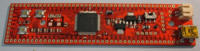
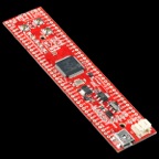
I've been using these for prototyping:
<400x102xUBW32_v24_SparkFun_sm.JPG.pagespeed.ic.NkWMNm0oSs.jpg> <09713-01b.jpeg>
based on a project here: http://www.schmalzhaus.com/UBW32/ - but there are other ways to do it. Microchip even have one. I'm thinking the SDCARD may be easier (just put the firmware on the SDCARD, switch it on and it will update), but the cpu has excellent usb support.
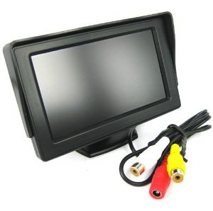
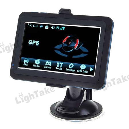
When you start thinking for the display unit, -> howto mounting this to the dashboard or window.
At the moment, I'm just playing with stuff like this:
<413mYL-A2kL._SX300_.jpg><41J-KCMFJWL._SY300_.jpg>
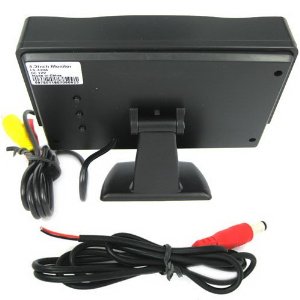
Cheap cheap cheap, but surprisingly good.
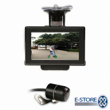
But, there are also ones like this:
<43or-35-tftlcd-display-windscreen-model-and-ccd-camera-315.jpg><url.jpeg>
We don't have the quantity for moulding ourselves, so we'll just have to find some end-run of cases and modify for the cable we need. Not too bad if all they have to do is punch a hole. The good news is that there are a lot of these GPS units / rearview monitors in Shenzhen (just across the border) so I don't think it will be too hard to find someone to do an end-run for us.
Regards, Mark.
On 11 Apr, 2013, at 5:18 PM, Nikki Gordon-Bloomfield <nikki@littlecollie.com> wrote:
Agreed with Michael!
Relays are very important, as some car owners (especially those with conversions) will want to use relays to control the timing of charging cycles etc.
I also like the idea of hiding the main unit and then having a smaller display. It should make the system look more professional, and give EV owners and builders an option to what they want.
Also, there needs to be a way we can have a programming port easily accessible for the portion of the hardware hidden. This will make it easier to upload software. Maybe a USB extension or DB9?
Nikki.
On 11 Apr 2013, at 10:02, Michael Jochum <mikeljo@mac.com> wrote:
Hi,
Am 11.04.2013 um 04:43 schrieb Mark Webb-Johnson <mark@webb-johnson.net>:
An optional second display (with second CPU) is probably the cleanest way. We would need to provide Power + Ground (2 or 3 wires) and serial (2 or 4 wires) - so that would be worst case 7 wires. Perhaps a RJ45 cable would be flexible - allowing us to just use CAT5 cables which are available in so many lengths and easy to connect/disconnect? If we use the CAN, then we need 2 more wires per CAN bus.
or a good sub-d 9. It is better for daily use. For one time installation RJ45 is ok. But when you remove and connect every day they are not very handy. For the communication between the two units you can use i2c or SPI. It is a question of the implementation. What is fast, easy, secure. Secure means that the data that was receive are the same that was send. CRC for example.
The optional display would perhaps be the best solution (rather than putting it all in one box). The combination of the two would be more expensive than one, but it would offer more flexibility (and the display-less version would be cheaper). The main OVMS unit could remain hidden in the car, and for those who want the display, they just add it on. OVMS would work with either the optional display or the smartphone via bluetooth display (or both).
I think this is a great solution. So anybody can get what he want. Buy first only the main unit. If he is satisfied (certain he will!) and want more then he can add the display unit.
What do people think? Is this a good compromise?
Main OVMS box 2x CAN ports 1x OBDII port BT (BLE) Wifi 3G GPS Optional display box 4.3" Display with touch Quick disconnect Optional cellphone display via BLE
Thats what i'm thinking for. :-)
Oh, i think i forget one point: - Potential free switch output (Relais, one or more) eventually in a separate box, as an add on. You remember that there was a question about this. But i think this is only an option of an option.............
When you start thinking for the display unit, -> howto mounting this to the dashboard or window.
Regarding the 'raw' mode - that was my surprise! Yes it should be possible to just software switch the OBDII controller chip into the serial / bluetooth port - both are just serial async - and then Torque/whatever should just work. But that would mean OVMS couldn't use the OBDII port while raw mode was in use. We could also do a 'shared' mode - but that would be a lot more work (to fully decode the OBDII controller protocol and support shared PID polling, initialisation and control).
Oh, i can surprise you. ;-) I think it is no problem when in raw mode that OVMS could not use the Port. This mode is for logging with external Tools, Hardware etc. only. And only for a short time. Or, you implement a mode that the OVMS do like a "ELM" interface. I mean it work like this. It acts like a CAN2BT interface with AT commands. And so anybody can use the App he want on the Smartphone he want over BLE.
Bye michael J.
Regards, Mark.
On 10 Apr, 2013, at 5:01 PM, Michael Jochum wrote:
Hi,
my two cents: - minimum 2 CAN Ports - BT - Wifi - 3G - GPS - Display with Touch (eventually in an separate case, if possible) - as an option use of the Smartphone as Display. But i prefer that the Module has its own
I know the Problems with the BT Stack on the iDevices. In the moment we can use the BT Stack, but what happen in the future? We talk about a non jailbreak device!
When we can separate the Display from the main unit, it is possible to cover the main unit. And with a "quick" release for the display it can secure in your pocket when you leave the car. Nice for twizzy i think. The second is that when we have more than one CAN Bus attached there are a lot of cables to the unit. Bringing this to a device mounted on the dash in a viewable area dont look good. I dont talk about a BT (or XBee) connection between the main unit and the display!!!!!! I mean a cable with a handy connector.
2 CPUs are nice ;-) Logging with GPS to an SD Card, with automatic transfer to my Homeserver (or the "Cloud") when the module connects to known Wifi Network(s) will be GREAT.
Could it be possible to switch the module in "raw" mode. So that the CAN Stream is available at the BT. So it can use as an "ELM" (or so) interface. With the same commands like a "standard" CAN-BT device. With the possibility to switch between the different CAN Buses. I think i remember you wrote something about this before!?
Bye Michael J.
Am 10.04.2013 um 04:21 schrieb Mark Webb-Johnson <mark@webb-johnson.net>:
Michael, Nikki, Kevin, etc,
The reason for the display/touchpad is twofold:
Real-time display of vehicle information (0-60 times, sensors, etc) Initial setup and monitoring of the OVMS module (avoiding SMS and making troubleshooting much easier)
The display does add complexity+cost, increases theft worries, and is a hassle.
I've previously kept away from using a smartphone as a display for a few reasons:
The smartphone runs hot It is not elegant Bluetooth is a 'bag of hurt' on Apple
To use a bluetooth v2 (the standard, with excellent support) module with Apple devices requires the module to be a part of the MFI (Made For iPhone) program. That is a nightmare. Now, more recent devices (iPhone 4S and above, plus very modern Android devices) support bluetooth v4 (BLE) and Apple _supposedly_ has relaxed the rules with that - so long as the functionality is not core (ie; we add it to the existing ovms apps, and not having a device won't stop the app from working), we can probably get it through (but this is at the whim of Apple's approval process). BLE (v4) modules are damn expensive - but significantly less expensive than a 4.3" LCD display with touchpad :-)
Others use WIFI as a way of bypassing Apple's restrictions, but that is nasty. You have to set the device as your wifi access point, and you then lose Internet connectivity.
If we went the use-the-smartphone-as-the-display route, that would reduce costs and complexity (even with BLE). We could do without the second CPU (limiting us to 2xCAN ports and 1xOBDII). I like Michael's idea of exposing some A/D and/or digital I/O ports that could be used to support other vehicle types. The displays are certainly easier to program and look a lot better.
We've also got 6 async ports on the PIC32MX795, so we could also expose the same display protocol that the smartphone apps would use via that - perhaps for a plug-in add-on display option?
Going that route would result in:
1x PIC32MX795 cpu for 2xCAN ports, 1xOBD-II main control tasks (always on) SD-Card Wifi Bluetooth (BLE) 3G+GPS
I/O exposed would be:
Pure OBDII (via standard DB9) connector OVMS standard DB9 connector (extended for second CAN bus) OVMS expansion connector (diagnostics, ICSP, plus A/D, digital I/O and async) USB (for firmware update) GSM antenna GPS antenna SD-Card (SIM slot internal is probably still best, to avoid theft concerns with the SIM)
Enclosure size would probably have to be bigger than the current one - perhaps the same width/height, just increase the length. I am a little concerned about Wifi and Bluetooth antennas - putting them on the motherboard modules is by far the easiest, but that won't work with a metal case.
Cost probably US$150 - US$170 range (bluetooth, wifi and 3G being responsible for this).
Regards, Mark.
On 10 Apr, 2013, at 2:30 AM, Michael Balzer wrote:
> > Am 09.04.2013 12:14, schrieb Nikki Gordon-Bloomfield: >> Using the Bluetooth serial connection, it should be possible for users to implement a GUI with existing smart phone technology. > > Oh I forgot: yes! That's the idea behind adding Bluetooth to the Twizplay, they could omit the LCD and use an App as the display device. > > That's really a good option I think! Would also keep cost down. > >> For Twizy owners that's an added bonus. There are no door locks, and getting in is as simple as reaching inside and pulling the door handle. > ...that's why most Twizplay owners currently use a special quick lock mount just for the Twizplay -- so you need both a mount for the display and one for your mobile phone... bad. > >> Moving forward, I think it'd be great if someone in the self-build community (You may have to work with someone else) could produce a raw "battery pack to OVMS" module, which enables those with converted or custom EVs to use the OVMS system using a standard set of protocols and Can messaging -- or perhaps direct using an add-on IO device? > That would make the OVMS an option for Ebike and Escooter drivers as well. I've got one of these: http://www.emco-elektroroller.de/elektroroller/novum.html > > ...just a simple chinese scooter, it doesn't have any data port, and it's only display is an analog voltage meter for the overall battery voltage -- you have to guess the SOC based on how deep the voltage drops under load. > > The most simple solution would be to provide two analog I/O ports to feed pack voltage and current (measured as voltage difference on a shunt) into the OVMS. The A/D conversion should be fast enough to provide at least 10 ms resolution, so we can implement an Ah counter in software. Also some digital I/O ports should be available to measure the distance driven (by a reed sensor mounted to a tyre) and maybe record some other system status. > > So, basically the same as available solutions like the "Cycle Analyst" or the "WattsUp" do, but with the added OVMS coolness. > > > Regards, > Michael > > -- > Michael Balzer * Paradestr. 8 * D-42107 Wuppertal > Fon 0202 / 272 2201 * Handy 0176 / 206 989 26 > <dexter.vcf>_______________________________________________ > OvmsDev mailing list > OvmsDev@lists.teslaclub.hk > http://lists.teslaclub.hk/mailman/listinfo/ovmsdev
_______________________________________________ OvmsDev mailing list OvmsDev@lists.teslaclub.hk http://lists.teslaclub.hk/mailman/listinfo/ovmsdev
_______________________________________________ OvmsDev mailing list OvmsDev@lists.teslaclub.hk http://lists.teslaclub.hk/mailman/listinfo/ovmsdev
_______________________________________________ OvmsDev mailing list OvmsDev@lists.teslaclub.hk http://lists.teslaclub.hk/mailman/listinfo/ovmsdev
_______________________________________________ OvmsDev mailing list OvmsDev@lists.teslaclub.hk http://lists.teslaclub.hk/mailman/listinfo/ovmsdev
_______________________________________________ OvmsDev mailing list OvmsDev@lists.teslaclub.hk http://lists.teslaclub.hk/mailman/listinfo/ovmsdev
_______________________________________________ OvmsDev mailing list OvmsDev@lists.teslaclub.hk http://lists.teslaclub.hk/mailman/listinfo/ovmsdev
I've been working with the China guys regarding bluetooth (and wifi) for a more sophisticated OVMS, but it really is painful. My conclusions: Bluetooth 2.1 works everywhere, is cheap (especially SPP protocol). Android: Support is excellent, good libraries and no problem iPhone: Impossible. Need MFI program membership and Apple-tax Bluetooth BLE is very flexible, more expensive (at the moment), and roll-your-own protocol. Android: Doesn't properly support it. Varies by device, and even latest 4.2.x doesn't support BLE. iPhone: Latest devices only, but fantastic support, and no need for MFI program Dual-mode Bluetooth 2.1 and BLE In theory, a good solution v2.1 bluetooth and v4.0 BLE are two completely different beasts But, just too damn expensive and complex Wifi Simple AP mode (supported by some wifi modules) allows us to connect the phone to the OVMS module over wifi. Phone client. Module AP. But, once connected, we lose Internet connectivity on the phone. This is the method used by OBDII apps on the iPhone, to get around Apple's restrictions. If we had bluetooth, we could solve the (a) setup problem, and (b) real-time display. Can you imagine that Parrot unit as a real-time display for OVMS, over bluetooth! Dual mode bluetooth BLE (both v4.0 BLE and v2.1 SPP) is going to be hellishly expensive and complex to implement. I really haven't come up with a perfect solution. The ideal solution would be for Apple to support SPP profile in the bluetooth v2.1 stack, but who knows what is coming in iOS 7? My gut feeling is to live with a compromise. There are simple little bluetooth v2.1 HC-05 style modules that support SPP (basically, a serial port over bluetooth) - very very cheap to add. They will work with Android, but not iPhone. For iPhone we could use wifi AP (for initial setup and/or real-time display). The Android App could support both wifi and bluetooth v2.1 SPP, the iPhone App would support just wifi. Regards, Mark. On 11 Apr, 2013, at 11:05 PM, Mark Webb-Johnson <mark@webb-johnson.net> wrote:
Michael, Nikki,
or a good sub-d 9
Or sub-d 15? Just a bit klunky and hard to route through vehicle areas. I guess if it goes into the back of the box it is fine.
For the communication between the two units you can use i2c or SPI.
I'm a little worried about cable length and interference. What is limit for i2c? Async may be simpler (with some protocol on top for error-checking).
- Potential free switch output (Relais, one or more) eventually in a separate box, as an add on.
My suggestion was to include an expansion port (diagnostics, ICSP, plus A/D, digital I/O and async). I think it is better to put the relays in a separate box. It would be nice to have home-control (zigbee/whatever), but that is another mess with so many competing standards and hassle. With bluetooth, wifi and 3G I guess we'll be ok.
Also, there needs to be a way we can have a programming port easily accessible for the portion of the hardware hidden.
The incremental programming can be via USB. So, a normal usb extender can be used if necessary (or just a usb cable).
We'll also have ICSP (6 pin?), but that shouldn't be needed for day-to-day.
I've been using these for prototyping:
<400x102xUBW32_v24_SparkFun_sm.JPG.pagespeed.ic.NkWMNm0oSs.jpg> <09713-01b.jpeg>
based on a project here: http://www.schmalzhaus.com/UBW32/ - but there are other ways to do it. Microchip even have one. I'm thinking the SDCARD may be easier (just put the firmware on the SDCARD, switch it on and it will update), but the cpu has excellent usb support.
When you start thinking for the display unit, -> howto mounting this to the dashboard or window.
At the moment, I'm just playing with stuff like this:
<413mYL-A2kL._SX300_.jpg><41J-KCMFJWL._SY300_.jpg>
Cheap cheap cheap, but surprisingly good.
But, there are also ones like this:
<43or-35-tftlcd-display-windscreen-model-and-ccd-camera-315.jpg><url.jpeg>
We don't have the quantity for moulding ourselves, so we'll just have to find some end-run of cases and modify for the cable we need. Not too bad if all they have to do is punch a hole. The good news is that there are a lot of these GPS units / rearview monitors in Shenzhen (just across the border) so I don't think it will be too hard to find someone to do an end-run for us.
Regards, Mark.
On 11 Apr, 2013, at 5:18 PM, Nikki Gordon-Bloomfield <nikki@littlecollie.com> wrote:
Agreed with Michael!
Relays are very important, as some car owners (especially those with conversions) will want to use relays to control the timing of charging cycles etc.
I also like the idea of hiding the main unit and then having a smaller display. It should make the system look more professional, and give EV owners and builders an option to what they want.
Also, there needs to be a way we can have a programming port easily accessible for the portion of the hardware hidden. This will make it easier to upload software. Maybe a USB extension or DB9?
Nikki.
On 11 Apr 2013, at 10:02, Michael Jochum <mikeljo@mac.com> wrote:
Hi,
Am 11.04.2013 um 04:43 schrieb Mark Webb-Johnson <mark@webb-johnson.net>:
An optional second display (with second CPU) is probably the cleanest way. We would need to provide Power + Ground (2 or 3 wires) and serial (2 or 4 wires) - so that would be worst case 7 wires. Perhaps a RJ45 cable would be flexible - allowing us to just use CAT5 cables which are available in so many lengths and easy to connect/disconnect? If we use the CAN, then we need 2 more wires per CAN bus.
or a good sub-d 9. It is better for daily use. For one time installation RJ45 is ok. But when you remove and connect every day they are not very handy. For the communication between the two units you can use i2c or SPI. It is a question of the implementation. What is fast, easy, secure. Secure means that the data that was receive are the same that was send. CRC for example.
The optional display would perhaps be the best solution (rather than putting it all in one box). The combination of the two would be more expensive than one, but it would offer more flexibility (and the display-less version would be cheaper). The main OVMS unit could remain hidden in the car, and for those who want the display, they just add it on. OVMS would work with either the optional display or the smartphone via bluetooth display (or both).
I think this is a great solution. So anybody can get what he want. Buy first only the main unit. If he is satisfied (certain he will!) and want more then he can add the display unit.
What do people think? Is this a good compromise?
Main OVMS box 2x CAN ports 1x OBDII port BT (BLE) Wifi 3G GPS Optional display box 4.3" Display with touch Quick disconnect Optional cellphone display via BLE
Thats what i'm thinking for. :-)
Oh, i think i forget one point: - Potential free switch output (Relais, one or more) eventually in a separate box, as an add on. You remember that there was a question about this. But i think this is only an option of an option.............
When you start thinking for the display unit, -> howto mounting this to the dashboard or window.
Regarding the 'raw' mode - that was my surprise! Yes it should be possible to just software switch the OBDII controller chip into the serial / bluetooth port - both are just serial async - and then Torque/whatever should just work. But that would mean OVMS couldn't use the OBDII port while raw mode was in use. We could also do a 'shared' mode - but that would be a lot more work (to fully decode the OBDII controller protocol and support shared PID polling, initialisation and control).
Oh, i can surprise you. ;-) I think it is no problem when in raw mode that OVMS could not use the Port. This mode is for logging with external Tools, Hardware etc. only. And only for a short time. Or, you implement a mode that the OVMS do like a "ELM" interface. I mean it work like this. It acts like a CAN2BT interface with AT commands. And so anybody can use the App he want on the Smartphone he want over BLE.
Bye michael J.
Regards, Mark.
On 10 Apr, 2013, at 5:01 PM, Michael Jochum wrote:
Hi,
my two cents: - minimum 2 CAN Ports - BT - Wifi - 3G - GPS - Display with Touch (eventually in an separate case, if possible) - as an option use of the Smartphone as Display. But i prefer that the Module has its own
I know the Problems with the BT Stack on the iDevices. In the moment we can use the BT Stack, but what happen in the future? We talk about a non jailbreak device!
When we can separate the Display from the main unit, it is possible to cover the main unit. And with a "quick" release for the display it can secure in your pocket when you leave the car. Nice for twizzy i think. The second is that when we have more than one CAN Bus attached there are a lot of cables to the unit. Bringing this to a device mounted on the dash in a viewable area dont look good. I dont talk about a BT (or XBee) connection between the main unit and the display!!!!!! I mean a cable with a handy connector.
2 CPUs are nice ;-) Logging with GPS to an SD Card, with automatic transfer to my Homeserver (or the "Cloud") when the module connects to known Wifi Network(s) will be GREAT.
Could it be possible to switch the module in "raw" mode. So that the CAN Stream is available at the BT. So it can use as an "ELM" (or so) interface. With the same commands like a "standard" CAN-BT device. With the possibility to switch between the different CAN Buses. I think i remember you wrote something about this before!?
Bye Michael J.
Am 10.04.2013 um 04:21 schrieb Mark Webb-Johnson <mark@webb-johnson.net>:
Michael, Nikki, Kevin, etc,
The reason for the display/touchpad is twofold:
Real-time display of vehicle information (0-60 times, sensors, etc) Initial setup and monitoring of the OVMS module (avoiding SMS and making troubleshooting much easier)
The display does add complexity+cost, increases theft worries, and is a hassle.
I've previously kept away from using a smartphone as a display for a few reasons:
The smartphone runs hot It is not elegant Bluetooth is a 'bag of hurt' on Apple
To use a bluetooth v2 (the standard, with excellent support) module with Apple devices requires the module to be a part of the MFI (Made For iPhone) program. That is a nightmare. Now, more recent devices (iPhone 4S and above, plus very modern Android devices) support bluetooth v4 (BLE) and Apple _supposedly_ has relaxed the rules with that - so long as the functionality is not core (ie; we add it to the existing ovms apps, and not having a device won't stop the app from working), we can probably get it through (but this is at the whim of Apple's approval process). BLE (v4) modules are damn expensive - but significantly less expensive than a 4.3" LCD display with touchpad :-)
Others use WIFI as a way of bypassing Apple's restrictions, but that is nasty. You have to set the device as your wifi access point, and you then lose Internet connectivity.
If we went the use-the-smartphone-as-the-display route, that would reduce costs and complexity (even with BLE). We could do without the second CPU (limiting us to 2xCAN ports and 1xOBDII). I like Michael's idea of exposing some A/D and/or digital I/O ports that could be used to support other vehicle types. The displays are certainly easier to program and look a lot better.
We've also got 6 async ports on the PIC32MX795, so we could also expose the same display protocol that the smartphone apps would use via that - perhaps for a plug-in add-on display option?
Going that route would result in:
1x PIC32MX795 cpu for 2xCAN ports, 1xOBD-II main control tasks (always on) SD-Card Wifi Bluetooth (BLE) 3G+GPS
I/O exposed would be:
Pure OBDII (via standard DB9) connector OVMS standard DB9 connector (extended for second CAN bus) OVMS expansion connector (diagnostics, ICSP, plus A/D, digital I/O and async) USB (for firmware update) GSM antenna GPS antenna SD-Card (SIM slot internal is probably still best, to avoid theft concerns with the SIM)
Enclosure size would probably have to be bigger than the current one - perhaps the same width/height, just increase the length. I am a little concerned about Wifi and Bluetooth antennas - putting them on the motherboard modules is by far the easiest, but that won't work with a metal case.
Cost probably US$150 - US$170 range (bluetooth, wifi and 3G being responsible for this).
Regards, Mark.
On 10 Apr, 2013, at 2:30 AM, Michael Balzer wrote:
> > Am 09.04.2013 12:14, schrieb Nikki Gordon-Bloomfield: >> Using the Bluetooth serial connection, it should be possible for users to implement a GUI with existing smart phone technology. > > Oh I forgot: yes! That's the idea behind adding Bluetooth to the Twizplay, they could omit the LCD and use an App as the display device. > > That's really a good option I think! Would also keep cost down. > >> For Twizy owners that's an added bonus. There are no door locks, and getting in is as simple as reaching inside and pulling the door handle. > ...that's why most Twizplay owners currently use a special quick lock mount just for the Twizplay -- so you need both a mount for the display and one for your mobile phone... bad. > >> Moving forward, I think it'd be great if someone in the self-build community (You may have to work with someone else) could produce a raw "battery pack to OVMS" module, which enables those with converted or custom EVs to use the OVMS system using a standard set of protocols and Can messaging -- or perhaps direct using an add-on IO device? > That would make the OVMS an option for Ebike and Escooter drivers as well. I've got one of these: http://www.emco-elektroroller.de/elektroroller/novum.html > > ...just a simple chinese scooter, it doesn't have any data port, and it's only display is an analog voltage meter for the overall battery voltage -- you have to guess the SOC based on how deep the voltage drops under load. > > The most simple solution would be to provide two analog I/O ports to feed pack voltage and current (measured as voltage difference on a shunt) into the OVMS. The A/D conversion should be fast enough to provide at least 10 ms resolution, so we can implement an Ah counter in software. Also some digital I/O ports should be available to measure the distance driven (by a reed sensor mounted to a tyre) and maybe record some other system status. > > So, basically the same as available solutions like the "Cycle Analyst" or the "WattsUp" do, but with the added OVMS coolness. > > > Regards, > Michael > > -- > Michael Balzer * Paradestr. 8 * D-42107 Wuppertal > Fon 0202 / 272 2201 * Handy 0176 / 206 989 26 > <dexter.vcf>_______________________________________________ > OvmsDev mailing list > OvmsDev@lists.teslaclub.hk > http://lists.teslaclub.hk/mailman/listinfo/ovmsdev
_______________________________________________ OvmsDev mailing list OvmsDev@lists.teslaclub.hk http://lists.teslaclub.hk/mailman/listinfo/ovmsdev
_______________________________________________ OvmsDev mailing list OvmsDev@lists.teslaclub.hk http://lists.teslaclub.hk/mailman/listinfo/ovmsdev
_______________________________________________ OvmsDev mailing list OvmsDev@lists.teslaclub.hk http://lists.teslaclub.hk/mailman/listinfo/ovmsdev
_______________________________________________ OvmsDev mailing list OvmsDev@lists.teslaclub.hk http://lists.teslaclub.hk/mailman/listinfo/ovmsdev
_______________________________________________ OvmsDev mailing list OvmsDev@lists.teslaclub.hk http://lists.teslaclub.hk/mailman/listinfo/ovmsdev
_______________________________________________ OvmsDev mailing list OvmsDev@lists.teslaclub.hk http://lists.teslaclub.hk/mailman/listinfo/ovmsdev

Hi Mark, IMO it would be great if the next OVMS hardware version could be compatible with the 'Generalised Vehicle Control Unit' being promoted by Jack Ricard (EVTV) and a bunch of developers. This would allow us to move towards a generic and open architecture for future EV control. I'm happy to provide details of the GVCU hardware/software if you think that would be helpful. I think we also want to make any new hardware sufficiently 'sexy' to encourage people to get involved for the benefit of all. While projects like CANary and LEAFSCAN are admirable it's a shame that so much effort is being expended on projects other than OVMS :-) Keep up the good work! [http://www.zerocarbonworld.org/images/logo.png] Kevin Sharpe | Founder & Patron Tel: +44 122 566 7544 ext: 800 | Skype: zerocarbonworld kevin.sharpe@zerocarbonworld.org <mailto:kevin.sharpe@zerocarbonworld.org> | www.zerocarbonworld.org<http://www.zerocarbonworld.org/> | twitter.com/zerocarbonworld<http://twitter.com/ZCWcharlie> [http://www.zerocarbonworld.org/images/email-signatures_06.png] Zero Carbon World is a UK Registered Charity #1141347 From: Mark Webb-Johnson <mark@webb-johnson.net<mailto:mark@webb-johnson.net>> Reply-To: OVMS Developers <ovmsdev@lists.teslaclub.hk<mailto:ovmsdev@lists.teslaclub.hk>> Date: Tuesday, 9 April 2013 07:21 To: OVMS Developers <ovmsdev@lists.teslaclub.hk<mailto:ovmsdev@lists.teslaclub.hk>> Subject: [Ovmsdev] More sophisticated hardware Long post - apologies... I'm not suggesting changing the current hardware offering, but coming up with something more powerful to offer along side it. Requirements listed include: * WIFI * Bluetooth * Display * Full OBD-II * More CAN buses * 3G * SD-Card for data logging capability We've been talking about this for a while, and have tried various approaches. It comes down to a choice between: * Low power embedded PIC style * High power Linux arm style My personal preference is for low-power - especially given the 12V issues we've seen. A couple of things have come together over the past few months, and there are some interesting opportunities: * I've been looking at the PIC32MX795 microcontroller. 128KB of RAM, 512KB flash. 6 async ports. 2 CAN buses. etc. * Using controller-based touch-screen LCDs is hellishly expensive. But, Microchip have a neat solution. Using an off-chip memory buffer (or on chip ram for lower resolutions) and DMA transfers, a 4.3" LCD WQVGA resolution display (with touchscreen) can be interfaced for a fraction of the cost of a controller-based display, using just 5% to 10% of the CPU. * 3G is possible - just need to work out the required frequencies to see if we need (a) the tri-band version, or (b) two different dual-band versions. * Full OBD-II is relatively easy - standard outputs interfaces via async serial ELM327 style (using the newer STN1110). * Single-wire CAN is also possible. * The PIC32s have USB on-board (for serial, or firmware upload). * SD-Card is relatively easy (libraries are available, and plenty of I/O PINs for the I2C controller). * Bluetooth modules are easy (async serial interface). * Wifi is possible (for wifi client based setups as an alternative to 3G - hotspot is trickier). The design I've been looking at includes: * A 4.3" multi-touch 400x240 resolution LCD display. * A primary PIC32MX795 cpu for 2xCAN ports, 1xOBD-II main control tasks (always on). * A secondary PIC32MX795 cpu with LCC setup to drive the LCD display and touchpad - this is just for UI. * SD-Card * Wifi * Bluetooth * 3G+GPS We could use the 2xCAN ports on the second (display) CPU as well, if we needed them - although the basic setup above already has 3 CAN ports (2 direct and 1 via OBD-II). The primary controller has power control and can power down the other parts of the system (particularly power hungry systems like display) when the car is off. It seems to me that the more advanced portion of our user base wants to do some sophisticated stuff, and there is a very large community of users out there using things like the DashDAQ for real-time logging and display of vehicle metrics. The DashDAQ costs US$549 (plus extras), and doesn't have wifi, bluetooth, 3G - it only works on OBD-II and is 'closed' (although you can do some screen design in it). Feature-wise, I'm looking at something like the DashDAQ. The ability to make screens with real-time metrics, as well as an in-car display. Couple that with logging capability for both low-level CAN/OBD-II traffic and high-level gps-based plots. Wifi-connectivity to home wifis for garages with no 3G coverage, and bluetooth for cell-phone connectivity. Plus, all the existing OVMS features. I'm guessing that the hardware to do all of the above would be about double what we have now (so around US$200). The biggest cost items are the 4.3" display and 3G module. CPUs are cheap (about US$10 each). There are quite a large number of ancillary components (especially for OBD-II), but it should fit in an enclosure behind a 4.3" display. Other than bread-boarding some mock-ups, to see if this is feasible, I haven't done any extensive work on the above. What do people think? Is this something people would want? A way to grow the community? Or, is there a better way of doing it? Regards, Mark.
Kevin, I did have some discussions a while ago with the Macchina guys - they were wanting to support OVMS (server and apps) from their module. They were driving that, and not sure where it went. I like the way they are supporting the conversion market, and it is good that EVTV chose them. Regards, Mark. On 9 Apr, 2013, at 11:15 PM, Kevin Sharpe ZCW wrote:
Hi Mark,
IMO it would be great if the next OVMS hardware version could be compatible with the 'Generalised Vehicle Control Unit' being promoted by Jack Ricard (EVTV) and a bunch of developers. This would allow us to move towards a generic and open architecture for future EV control. I'm happy to provide details of the GVCU hardware/software if you think that would be helpful.
I think we also want to make any new hardware sufficiently 'sexy' to encourage people to get involved for the benefit of all. While projects like CANary and LEAFSCAN are admirable it's a shame that so much effort is being expended on projects other than OVMS :-)
Keep up the good work! Kevin Sharpe | Founder & Patron Tel: +44 122 566 7544 ext: 800 | Skype: zerocarbonworld kevin.sharpe@zerocarbonworld.org | www.zerocarbonworld.org | twitter.com/zerocarbonworld
Zero Carbon World is a UK Registered Charity #1141347 From: Mark Webb-Johnson <mark@webb-johnson.net> Reply-To: OVMS Developers <ovmsdev@lists.teslaclub.hk> Date: Tuesday, 9 April 2013 07:21 To: OVMS Developers <ovmsdev@lists.teslaclub.hk> Subject: [Ovmsdev] More sophisticated hardware
Long post - apologies...
I'm not suggesting changing the current hardware offering, but coming up with something more powerful to offer along side it. Requirements listed include:
WIFI Bluetooth Display Full OBD-II More CAN buses 3G SD-Card for data logging capability
We've been talking about this for a while, and have tried various approaches. It comes down to a choice between:
Low power embedded PIC style High power Linux arm style
My personal preference is for low-power - especially given the 12V issues we've seen.
A couple of things have come together over the past few months, and there are some interesting opportunities:
I've been looking at the PIC32MX795 microcontroller. 128KB of RAM, 512KB flash. 6 async ports. 2 CAN buses. etc. Using controller-based touch-screen LCDs is hellishly expensive. But, Microchip have a neat solution. Using an off-chip memory buffer (or on chip ram for lower resolutions) and DMA transfers, a 4.3" LCD WQVGA resolution display (with touchscreen) can be interfaced for a fraction of the cost of a controller-based display, using just 5% to 10% of the CPU. 3G is possible - just need to work out the required frequencies to see if we need (a) the tri-band version, or (b) two different dual-band versions. Full OBD-II is relatively easy - standard outputs interfaces via async serial ELM327 style (using the newer STN1110). Single-wire CAN is also possible. The PIC32s have USB on-board (for serial, or firmware upload). SD-Card is relatively easy (libraries are available, and plenty of I/O PINs for the I2C controller). Bluetooth modules are easy (async serial interface). Wifi is possible (for wifi client based setups as an alternative to 3G - hotspot is trickier).
The design I've been looking at includes:
A 4.3" multi-touch 400x240 resolution LCD display. A primary PIC32MX795 cpu for 2xCAN ports, 1xOBD-II main control tasks (always on). A secondary PIC32MX795 cpu with LCC setup to drive the LCD display and touchpad - this is just for UI. SD-Card Wifi Bluetooth 3G+GPS
We could use the 2xCAN ports on the second (display) CPU as well, if we needed them - although the basic setup above already has 3 CAN ports (2 direct and 1 via OBD-II). The primary controller has power control and can power down the other parts of the system (particularly power hungry systems like display) when the car is off.
It seems to me that the more advanced portion of our user base wants to do some sophisticated stuff, and there is a very large community of users out there using things like the DashDAQ for real-time logging and display of vehicle metrics.
The DashDAQ costs US$549 (plus extras), and doesn't have wifi, bluetooth, 3G - it only works on OBD-II and is 'closed' (although you can do some screen design in it).
Feature-wise, I'm looking at something like the DashDAQ. The ability to make screens with real-time metrics, as well as an in-car display. Couple that with logging capability for both low-level CAN/OBD-II traffic and high-level gps-based plots. Wifi-connectivity to home wifis for garages with no 3G coverage, and bluetooth for cell-phone connectivity. Plus, all the existing OVMS features.
I'm guessing that the hardware to do all of the above would be about double what we have now (so around US$200). The biggest cost items are the 4.3" display and 3G module. CPUs are cheap (about US$10 each). There are quite a large number of ancillary components (especially for OBD-II), but it should fit in an enclosure behind a 4.3" display.
Other than bread-boarding some mock-ups, to see if this is feasible, I haven't done any extensive work on the above.
What do people think? Is this something people would want? A way to grow the community? Or, is there a better way of doing it?
Regards, Mark.
_______________________________________________ OvmsDev mailing list OvmsDev@lists.teslaclub.hk http://lists.teslaclub.hk/mailman/listinfo/ovmsdev
Many thanks Mark. I believe that GVCU has moved on from Macchina and that might explain the 'radio silence'. I'll reach out to EVTV and find out what the plans are. All the best, Kevin On 10 Apr 2013, at 02:56, "Mark Webb-Johnson" <mark@webb-johnson.net<mailto:mark@webb-johnson.net>> wrote: Kevin, I did have some discussions a while ago with the Macchina guys - they were wanting to support OVMS (server and apps) from their module. They were driving that, and not sure where it went. I like the way they are supporting the conversion market, and it is good that EVTV chose them. Regards, Mark. On 9 Apr, 2013, at 11:15 PM, Kevin Sharpe ZCW wrote: Hi Mark, IMO it would be great if the next OVMS hardware version could be compatible with the 'Generalised Vehicle Control Unit' being promoted by Jack Ricard (EVTV) and a bunch of developers. This would allow us to move towards a generic and open architecture for future EV control. I'm happy to provide details of the GVCU hardware/software if you think that would be helpful. I think we also want to make any new hardware sufficiently 'sexy' to encourage people to get involved for the benefit of all. While projects like CANary and LEAFSCAN are admirable it's a shame that so much effort is being expended on projects other than OVMS :-) Keep up the good work! [http://www.zerocarbonworld.org/images/logo.png] Kevin Sharpe | Founder & Patron Tel: +44 122 566 7544 ext: 800 | Skype: zerocarbonworld kevin.sharpe@zerocarbonworld.org <mailto:kevin.sharpe@zerocarbonworld.org> | www.zerocarbonworld.org<http://www.zerocarbonworld.org/> | twitter.com/zerocarbonworld<http://twitter.com/ZCWcharlie> [http://www.zerocarbonworld.org/images/email-signatures_06.png] Zero Carbon World is a UK Registered Charity #1141347 From: Mark Webb-Johnson <mark@webb-johnson.net<mailto:mark@webb-johnson.net>> Reply-To: OVMS Developers <ovmsdev@lists.teslaclub.hk<mailto:ovmsdev@lists.teslaclub.hk>> Date: Tuesday, 9 April 2013 07:21 To: OVMS Developers <ovmsdev@lists.teslaclub.hk<mailto:ovmsdev@lists.teslaclub.hk>> Subject: [Ovmsdev] More sophisticated hardware Long post - apologies... I'm not suggesting changing the current hardware offering, but coming up with something more powerful to offer along side it. Requirements listed include: * WIFI * Bluetooth * Display * Full OBD-II * More CAN buses * 3G * SD-Card for data logging capability We've been talking about this for a while, and have tried various approaches. It comes down to a choice between: * Low power embedded PIC style * High power Linux arm style My personal preference is for low-power - especially given the 12V issues we've seen. A couple of things have come together over the past few months, and there are some interesting opportunities: * I've been looking at the PIC32MX795 microcontroller. 128KB of RAM, 512KB flash. 6 async ports. 2 CAN buses. etc. * Using controller-based touch-screen LCDs is hellishly expensive. But, Microchip have a neat solution. Using an off-chip memory buffer (or on chip ram for lower resolutions) and DMA transfers, a 4.3" LCD WQVGA resolution display (with touchscreen) can be interfaced for a fraction of the cost of a controller-based display, using just 5% to 10% of the CPU. * 3G is possible - just need to work out the required frequencies to see if we need (a) the tri-band version, or (b) two different dual-band versions. * Full OBD-II is relatively easy - standard outputs interfaces via async serial ELM327 style (using the newer STN1110). * Single-wire CAN is also possible. * The PIC32s have USB on-board (for serial, or firmware upload). * SD-Card is relatively easy (libraries are available, and plenty of I/O PINs for the I2C controller). * Bluetooth modules are easy (async serial interface). * Wifi is possible (for wifi client based setups as an alternative to 3G - hotspot is trickier). The design I've been looking at includes: * A 4.3" multi-touch 400x240 resolution LCD display. * A primary PIC32MX795 cpu for 2xCAN ports, 1xOBD-II main control tasks (always on). * A secondary PIC32MX795 cpu with LCC setup to drive the LCD display and touchpad - this is just for UI. * SD-Card * Wifi * Bluetooth * 3G+GPS We could use the 2xCAN ports on the second (display) CPU as well, if we needed them - although the basic setup above already has 3 CAN ports (2 direct and 1 via OBD-II). The primary controller has power control and can power down the other parts of the system (particularly power hungry systems like display) when the car is off. It seems to me that the more advanced portion of our user base wants to do some sophisticated stuff, and there is a very large community of users out there using things like the DashDAQ for real-time logging and display of vehicle metrics. The DashDAQ costs US$549 (plus extras), and doesn't have wifi, bluetooth, 3G - it only works on OBD-II and is 'closed' (although you can do some screen design in it). Feature-wise, I'm looking at something like the DashDAQ. The ability to make screens with real-time metrics, as well as an in-car display. Couple that with logging capability for both low-level CAN/OBD-II traffic and high-level gps-based plots. Wifi-connectivity to home wifis for garages with no 3G coverage, and bluetooth for cell-phone connectivity. Plus, all the existing OVMS features. I'm guessing that the hardware to do all of the above would be about double what we have now (so around US$200). The biggest cost items are the 4.3" display and 3G module. CPUs are cheap (about US$10 each). There are quite a large number of ancillary components (especially for OBD-II), but it should fit in an enclosure behind a 4.3" display. Other than bread-boarding some mock-ups, to see if this is feasible, I haven't done any extensive work on the above. What do people think? Is this something people would want? A way to grow the community? Or, is there a better way of doing it? Regards, Mark. _______________________________________________ OvmsDev mailing list OvmsDev@lists.teslaclub.hk<mailto:OvmsDev@lists.teslaclub.hk> http://lists.teslaclub.hk/mailman/listinfo/ovmsdev _______________________________________________ OvmsDev mailing list OvmsDev@lists.teslaclub.hk<mailto:OvmsDev@lists.teslaclub.hk> http://lists.teslaclub.hk/mailman/listinfo/ovmsdev
It wouldn't surprise me. I think the Arduino is good for generalised low-speed control, but I would be concerned using it for thinks like brakes / stability / traction control / etc. One discussion I had with the guys was also whether the comms was best done in the same control unit. I know it is cost-effective, but I really like separating this. Look at the Tesla Model S - the big 17" display computer is separate from the VMS. If the big 17" display goes, you can still drive (slow down, steer, brake, stop, etc) the car. I really think OVMS is a good fit the the conversions market. If we bring out plenty of A/D, digital I/O and Async ports, in the more sophisticated hardware, then we should be very usable for them (as well as having the side affect of garage door control, etc :-) Regards, Mark. On 10 Apr, 2013, at 3:32 PM, Kevin Sharpe ZCW wrote:
Many thanks Mark.
I believe that GVCU has moved on from Macchina and that might explain the 'radio silence'.
I'll reach out to EVTV and find out what the plans are.
All the best,
Kevin
On 10 Apr 2013, at 02:56, "Mark Webb-Johnson" <mark@webb-johnson.net> wrote:
Kevin,
I did have some discussions a while ago with the Macchina guys - they were wanting to support OVMS (server and apps) from their module. They were driving that, and not sure where it went.
I like the way they are supporting the conversion market, and it is good that EVTV chose them.
Regards, Mark.
On 9 Apr, 2013, at 11:15 PM, Kevin Sharpe ZCW wrote:
Hi Mark,
IMO it would be great if the next OVMS hardware version could be compatible with the 'Generalised Vehicle Control Unit' being promoted by Jack Ricard (EVTV) and a bunch of developers. This would allow us to move towards a generic and open architecture for future EV control. I'm happy to provide details of the GVCU hardware/software if you think that would be helpful.
I think we also want to make any new hardware sufficiently 'sexy' to encourage people to get involved for the benefit of all. While projects like CANary and LEAFSCAN are admirable it's a shame that so much effort is being expended on projects other than OVMS :-)
Keep up the good work! Kevin Sharpe | Founder & Patron Tel: +44 122 566 7544 ext: 800 | Skype: zerocarbonworld kevin.sharpe@zerocarbonworld.org | www.zerocarbonworld.org | twitter.com/zerocarbonworld
Zero Carbon World is a UK Registered Charity #1141347 From: Mark Webb-Johnson <mark@webb-johnson.net> Reply-To: OVMS Developers <ovmsdev@lists.teslaclub.hk> Date: Tuesday, 9 April 2013 07:21 To: OVMS Developers <ovmsdev@lists.teslaclub.hk> Subject: [Ovmsdev] More sophisticated hardware
Long post - apologies...
I'm not suggesting changing the current hardware offering, but coming up with something more powerful to offer along side it. Requirements listed include:
WIFI Bluetooth Display Full OBD-II More CAN buses 3G SD-Card for data logging capability
We've been talking about this for a while, and have tried various approaches. It comes down to a choice between:
Low power embedded PIC style High power Linux arm style
My personal preference is for low-power - especially given the 12V issues we've seen.
A couple of things have come together over the past few months, and there are some interesting opportunities:
I've been looking at the PIC32MX795 microcontroller. 128KB of RAM, 512KB flash. 6 async ports. 2 CAN buses. etc. Using controller-based touch-screen LCDs is hellishly expensive. But, Microchip have a neat solution. Using an off-chip memory buffer (or on chip ram for lower resolutions) and DMA transfers, a 4.3" LCD WQVGA resolution display (with touchscreen) can be interfaced for a fraction of the cost of a controller-based display, using just 5% to 10% of the CPU. 3G is possible - just need to work out the required frequencies to see if we need (a) the tri-band version, or (b) two different dual-band versions. Full OBD-II is relatively easy - standard outputs interfaces via async serial ELM327 style (using the newer STN1110). Single-wire CAN is also possible. The PIC32s have USB on-board (for serial, or firmware upload). SD-Card is relatively easy (libraries are available, and plenty of I/O PINs for the I2C controller). Bluetooth modules are easy (async serial interface). Wifi is possible (for wifi client based setups as an alternative to 3G - hotspot is trickier).
The design I've been looking at includes:
A 4.3" multi-touch 400x240 resolution LCD display. A primary PIC32MX795 cpu for 2xCAN ports, 1xOBD-II main control tasks (always on). A secondary PIC32MX795 cpu with LCC setup to drive the LCD display and touchpad - this is just for UI. SD-Card Wifi Bluetooth 3G+GPS
We could use the 2xCAN ports on the second (display) CPU as well, if we needed them - although the basic setup above already has 3 CAN ports (2 direct and 1 via OBD-II). The primary controller has power control and can power down the other parts of the system (particularly power hungry systems like display) when the car is off.
It seems to me that the more advanced portion of our user base wants to do some sophisticated stuff, and there is a very large community of users out there using things like the DashDAQ for real-time logging and display of vehicle metrics.
The DashDAQ costs US$549 (plus extras), and doesn't have wifi, bluetooth, 3G - it only works on OBD-II and is 'closed' (although you can do some screen design in it).
Feature-wise, I'm looking at something like the DashDAQ. The ability to make screens with real-time metrics, as well as an in-car display. Couple that with logging capability for both low-level CAN/OBD-II traffic and high-level gps-based plots. Wifi-connectivity to home wifis for garages with no 3G coverage, and bluetooth for cell-phone connectivity. Plus, all the existing OVMS features.
I'm guessing that the hardware to do all of the above would be about double what we have now (so around US$200). The biggest cost items are the 4.3" display and 3G module. CPUs are cheap (about US$10 each). There are quite a large number of ancillary components (especially for OBD-II), but it should fit in an enclosure behind a 4.3" display.
Other than bread-boarding some mock-ups, to see if this is feasible, I haven't done any extensive work on the above.
What do people think? Is this something people would want? A way to grow the community? Or, is there a better way of doing it?
Regards, Mark.
_______________________________________________ OvmsDev mailing list OvmsDev@lists.teslaclub.hk http://lists.teslaclub.hk/mailman/listinfo/ovmsdev
_______________________________________________ OvmsDev mailing list OvmsDev@lists.teslaclub.hk http://lists.teslaclub.hk/mailman/listinfo/ovmsdev
OvmsDev mailing list OvmsDev@lists.teslaclub.hk http://lists.teslaclub.hk/mailman/listinfo/ovmsdev
Am 09.04.2013 08:21, schrieb Mark Webb-Johnson:
What do people think? Is this something people would want? A way to grow the community? Or, is there a better way of doing it?
That's a definitive YES from the Twizy community and from me. Within the german Twizy forum, another CAN device called "Twizplay" has been developed as a community project. That wouldn't have been started if the OVMS had display support. See here for details: http://www.twizplay.de/ It doesn't have any communication features, just CAN port, three buttons + very simple monochrome display -- yet most people interested in getting some more info from the Twizy favor the Twizplay over the OVMS. I've got one myself and have to admit it's sexy to have an instant power monitor etc., that helps in driving efficiently more than the OVMS currently can. The Twizplay team recently talked about starting developing of a new version to bring in communication features, especially Bluetooth and GSM/GPRS, maybe also WLAN. A guy from a company manufacturing professional CAN bus TFT display devices also got a pretty Twizy configuration to work: http://www.vectrix-forum.de/index.php?option=com_kunena&Itemid=72&func=view&... This device was once aimed at around 250 EUR for forum members (limited to one each), but I think it will cost more. It's based on this device: http://graf-syteco.de/html/argos_d1000.html ...so also does not support any GSM connectivity. Btw: one forum member suggested a display like this could also be used as a display for external devices like reverse and logging cameras, so you only need one monitor. The D1000 does not support this, and I think it's not possible without some hardware video digitizer, but I also think that's a cool idea. So: most users really need a display first. Many don't even understand what the current OVMS does better. An OVMS with a display would be the perfect combination. 200 US$ would be the limit I think. That should translate to around 300-350 EUR with all components, delivery and customs. The Twizplay currently costs ~200 EUR with all components needed. Of course, that CPU setup (dual processor, how cool is that...) will also allow much more functionality. My preference is also low-power CPUs, I fear this setup will need much power anyway... Regards, Michael -- Michael Balzer * Paradestr. 8 * D-42107 Wuppertal Fon 0202 / 272 2201 * Handy 0176 / 206 989 26
participants (5)
-
 Kevin Sharpe ZCW
 -
 Mark Webb-Johnson
 -
 Michael Balzer
 -
 Michael Jochum
 -
 Nikki Gordon-Bloomfield