Cannot reset simcom stuck in PoweringOn state without removing module power

Maybe this has been discussed and I missed it but occasionally I'll get a module with the modem/simcom stuck in the PoweringOn state. Rebooting does not fix this. I thought I saw that you could reset the simcom with: power simcom off [wait a minute] power simcom on but that doesn't work. I turned up some logging: log monitor log level verbose simcom and I see this happen about every 30 seconds: I (2204129) simcom: State timeout, transition to 2 I (2204129) simcom: State: Enter PoweringOn state I (2204129) simcom: Power Cycle I thought this level of logging would let me see the results of command like: simcom muxtx 3 at+csq (signal quality) but I don't see anything after sending it. Is there a way to hardware reset the simcom? (Is there any reason this doesn't happen when the ovms module reboots?) Craig

Hi I have also had this twice. Both times it started when I had my car parked in an underground garage for a whole day. It might be a coincident but the simcom does not have any connection to either GPS or 3G during that time. I have my parked there 3-4 days a week, and it has only happened twice. Regards TIMO PENTTILÄ

I also saw this & can also reproduce this on my workbench. Mark, it seems we've got a hardware flaw here: EGPIO output port 0 (MDM_EN) is connected to transistor Q2 base via R16 without any pull-up. As the EGPIO ports are open drain, that can only work by chance. Maybe R16 was meant to be the pull-up, i.e. be connected to +3.3V, and MDM_EN should be connected directly to the transistor base? I've verified this by checking the voltage level at MDM_EN & PWRKEY. When setting the port to 1, MDM_EN only rises for a very short time (too short for my multimeter to tell), and PWRKEY only drops very briefly. The modem needs PWRKEY low for at least 180ms to power up and at least 500ms to power down. Manually pushing S1 reliably switches the modem on/off. Maybe a fix for existing boards could be adding a pullup resistor at the transistor base? Regards, Michael Am 17.11.19 um 02:39 schrieb Craig Leres:
Maybe this has been discussed and I missed it but occasionally I'll get a module with the modem/simcom stuck in the PoweringOn state. Rebooting does not fix this.
I thought I saw that you could reset the simcom with:
power simcom off [wait a minute] power simcom on
but that doesn't work. I turned up some logging:
log monitor log level verbose simcom
and I see this happen about every 30 seconds:
I (2204129) simcom: State timeout, transition to 2 I (2204129) simcom: State: Enter PoweringOn state I (2204129) simcom: Power Cycle
I thought this level of logging would let me see the results of command like:
simcom muxtx 3 at+csq
(signal quality) but I don't see anything after sending it.
Is there a way to hardware reset the simcom? (Is there any reason this doesn't happen when the ovms module reboots?)
Craig _______________________________________________ OvmsDev mailing list OvmsDev@lists.openvehicles.com http://lists.openvehicles.com/mailman/listinfo/ovmsdev
-- Michael Balzer * Helkenberger Weg 9 * D-58256 Ennepetal Fon 02333 / 833 5735 * Handy 0176 / 206 989 26
On 2019-11-17 04:11, Michael Balzer wrote:
I also saw this & can also reproduce this on my workbench.
What is the method to induce the problem?
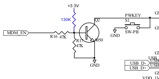
Mark, it seems we've got a hardware flaw here: EGPIO output port 0 (MDM_EN) is connected to transistor Q2 base via R16 without any pull-up. As the EGPIO ports are open drain, that can only work by chance. Maybe R16 was meant to be the pull-up, i.e. be connected to +3.3V, and MDM_EN should be connected directly to the transistor base?
I've verified this by checking the voltage level at MDM_EN & PWRKEY. When setting the port to 1, MDM_EN only rises for a very short time (too short for my multimeter to tell), and PWRKEY only drops very briefly. The modem needs PWRKEY low for at least 180ms to power up and at least 500ms to power down.
Manually pushing S1 reliably switches the modem on/off.
Maybe a fix for existing boards could be adding a pullup resistor at the transistor base?
I could try this if you suggest a value (and perhaps mark up a schematic?) Craig
Craig, Am 17.11.19 um 19:31 schrieb Craig Leres:
On 2019-11-17 04:11, Michael Balzer wrote:
I also saw this & can also reproduce this on my workbench. What is the method to induce the problem?
No method. If the theory is right it depends on a combination of random circumstances if the MDM_EN signal is long enough for the modem to recognize. I've got a module from the very first batch (3.0) and a 3.1 development module on my bench. The 3.0 module can power on/off the modem from port 0, the 3.1 cannot. It may also be related to some other condition, as I think the 3.1 module was able to control modem power at least once.
Maybe a fix for existing boards could be adding a pullup resistor at the transistor base? I could try this if you suggest a value (and perhaps mark up a schematic?)
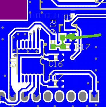
I think something in the range 130-150K should work. That should put the base to ~0.5-0.6V for low and to ~1.0-1.2V for high. That's either not fully switched off on low or not fully saturated on high, but should be sufficient for the modem. Schematic: PCB (down side): Regards, Michael -- Michael Balzer * Helkenberger Weg 9 * D-58256 Ennepetal Fon 02333 / 833 5735 * Handy 0176 / 206 989 26
Forgot: you can check if the pullup is working by monitoring the voltage level on the SIMCOM PWRKEY pin, that's pin 3. When MDM_EN is high the transistor should draw that to GND. Pin 3 is the third from the top on the left side (SIMCOM label wise). The driver puts MDM_EN to high for a whole second, so that should be clearly visible. Without the pullup, you should only see a very short pulse, if at all. Regards, Michael Am 17.11.19 um 22:29 schrieb Michael Balzer:
Craig,
Am 17.11.19 um 19:31 schrieb Craig Leres:
On 2019-11-17 04:11, Michael Balzer wrote:
I also saw this & can also reproduce this on my workbench. What is the method to induce the problem?
No method. If the theory is right it depends on a combination of random circumstances if the MDM_EN signal is long enough for the modem to recognize.
I've got a module from the very first batch (3.0) and a 3.1 development module on my bench. The 3.0 module can power on/off the modem from port 0, the 3.1 cannot. It may also be related to some other condition, as I think the 3.1 module was able to control modem power at least once.
Maybe a fix for existing boards could be adding a pullup resistor at the transistor base? I could try this if you suggest a value (and perhaps mark up a schematic?)
I think something in the range 130-150K should work. That should put the base to ~0.5-0.6V for low and to ~1.0-1.2V for high. That's either not fully switched off on low or not fully saturated on high, but should be sufficient for the modem.
Schematic:
PCB (down side):
Regards, Michael
-- Michael Balzer * Helkenberger Weg 9 * D-58256 Ennepetal Fon 02333 / 833 5735 * Handy 0176 / 206 989 26
_______________________________________________ OvmsDev mailing list OvmsDev@lists.openvehicles.com http://lists.openvehicles.com/mailman/listinfo/ovmsdev
-- Michael Balzer * Helkenberger Weg 9 * D-58256 Ennepetal Fon 02333 / 833 5735 * Handy 0176 / 206 989 26
On 2019-11-17 13:29, Michael Balzer wrote:
Craig,
Am 17.11.19 um 19:31 schrieb Craig Leres:
On 2019-11-17 04:11, Michael Balzer wrote:
I also saw this & can also reproduce this on my workbench. What is the method to induce the problem?
No method. If the theory is right it depends on a combination of random circumstances if the MDM_EN signal is long enough for the modem to recognize.
I guess I was hoping for a way to wedge the modem so I could be sure if the resistor works.
I think something in the range 130-150K should work. That should put the base to ~0.5-0.6V for low and to ~1.0-1.2V for high. That's either not fully switched off on low or not fully saturated on high, but should be sufficient for the modem.
Not 100% sure I have time left this weekend but when I try this I'll try to grab some traces with my scope. Also my collection of smd resistors is modest so I'll have to use 1/8w axial to test. Craig

I don’t think that circuit has changed since the very first v1 of OVMS. Maybe we have been lucky in the past with the timing? I will discuss it with the manufacturer, as that part of the circuit is his design and he should know the thinking behind it the best. Our intention it have EGPIO #0 able to control the PWRKEY of the modem - so as to be able to power it up/down under program control. We are not really controlling the power to the modem - more telling the modem to control itself. Regards, Mark.
On 17 Nov 2019, at 8:11 PM, Michael Balzer <dexter@expeedo.de> wrote:
I also saw this & can also reproduce this on my workbench.
Mark, it seems we've got a hardware flaw here: EGPIO output port 0 (MDM_EN) is connected to transistor Q2 base via R16 without any pull-up. As the EGPIO ports are open drain, that can only work by chance. Maybe R16 was meant to be the pull-up, i.e. be connected to +3.3V, and MDM_EN should be connected directly to the transistor base?
I've verified this by checking the voltage level at MDM_EN & PWRKEY. When setting the port to 1, MDM_EN only rises for a very short time (too short for my multimeter to tell), and PWRKEY only drops very briefly. The modem needs PWRKEY low for at least 180ms to power up and at least 500ms to power down.
Manually pushing S1 reliably switches the modem on/off.
Maybe a fix for existing boards could be adding a pullup resistor at the transistor base?
Regards, Michael
Am 17.11.19 um 02:39 schrieb Craig Leres:
Maybe this has been discussed and I missed it but occasionally I'll get a module with the modem/simcom stuck in the PoweringOn state. Rebooting does not fix this.
I thought I saw that you could reset the simcom with:
power simcom off [wait a minute] power simcom on
but that doesn't work. I turned up some logging:
log monitor log level verbose simcom
and I see this happen about every 30 seconds:
I (2204129) simcom: State timeout, transition to 2 I (2204129) simcom: State: Enter PoweringOn state I (2204129) simcom: Power Cycle
I thought this level of logging would let me see the results of command like:
simcom muxtx 3 at+csq
(signal quality) but I don't see anything after sending it.
Is there a way to hardware reset the simcom? (Is there any reason this doesn't happen when the ovms module reboots?)
Craig _______________________________________________ OvmsDev mailing list OvmsDev@lists.openvehicles.com http://lists.openvehicles.com/mailman/listinfo/ovmsdev
-- Michael Balzer * Helkenberger Weg 9 * D-58256 Ennepetal Fon 02333 / 833 5735 * Handy 0176 / 206 989 26
_______________________________________________ OvmsDev mailing list OvmsDev@lists.openvehicles.com http://lists.openvehicles.com/mailman/listinfo/ovmsdev
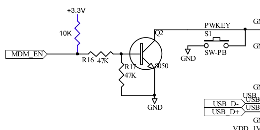
Craig, Mark, I just stumbled upon a misreading from my side: I had accidentally taken the v3.0 schematics of the main board for reference, that only had pull-ups on ports 1 & 2. There was a change in v3.1 adding pull-up resistors on ports 0 & 3 as well. So with a 3.1/3.2 module, there actually is a 10K pullup on both MDM_EN and MDM_DTR, before the transistor. With that 10K, we have this transistor control: That should result in ~1.5V at the base on MDM_EN high, enough for the transistor to switch, so I don't know what's going wrong here. You can access both pullups from the side, they are located left of the S2 switch on the main board. R8 is on MDM_EN, R9 on MDM_DTR. R8 shows that very short rise in voltage on transition to high, while R9 shows the expected behaviour of a constant +3.3 when the port is high. Regards, Michael Am 18.11.19 um 02:47 schrieb Mark Webb-Johnson:
I don’t think that circuit has changed since the very first v1 of OVMS. Maybe we have been lucky in the past with the timing?
I will discuss it with the manufacturer, as that part of the circuit is his design and he should know the thinking behind it the best.
Our intention it have EGPIO #0 able to control the PWRKEY of the modem - so as to be able to power it up/down under program control. We are not really controlling the power to the modem - more telling the modem to control itself.
Regards, Mark.
On 17 Nov 2019, at 8:11 PM, Michael Balzer <dexter@expeedo.de> wrote:
I also saw this & can also reproduce this on my workbench.
Mark, it seems we've got a hardware flaw here: EGPIO output port 0 (MDM_EN) is connected to transistor Q2 base via R16 without any pull-up. As the EGPIO ports are open drain, that can only work by chance. Maybe R16 was meant to be the pull-up, i.e. be connected to +3.3V, and MDM_EN should be connected directly to the transistor base?
I've verified this by checking the voltage level at MDM_EN & PWRKEY. When setting the port to 1, MDM_EN only rises for a very short time (too short for my multimeter to tell), and PWRKEY only drops very briefly. The modem needs PWRKEY low for at least 180ms to power up and at least 500ms to power down.
Manually pushing S1 reliably switches the modem on/off.
Maybe a fix for existing boards could be adding a pullup resistor at the transistor base?
Regards, Michael
Am 17.11.19 um 02:39 schrieb Craig Leres:
Maybe this has been discussed and I missed it but occasionally I'll get a module with the modem/simcom stuck in the PoweringOn state. Rebooting does not fix this.
I thought I saw that you could reset the simcom with:
power simcom off [wait a minute] power simcom on
but that doesn't work. I turned up some logging:
log monitor log level verbose simcom
and I see this happen about every 30 seconds:
I (2204129) simcom: State timeout, transition to 2 I (2204129) simcom: State: Enter PoweringOn state I (2204129) simcom: Power Cycle
I thought this level of logging would let me see the results of command like:
simcom muxtx 3 at+csq
(signal quality) but I don't see anything after sending it.
Is there a way to hardware reset the simcom? (Is there any reason this doesn't happen when the ovms module reboots?)
Craig _______________________________________________ OvmsDev mailing list OvmsDev@lists.openvehicles.com http://lists.openvehicles.com/mailman/listinfo/ovmsdev -- Michael Balzer * Helkenberger Weg 9 * D-58256 Ennepetal Fon 02333 / 833 5735 * Handy 0176 / 206 989 26
_______________________________________________ OvmsDev mailing list OvmsDev@lists.openvehicles.com http://lists.openvehicles.com/mailman/listinfo/ovmsdev
OvmsDev mailing list OvmsDev@lists.openvehicles.com http://lists.openvehicles.com/mailman/listinfo/ovmsdev
-- Michael Balzer * Helkenberger Weg 9 * D-58256 Ennepetal Fon 02333 / 833 5735 * Handy 0176 / 206 989 26
That makes more sense. I have passed on the information to the manufacturer, as he is best placed to check what is going on. I suggested to him that he can recreate the issue by powering off the SIMCOM (or not powering it on in the first place) and then using 'egpio output 0 0’ and 'egpio output 0 1’ to test. He should be able to give us a reply later this week. Regards, Mark.
On 18 Nov 2019, at 11:13 PM, Michael Balzer <dexter@expeedo.de> wrote:
Craig, Mark,
I just stumbled upon a misreading from my side:
I had accidentally taken the v3.0 schematics of the main board for reference, that only had pull-ups on ports 1 & 2. There was a change in v3.1 adding pull-up resistors on ports 0 & 3 as well.
So with a 3.1/3.2 module, there actually is a 10K pullup on both MDM_EN and MDM_DTR, before the transistor.
With that 10K, we have this transistor control: <ojgbfmjianhnlmjd.png>
That should result in ~1.5V at the base on MDM_EN high, enough for the transistor to switch, so I don't know what's going wrong here.
You can access both pullups from the side, they are located left of the S2 switch on the main board. R8 is on MDM_EN, R9 on MDM_DTR. R8 shows that very short rise in voltage on transition to high, while R9 shows the expected behaviour of a constant +3.3 when the port is high.
Regards, Michael
Am 18.11.19 um 02:47 schrieb Mark Webb-Johnson:
I don’t think that circuit has changed since the very first v1 of OVMS. Maybe we have been lucky in the past with the timing?
I will discuss it with the manufacturer, as that part of the circuit is his design and he should know the thinking behind it the best.
Our intention it have EGPIO #0 able to control the PWRKEY of the modem - so as to be able to power it up/down under program control. We are not really controlling the power to the modem - more telling the modem to control itself.
Regards, Mark.
On 17 Nov 2019, at 8:11 PM, Michael Balzer <dexter@expeedo.de> <mailto:dexter@expeedo.de> wrote:
I also saw this & can also reproduce this on my workbench.
Mark, it seems we've got a hardware flaw here: EGPIO output port 0 (MDM_EN) is connected to transistor Q2 base via R16 without any pull-up. As the EGPIO ports are open drain, that can only work by chance. Maybe R16 was meant to be the pull-up, i.e. be connected to +3.3V, and MDM_EN should be connected directly to the transistor base?
I've verified this by checking the voltage level at MDM_EN & PWRKEY. When setting the port to 1, MDM_EN only rises for a very short time (too short for my multimeter to tell), and PWRKEY only drops very briefly. The modem needs PWRKEY low for at least 180ms to power up and at least 500ms to power down.
Manually pushing S1 reliably switches the modem on/off.
Maybe a fix for existing boards could be adding a pullup resistor at the transistor base?
Regards, Michael
Am 17.11.19 um 02:39 schrieb Craig Leres:
Maybe this has been discussed and I missed it but occasionally I'll get a module with the modem/simcom stuck in the PoweringOn state. Rebooting does not fix this.
I thought I saw that you could reset the simcom with:
power simcom off [wait a minute] power simcom on
but that doesn't work. I turned up some logging:
log monitor log level verbose simcom
and I see this happen about every 30 seconds:
I (2204129) simcom: State timeout, transition to 2 I (2204129) simcom: State: Enter PoweringOn state I (2204129) simcom: Power Cycle
I thought this level of logging would let me see the results of command like:
simcom muxtx 3 at+csq
(signal quality) but I don't see anything after sending it.
Is there a way to hardware reset the simcom? (Is there any reason this doesn't happen when the ovms module reboots?)
Craig _______________________________________________ OvmsDev mailing list OvmsDev@lists.openvehicles.com <mailto:OvmsDev@lists.openvehicles.com> http://lists.openvehicles.com/mailman/listinfo/ovmsdev <http://lists.openvehicles.com/mailman/listinfo/ovmsdev> -- Michael Balzer * Helkenberger Weg 9 * D-58256 Ennepetal Fon 02333 / 833 5735 * Handy 0176 / 206 989 26
_______________________________________________ OvmsDev mailing list OvmsDev@lists.openvehicles.com <mailto:OvmsDev@lists.openvehicles.com> http://lists.openvehicles.com/mailman/listinfo/ovmsdev <http://lists.openvehicles.com/mailman/listinfo/ovmsdev>
OvmsDev mailing list OvmsDev@lists.openvehicles.com <mailto:OvmsDev@lists.openvehicles.com> http://lists.openvehicles.com/mailman/listinfo/ovmsdev <http://lists.openvehicles.com/mailman/listinfo/ovmsdev>
-- Michael Balzer * Helkenberger Weg 9 * D-58256 Ennepetal Fon 02333 / 833 5735 * Handy 0176 / 206 989 26 _______________________________________________ OvmsDev mailing list OvmsDev@lists.openvehicles.com http://lists.openvehicles.com/mailman/listinfo/ovmsdev
Michael, The manufacturer is having problems repeating the problem. He is looking at the voltage on MDM_EN when toggling EGPIO #0, using the v3.2 hardware, and says it switches properly for him. I did a quick check with some 3.1 hardware, and it seems ok for me as well (although I only used a multi-meter, not an oscilloscope). Can you confirm what version of board (main board and modem) that you are using to recreate this problem? Also version of firmware and that the new egpio monitor feature is off (in case that is interfering in some way)? Regards, Mark
On 19 Nov 2019, at 9:36 AM, Mark Webb-Johnson <mark@webb-johnson.net> wrote:
That makes more sense.
I have passed on the information to the manufacturer, as he is best placed to check what is going on. I suggested to him that he can recreate the issue by powering off the SIMCOM (or not powering it on in the first place) and then using 'egpio output 0 0’ and 'egpio output 0 1’ to test. He should be able to give us a reply later this week.
Regards, Mark.
On 18 Nov 2019, at 11:13 PM, Michael Balzer <dexter@expeedo.de <mailto:dexter@expeedo.de>> wrote:
Craig, Mark,
I just stumbled upon a misreading from my side:
I had accidentally taken the v3.0 schematics of the main board for reference, that only had pull-ups on ports 1 & 2. There was a change in v3.1 adding pull-up resistors on ports 0 & 3 as well.
So with a 3.1/3.2 module, there actually is a 10K pullup on both MDM_EN and MDM_DTR, before the transistor.
With that 10K, we have this transistor control: <ojgbfmjianhnlmjd.png>
That should result in ~1.5V at the base on MDM_EN high, enough for the transistor to switch, so I don't know what's going wrong here.
You can access both pullups from the side, they are located left of the S2 switch on the main board. R8 is on MDM_EN, R9 on MDM_DTR. R8 shows that very short rise in voltage on transition to high, while R9 shows the expected behaviour of a constant +3.3 when the port is high.
Regards, Michael
Am 18.11.19 um 02:47 schrieb Mark Webb-Johnson:
I don’t think that circuit has changed since the very first v1 of OVMS. Maybe we have been lucky in the past with the timing?
I will discuss it with the manufacturer, as that part of the circuit is his design and he should know the thinking behind it the best.
Our intention it have EGPIO #0 able to control the PWRKEY of the modem - so as to be able to power it up/down under program control. We are not really controlling the power to the modem - more telling the modem to control itself.
Regards, Mark.
On 17 Nov 2019, at 8:11 PM, Michael Balzer <dexter@expeedo.de> <mailto:dexter@expeedo.de> wrote:
I also saw this & can also reproduce this on my workbench.
Mark, it seems we've got a hardware flaw here: EGPIO output port 0 (MDM_EN) is connected to transistor Q2 base via R16 without any pull-up. As the EGPIO ports are open drain, that can only work by chance. Maybe R16 was meant to be the pull-up, i.e. be connected to +3.3V, and MDM_EN should be connected directly to the transistor base?
I've verified this by checking the voltage level at MDM_EN & PWRKEY. When setting the port to 1, MDM_EN only rises for a very short time (too short for my multimeter to tell), and PWRKEY only drops very briefly. The modem needs PWRKEY low for at least 180ms to power up and at least 500ms to power down.
Manually pushing S1 reliably switches the modem on/off.
Maybe a fix for existing boards could be adding a pullup resistor at the transistor base?
Regards, Michael
Am 17.11.19 um 02:39 schrieb Craig Leres:
Maybe this has been discussed and I missed it but occasionally I'll get a module with the modem/simcom stuck in the PoweringOn state. Rebooting does not fix this.
I thought I saw that you could reset the simcom with:
power simcom off [wait a minute] power simcom on
but that doesn't work. I turned up some logging:
log monitor log level verbose simcom
and I see this happen about every 30 seconds:
I (2204129) simcom: State timeout, transition to 2 I (2204129) simcom: State: Enter PoweringOn state I (2204129) simcom: Power Cycle
I thought this level of logging would let me see the results of command like:
simcom muxtx 3 at+csq
(signal quality) but I don't see anything after sending it.
Is there a way to hardware reset the simcom? (Is there any reason this doesn't happen when the ovms module reboots?)
Craig _______________________________________________ OvmsDev mailing list OvmsDev@lists.openvehicles.com <mailto:OvmsDev@lists.openvehicles.com> http://lists.openvehicles.com/mailman/listinfo/ovmsdev <http://lists.openvehicles.com/mailman/listinfo/ovmsdev> -- Michael Balzer * Helkenberger Weg 9 * D-58256 Ennepetal Fon 02333 / 833 5735 * Handy 0176 / 206 989 26
_______________________________________________ OvmsDev mailing list OvmsDev@lists.openvehicles.com <mailto:OvmsDev@lists.openvehicles.com> http://lists.openvehicles.com/mailman/listinfo/ovmsdev <http://lists.openvehicles.com/mailman/listinfo/ovmsdev>
OvmsDev mailing list OvmsDev@lists.openvehicles.com <mailto:OvmsDev@lists.openvehicles.com> http://lists.openvehicles.com/mailman/listinfo/ovmsdev <http://lists.openvehicles.com/mailman/listinfo/ovmsdev>
-- Michael Balzer * Helkenberger Weg 9 * D-58256 Ennepetal Fon 02333 / 833 5735 * Handy 0176 / 206 989 26 _______________________________________________ OvmsDev mailing list OvmsDev@lists.openvehicles.com <mailto:OvmsDev@lists.openvehicles.com> http://lists.openvehicles.com/mailman/listinfo/ovmsdev
_______________________________________________ OvmsDev mailing list OvmsDev@lists.openvehicles.com http://lists.openvehicles.com/mailman/listinfo/ovmsdev
Shame on me. Reminder: expect the unexpected. The egpio monitor actually caused this. Or more precisely, the MAX7317 input query, which was broken in a remarkable way. Explanation: The MAX7317 needs a deselect between addressing a register for read and reading the value returned. On the second SPI command to read the value, no TX was requested, just the two bytes RX. But on SPI, there is no "no TX". An SPI transaction always is TX and RX in parallel. Doing a 0 byte TX + 2 byte RX SPI command via our SPI API actually means you'll be doing a TX of two zero bytes to the device while reading two bytes from the device. And if you send two zero bytes to the MAX7317, it will interpret that as "set output port 0 to level 0"… While that's totally clear from the datasheet: in my humble opinion, requiring separate request & response transactions and then assigning a command to a sequence of all zero bytes is bad design. NOP on the MAX7317 is 0x20, so I've changed the input query to send that while receiving the result. Thanks, Mark. Back to the original issue: Input monitoring is disabled by default. Craig, you reported not being able to power down the modem 2 hours after I pushed the egpio monitoring. Did you have the issue with input monitoring enabled? If not, the issue still needs to be resolved. Regards, Michael Am 21.11.19 um 00:57 schrieb Mark Webb-Johnson:
Michael,
The manufacturer is having problems repeating the problem. He is looking at the voltage on MDM_EN when toggling EGPIO #0, using the v3.2 hardware, and says it switches properly for him. I did a quick check with some 3.1 hardware, and it seems ok for me as well (although I only used a multi-meter, not an oscilloscope).
Can you confirm what version of board (main board and modem) that you are using to recreate this problem? Also version of firmware and that the new egpio monitor feature is off (in case that is interfering in some way)?
Regards, Mark
On 19 Nov 2019, at 9:36 AM, Mark Webb-Johnson <mark@webb-johnson.net <mailto:mark@webb-johnson.net>> wrote:
That makes more sense.
I have passed on the information to the manufacturer, as he is best placed to check what is going on. I suggested to him that he can recreate the issue by powering off the SIMCOM (or not powering it on in the first place) and then using 'egpio output 0 0’ and 'egpio output 0 1’ to test. He should be able to give us a reply later this week.
Regards, Mark.
On 18 Nov 2019, at 11:13 PM, Michael Balzer <dexter@expeedo.de <mailto:dexter@expeedo.de>> wrote:
Craig, Mark,
I just stumbled upon a misreading from my side:
I had accidentally taken the v3.0 schematics of the main board for reference, that only had pull-ups on ports 1 & 2. There was a change in v3.1 adding pull-up resistors on ports 0 & 3 as well.
So with a 3.1/3.2 module, there actually is a 10K pullup on both MDM_EN and MDM_DTR, before the transistor.
With that 10K, we have this transistor control: <ojgbfmjianhnlmjd.png>
That should result in ~1.5V at the base on MDM_EN high, enough for the transistor to switch, so I don't know what's going wrong here.
You can access both pullups from the side, they are located left of the S2 switch on the main board. R8 is on MDM_EN, R9 on MDM_DTR. R8 shows that very short rise in voltage on transition to high, while R9 shows the expected behaviour of a constant +3.3 when the port is high.
Regards, Michael
Am 18.11.19 um 02:47 schrieb Mark Webb-Johnson:
I don’t think that circuit has changed since the very first v1 of OVMS. Maybe we have been lucky in the past with the timing?
I will discuss it with the manufacturer, as that part of the circuit is his design and he should know the thinking behind it the best.
Our intention it have EGPIO #0 able to control the PWRKEY of the modem - so as to be able to power it up/down under program control. We are not really controlling the power to the modem - more telling the modem to control itself.
Regards, Mark.
On 17 Nov 2019, at 8:11 PM, Michael Balzer <dexter@expeedo.de> wrote:
I also saw this & can also reproduce this on my workbench.
Mark, it seems we've got a hardware flaw here: EGPIO output port 0 (MDM_EN) is connected to transistor Q2 base via R16 without any pull-up. As the EGPIO ports are open drain, that can only work by chance. Maybe R16 was meant to be the pull-up, i.e. be connected to +3.3V, and MDM_EN should be connected directly to the transistor base?
I've verified this by checking the voltage level at MDM_EN & PWRKEY. When setting the port to 1, MDM_EN only rises for a very short time (too short for my multimeter to tell), and PWRKEY only drops very briefly. The modem needs PWRKEY low for at least 180ms to power up and at least 500ms to power down.
Manually pushing S1 reliably switches the modem on/off.
Maybe a fix for existing boards could be adding a pullup resistor at the transistor base?
Regards, Michael
Am 17.11.19 um 02:39 schrieb Craig Leres:
Maybe this has been discussed and I missed it but occasionally I'll get a module with the modem/simcom stuck in the PoweringOn state. Rebooting does not fix this.
I thought I saw that you could reset the simcom with:
power simcom off [wait a minute] power simcom on
but that doesn't work. I turned up some logging:
log monitor log level verbose simcom
and I see this happen about every 30 seconds:
I (2204129) simcom: State timeout, transition to 2 I (2204129) simcom: State: Enter PoweringOn state I (2204129) simcom: Power Cycle
I thought this level of logging would let me see the results of command like:
simcom muxtx 3 at+csq
(signal quality) but I don't see anything after sending it.
Is there a way to hardware reset the simcom? (Is there any reason this doesn't happen when the ovms module reboots?)
Craig _______________________________________________ OvmsDev mailing list OvmsDev@lists.openvehicles.com http://lists.openvehicles.com/mailman/listinfo/ovmsdev -- Michael Balzer * Helkenberger Weg 9 * D-58256 Ennepetal Fon 02333 / 833 5735 * Handy 0176 / 206 989 26
_______________________________________________ OvmsDev mailing list OvmsDev@lists.openvehicles.com http://lists.openvehicles.com/mailman/listinfo/ovmsdev
OvmsDev mailing list OvmsDev@lists.openvehicles.com http://lists.openvehicles.com/mailman/listinfo/ovmsdev
-- Michael Balzer * Helkenberger Weg 9 * D-58256 Ennepetal Fon 02333 / 833 5735 * Handy 0176 / 206 989 26 _______________________________________________ OvmsDev mailing list OvmsDev@lists.openvehicles.com <mailto:OvmsDev@lists.openvehicles.com> http://lists.openvehicles.com/mailman/listinfo/ovmsdev
_______________________________________________ OvmsDev mailing list OvmsDev@lists.openvehicles.com <mailto:OvmsDev@lists.openvehicles.com> http://lists.openvehicles.com/mailman/listinfo/ovmsdev
_______________________________________________ OvmsDev mailing list OvmsDev@lists.openvehicles.com http://lists.openvehicles.com/mailman/listinfo/ovmsdev
-- Michael Balzer * Helkenberger Weg 9 * D-58256 Ennepetal Fon 02333 / 833 5735 * Handy 0176 / 206 989 26
I’m just glad it wasn’t a hardware issue. I checked through my mails, and found we did spend quite some time on this with the guys in China when we did the final prototypes for v3.1; everything looked very stable back then. Thanks for the feedback, and working through this problem. Hopefully the issue Craig reported, I hope it is either v3.0 dev hardware (pre pull-up) or something else. Regards, Mark.
On 21 Nov 2019, at 5:46 PM, Michael Balzer <dexter@expeedo.de> wrote:
Shame on me. Reminder: expect the unexpected.
The egpio monitor actually caused this. Or more precisely, the MAX7317 input query, which was broken in a remarkable way.
Explanation:
The MAX7317 needs a deselect between addressing a register for read and reading the value returned. On the second SPI command to read the value, no TX was requested, just the two bytes RX.
But on SPI, there is no "no TX". An SPI transaction always is TX and RX in parallel. Doing a 0 byte TX + 2 byte RX SPI command via our SPI API actually means you'll be doing a TX of two zero bytes to the device while reading two bytes from the device.
And if you send two zero bytes to the MAX7317, it will interpret that as "set output port 0 to level 0"…
While that's totally clear from the datasheet: in my humble opinion, requiring separate request & response transactions and then assigning a command to a sequence of all zero bytes is bad design.
NOP on the MAX7317 is 0x20, so I've changed the input query to send that while receiving the result.
Thanks, Mark.
Back to the original issue: Input monitoring is disabled by default. Craig, you reported not being able to power down the modem 2 hours after I pushed the egpio monitoring. Did you have the issue with input monitoring enabled? If not, the issue still needs to be resolved.
Regards, Michael
Am 21.11.19 um 00:57 schrieb Mark Webb-Johnson:
Michael,
The manufacturer is having problems repeating the problem. He is looking at the voltage on MDM_EN when toggling EGPIO #0, using the v3.2 hardware, and says it switches properly for him. I did a quick check with some 3.1 hardware, and it seems ok for me as well (although I only used a multi-meter, not an oscilloscope).
Can you confirm what version of board (main board and modem) that you are using to recreate this problem? Also version of firmware and that the new egpio monitor feature is off (in case that is interfering in some way)?
Regards, Mark
On 19 Nov 2019, at 9:36 AM, Mark Webb-Johnson <mark@webb-johnson.net <mailto:mark@webb-johnson.net>> wrote:
That makes more sense.
I have passed on the information to the manufacturer, as he is best placed to check what is going on. I suggested to him that he can recreate the issue by powering off the SIMCOM (or not powering it on in the first place) and then using 'egpio output 0 0’ and 'egpio output 0 1’ to test. He should be able to give us a reply later this week.
Regards, Mark.
On 18 Nov 2019, at 11:13 PM, Michael Balzer <dexter@expeedo.de <mailto:dexter@expeedo.de>> wrote:
Craig, Mark,
I just stumbled upon a misreading from my side:
I had accidentally taken the v3.0 schematics of the main board for reference, that only had pull-ups on ports 1 & 2. There was a change in v3.1 adding pull-up resistors on ports 0 & 3 as well.
So with a 3.1/3.2 module, there actually is a 10K pullup on both MDM_EN and MDM_DTR, before the transistor.
With that 10K, we have this transistor control: <ojgbfmjianhnlmjd.png>
That should result in ~1.5V at the base on MDM_EN high, enough for the transistor to switch, so I don't know what's going wrong here.
You can access both pullups from the side, they are located left of the S2 switch on the main board. R8 is on MDM_EN, R9 on MDM_DTR. R8 shows that very short rise in voltage on transition to high, while R9 shows the expected behaviour of a constant +3.3 when the port is high.
Regards, Michael
Am 18.11.19 um 02:47 schrieb Mark Webb-Johnson:
I don’t think that circuit has changed since the very first v1 of OVMS. Maybe we have been lucky in the past with the timing?
I will discuss it with the manufacturer, as that part of the circuit is his design and he should know the thinking behind it the best.
Our intention it have EGPIO #0 able to control the PWRKEY of the modem - so as to be able to power it up/down under program control. We are not really controlling the power to the modem - more telling the modem to control itself.
Regards, Mark.
On 17 Nov 2019, at 8:11 PM, Michael Balzer <dexter@expeedo.de> <mailto:dexter@expeedo.de> wrote:
I also saw this & can also reproduce this on my workbench.
Mark, it seems we've got a hardware flaw here: EGPIO output port 0 (MDM_EN) is connected to transistor Q2 base via R16 without any pull-up. As the EGPIO ports are open drain, that can only work by chance. Maybe R16 was meant to be the pull-up, i.e. be connected to +3.3V, and MDM_EN should be connected directly to the transistor base?
I've verified this by checking the voltage level at MDM_EN & PWRKEY. When setting the port to 1, MDM_EN only rises for a very short time (too short for my multimeter to tell), and PWRKEY only drops very briefly. The modem needs PWRKEY low for at least 180ms to power up and at least 500ms to power down.
Manually pushing S1 reliably switches the modem on/off.
Maybe a fix for existing boards could be adding a pullup resistor at the transistor base?
Regards, Michael
Am 17.11.19 um 02:39 schrieb Craig Leres: > Maybe this has been discussed and I missed it but occasionally I'll get a module with the modem/simcom stuck in the PoweringOn state. Rebooting does not fix > this. > > I thought I saw that you could reset the simcom with: > > power simcom off > [wait a minute] > power simcom on > > but that doesn't work. I turned up some logging: > > log monitor > log level verbose simcom > > and I see this happen about every 30 seconds: > > I (2204129) simcom: State timeout, transition to 2 > I (2204129) simcom: State: Enter PoweringOn state > I (2204129) simcom: Power Cycle > > I thought this level of logging would let me see the results of command like: > > simcom muxtx 3 at+csq > > (signal quality) but I don't see anything after sending it. > > Is there a way to hardware reset the simcom? (Is there any reason this doesn't happen when the ovms module reboots?) > > Craig > _______________________________________________ > OvmsDev mailing list > OvmsDev@lists.openvehicles.com <mailto:OvmsDev@lists.openvehicles.com> > http://lists.openvehicles.com/mailman/listinfo/ovmsdev <http://lists.openvehicles.com/mailman/listinfo/ovmsdev> -- Michael Balzer * Helkenberger Weg 9 * D-58256 Ennepetal Fon 02333 / 833 5735 * Handy 0176 / 206 989 26
_______________________________________________ OvmsDev mailing list OvmsDev@lists.openvehicles.com <mailto:OvmsDev@lists.openvehicles.com> http://lists.openvehicles.com/mailman/listinfo/ovmsdev <http://lists.openvehicles.com/mailman/listinfo/ovmsdev>
OvmsDev mailing list OvmsDev@lists.openvehicles.com <mailto:OvmsDev@lists.openvehicles.com> http://lists.openvehicles.com/mailman/listinfo/ovmsdev <http://lists.openvehicles.com/mailman/listinfo/ovmsdev>
-- Michael Balzer * Helkenberger Weg 9 * D-58256 Ennepetal Fon 02333 / 833 5735 * Handy 0176 / 206 989 26 _______________________________________________ OvmsDev mailing list OvmsDev@lists.openvehicles.com <mailto:OvmsDev@lists.openvehicles.com> http://lists.openvehicles.com/mailman/listinfo/ovmsdev <http://lists.openvehicles.com/mailman/listinfo/ovmsdev>
_______________________________________________ OvmsDev mailing list OvmsDev@lists.openvehicles.com <mailto:OvmsDev@lists.openvehicles.com> http://lists.openvehicles.com/mailman/listinfo/ovmsdev <http://lists.openvehicles.com/mailman/listinfo/ovmsdev>
_______________________________________________ OvmsDev mailing list OvmsDev@lists.openvehicles.com <mailto:OvmsDev@lists.openvehicles.com> http://lists.openvehicles.com/mailman/listinfo/ovmsdev <http://lists.openvehicles.com/mailman/listinfo/ovmsdev>
-- Michael Balzer * Helkenberger Weg 9 * D-58256 Ennepetal Fon 02333 / 833 5735 * Handy 0176 / 206 989 26 _______________________________________________ OvmsDev mailing list OvmsDev@lists.openvehicles.com http://lists.openvehicles.com/mailman/listinfo/ovmsdev
On 2019-11-21 01:46, Michael Balzer wrote:
Shame on me. Reminder: expect the unexpected.
The egpio monitor actually caused this. Or more precisely, the MAX7317 input query, which was broken in a remarkable way.
Explanation:
The MAX7317 needs a deselect between addressing a register for read and reading the value returned. On the second SPI command to read the value, no TX was requested, just the two bytes RX.
But on SPI, there is no "no TX". An SPI transaction always is TX and RX in parallel. Doing a 0 byte TX + 2 byte RX SPI command via our SPI API actually means you'll be doing a TX of two zero bytes to the device while reading two bytes from the device.
And if you send two zero bytes to the MAX7317, it will interpret that as "set output port 0 to level 0"…
While that's totally clear from the datasheet: in my humble opinion, requiring separate request & response transactions and then assigning a command to a sequence of all zero bytes is bad design.
NOP on the MAX7317 is 0x20, so I've changed the input query to send that while receiving the result.
Thanks, Mark.
Back to the original issue: Input monitoring is disabled by default. Craig, you reported not being able to power down the modem 2 hours after I pushed the egpio monitoring. Did you have the issue with input monitoring enabled? If not, the issue still needs to be resolved.
I don't think the egpio monitor code is involved with my issue. The specific module I had the simcom wedge is the first one I bought (March 2018) and my receipt shows it's v3.1. I've seen this problem a number of times and had meant to collect some info and report it. I started this thread on Nov 16th. Looking at my server logs I think I was running 3.2.005-105-g9af31240-dirty (downloaded by that module on Nov 7th). Later that day (probably while trying to clear the problem with actually removing power from the module) I also booted 3.2.005-107-g350f5f10-dirty. I don't think the MAX7317 stuff got added until Nov 17 so I don't think there's any way I was running it. As I understand it, there is no control over simcom power just control of an input to simcom that requests that it powers off (or on). So is the problem that it's possible to wedge the simcom in such a way that it ignores the control input? Craig
Am 22.11.19 um 07:25 schrieb Craig Leres:
As I understand it, there is no control over simcom power just control of an input to simcom that requests that it powers off (or on). So is the problem that it's possible to wedge the simcom in such a way that it ignores the control input?
Most likely. What firmware version do you have on the SIMCOM? We've found differences in bug behaviour already: https://github.com/openvehicles/Open-Vehicle-Monitoring-System-3/issues/284#... My modules have: * v3.0 module, modem board v1.0: 35316*B10*SIM5360E * older v3.1 module, modem board v1.1: 35316*B11*SIM5360E * newer v3.1 module, modem board v1.1: 35316*B09*SIM5360E I don't have a 3.2 module or US modems to check. Interestingly, the B11 version for the 5360E isn't even downloadable at SIMCOM: https://simcom.ee/documents/?dir=SIM5360 I've found later versions (up to B13) and release notes listed only here: https://techship.com/products/simcom-sim5360e-mpcie-sim/ …but you need an account to access them and must accept an NDA. Regards, Michael -- Michael Balzer * Helkenberger Weg 9 * D-58256 Ennepetal Fon 02333 / 833 5735 * Handy 0176 / 206 989 26
On 2019-11-22 01:56, Michael Balzer wrote:
What firmware version do you have on the SIMCOM?
The one that most recently wedged is... wedged again: OVMS# simcom cmd AT+CGMR ERROR: SIMCOM command channel not available! But in a new way, the gps is working and the modem is registered with the network: OVMS# simcom Network Registration: RegisteredRoaming Provider: T-Mobile Hologram Signal: -93 dBm State: PoweringOn PPP: Not connected Last Error: User Interrupt GPS: Not connected I guess it got into a funny state when I was driving earlier. Anyway after rebooting it was still stuck in PoweringOn so I cycled power. Ok, both of the modules I have in cars are 35316B07SIM5360A. My third module is the one I swapped simcoms in and is LE11B02SIM7500A (physical label says 7600A). I registered with techship.com and have the firmware update tool. But the only rar files I see look like they're for the European SIM5360? https://simcom.ee/documents/?dir=SIM5360 35316B09SIM5360E.rar 35316B10SIM5360E.rar 35316B10SIM5360E_QDL5.1.rar and I don't see anything for the 7600. I've asked if the US firmware is available. What's the path to upgrading simcom firmware? Is it just a matter of plugging the usb connector on the modem board to my windows 10 laptop? I can see USB_D- and USB_D+ connections to the simcom, not sure about USB_5V. Tomorrow I'll try to pull my car modules and determine if the modem boards have the pullup resistor or not. One last thing I'm confused about is the pullup resistor on the MEM_EN line. I don't see it on v3.1 or v3.2 schematics? I tried to complare the pdfs from github visually and the only difference I see is in the A0Z1280CI circuit (and I remember Mark saying they added a choke to the power supply). Craig
Am 22.11.19 um 10:56 schrieb Michael Balzer:
Am 22.11.19 um 07:25 schrieb Craig Leres:
As I understand it, there is no control over simcom power just control of an input to simcom that requests that it powers off (or on). So is the problem that it's possible to wedge the simcom in such a way that it ignores the control input?
Most likely.
… IF you've verified the modem really ignores the power down signal. You cannot do so only by watching the OVMS log, as the UART RX may also be lost somehow. You need to check the blue LED on the modem board. If it's a UART issue, the OVMS cannot detect any modem response and will also loop in the power up states.
On 2019-11-22 01:56, Michael Balzer wrote:
What firmware version do you have on the SIMCOM?
The one that most recently wedged is... wedged again:
OVMS# simcom cmd AT+CGMR ERROR: SIMCOM command channel not available!
That may be a MUX state bug, or you may have hit the time between MUX init and established channels. See simcom::txcmd().
But in a new way, the gps is working and the modem is registered with the network:
PPP: Not connected Last Error: User Interrupt
"User Interrupt" triggers me… I had this a few days ago during the night (with wifi network in use), the module needed a reboot to recover: 2019-11-19 04:05:14 CET I (40641522) simcom: PPP Connection disconnected 2019-11-19 04:05:15 CET I (40642022) simcom: Lost network connection (+PPP disconnect in NetMode) 2019-11-19 04:05:15 CET I (40642022) simcom: State: Enter NetLoss state 2019-11-19 04:05:15 CET I (40642032) gsm-ppp: Shutting down (hard)... 2019-11-19 04:05:15 CET I (40642032) gsm-ppp: PPP is shutdown 2019-11-19 04:05:15 CET D (40642062) events: Signal(system.modem.netloss) 2019-11-19 04:05:15 CET D (40642102) events: Signal(system.modem.down) 2019-11-19 04:05:15 CET I (40642102) netmanager: Set DNS#2 0.0.0.0 2019-11-19 04:05:15 CET I (40642112) netmanager: MODEM down (with WIFI client up): staying with WIFI client priority 2019-11-19 04:05:15 CET D (40642152) events: Signal(network.modem.down) 2019-11-19 04:05:15 CET D (40642192) events: Signal(network.interface.change) 2019-11-19 04:05:20 CET I (40647522) gsm-ppp: StatusCallBack: *User Interrupt* 2019-11-19 04:05:20 CET I (40647522) gsm-ppp: PPP connection has been closed 2019-11-19 04:05:20 CET D (40647532) events: Signal(system.modem.down) 2019-11-19 04:05:20 CET I (40647532) netmanager: Set DNS#2 0.0.0.0 2019-11-19 04:05:15 CET I (40651022) simcom: State timeout, transition to 5 2019-11-19 04:05:15 CET I (40651022) simcom: State: Enter NetWait state 2019-11-19 04:05:15 CET I (40651022) gsm-nmea: Startup 2019-11-19 04:05:15 CET D (40651092) events: Signal(system.modem.netwait) 2019-11-19 04:05:27 CET I (40655022) simcom: State: Enter NetStart state 2019-11-19 04:05:27 CET D (40655062) events: Signal(system.modem.netstart) 2019-11-19 04:05:56 CET I (40684022) simcom: State timeout, transition to 14 2019-11-19 04:05:57 CET I (40684022) simcom: State: Enter PowerOffOn state 2019-11-19 04:05:57 CET I (40684022) gsm-ppp: Shutting down (soft)... 2019-11-19 04:05:57 CET I (40684022) gsm-ppp: StatusCallBack: *User Interrupt* 2019-11-19 04:05:57 CET I (40684022) gsm-ppp: PPP connection has been closed 2019-11-19 04:05:57 CET I (40684032) gsm-ppp: PPP is shutdown 2019-11-19 04:05:57 CET I (40684032) gsm-nmea: Shutdown (direct) 2019-11-19 04:05:57 CET I (40684042) gsm-mux: Stop MUX 2019-11-19 04:05:57 CET I (40684052) simcom: Power Cycle 2019-11-19 04:05:58 CET D (40685102) events: Signal(system.modem.down) 2019-11-19 04:05:58 CET I (40685102) netmanager: Set DNS#2 0.0.0.0 2019-11-19 04:05:58 CET D (40685142) events: Signal(system.modem.down) 2019-11-19 04:05:58 CET I (40685142) netmanager: Set DNS#2 0.0.0.0 2019-11-19 04:05:58 CET D (40685162) events: Signal(gps.lock.lost) 2019-11-19 04:05:58 CET D (40685192) events: Signal(system.modem.lostgps) 2019-11-19 04:05:58 CET D (40685222) events: Signal(system.modem.stop) 2019-11-19 04:05:58 CET I (40685222) netmanager: Set DNS#2 0.0.0.0 2019-11-19 04:05:58 CET D (40685262) events: Signal(egpio.output.0.high) 2019-11-19 04:05:58 CET D (40685322) events: Signal(egpio.output.0.low) 2019-11-19 04:05:59 CET I (40687022) simcom: State timeout, transition to 2 2019-11-19 04:06:00 CET I (40687022) simcom: State: Enter PoweringOn state 2019-11-19 04:06:00 CET I (40687022) simcom: Power Cycle … looping from here in power up until reboot … I haven't found documentation on PPPERR_USER.
Ok, both of the modules I have in cars are 35316B07SIM5360A. My third module is the one I swapped simcoms in and is LE11B02SIM7500A (physical label says 7600A).
I registered with techship.com and have the firmware update tool. But the only rar files I see look like they're for the European SIM5360?
They only seem to have the E version. There are some other directories on simcom.ee, but no firmware for you it seems. Maybe we need to ask SIMCOM to provide updates? But it also doesn't look like there's some documented issue with the modem being stuck ignoring PWRKEY. I'd first look for bugs on our side.
Tomorrow I'll try to pull my car modules and determine if the modem boards have the pullup resistor or not.
One last thing I'm confused about is the pullup resistor on the MEM_EN line. I don't see it on v3.1 or v3.2 schematics? I tried to complare the pdfs from github visually and the only difference I see is in the A0Z1280CI circuit (and I remember Mark saying they added a choke to the power supply).
It's on the main board, at the MAX7317. Regards, Michael -- Michael Balzer * Helkenberger Weg 9 * D-58256 Ennepetal Fon 02333 / 833 5735 * Handy 0176 / 206 989 26
Craig, This is the line that matters: State: PoweringOn The others all show the status before the last power down. That state means it is sending OK’s to the modem, and waiting for a response. If it doesn’t get one, it will try a reset (via MDM_EN) and wait again. It would be useful to see a debug log from the modem in that state. See what is being sent to it, and what it replies with (if anything) - particularly through the MDM_EN reset cycles. Regards, Mark.
On 23 Nov 2019, at 6:12 AM, Craig Leres <leres@xse.com> wrote:
On 2019-11-22 01:56, Michael Balzer wrote:
What firmware version do you have on the SIMCOM?
The one that most recently wedged is... wedged again:
OVMS# simcom cmd AT+CGMR ERROR: SIMCOM command channel not available!
But in a new way, the gps is working and the modem is registered with the network:
OVMS# simcom Network Registration: RegisteredRoaming Provider: T-Mobile Hologram Signal: -93 dBm
State: PoweringOn
PPP: Not connected Last Error: User Interrupt
GPS: Not connected
I guess it got into a funny state when I was driving earlier. Anyway after rebooting it was still stuck in PoweringOn so I cycled power.
Ok, both of the modules I have in cars are 35316B07SIM5360A. My third module is the one I swapped simcoms in and is LE11B02SIM7500A (physical label says 7600A).
I registered with techship.com and have the firmware update tool. But the only rar files I see look like they're for the European SIM5360?
https://simcom.ee/documents/?dir=SIM5360
35316B09SIM5360E.rar 35316B10SIM5360E.rar 35316B10SIM5360E_QDL5.1.rar
and I don't see anything for the 7600. I've asked if the US firmware is available.
What's the path to upgrading simcom firmware? Is it just a matter of plugging the usb connector on the modem board to my windows 10 laptop? I can see USB_D- and USB_D+ connections to the simcom, not sure about USB_5V.
Tomorrow I'll try to pull my car modules and determine if the modem boards have the pullup resistor or not.
One last thing I'm confused about is the pullup resistor on the MEM_EN line. I don't see it on v3.1 or v3.2 schematics? I tried to complare the pdfs from github visually and the only difference I see is in the A0Z1280CI circuit (and I remember Mark saying they added a choke to the power supply).
Craig _______________________________________________ OvmsDev mailing list OvmsDev@lists.openvehicles.com http://lists.openvehicles.com/mailman/listinfo/ovmsdev
On 11/22/2019 2:12 PM, Craig Leres wrote:
Tomorrow I'll try to pull my car modules and determine if the modem boards have the pullup resistor or not.
My oldest module has R5 near the MAX7317 and is silk screened with V3.1. My next oldest module also says V3.1. And my third module says V3.2. On 11/23/2019 4:46 AM, Mark Webb-Johnson wrote:
It would be useful to see a debug log from the modem in that state. See what is being sent to it, and what it replies with (if anything) - particularly through the MDM_EN reset cycles.
From what I remember when I started this thread the modem was not sending anything.
I wish we had a reliable way to get a modem in this state. I think ultimately would be interesting is a trace of the PWKEY pin on the simcom. I might try taking a wire to the board. Craig
On 2019-11-24 19:26, Craig Leres wrote:
I think ultimately would be interesting is a trace of the PWKEY pin on the simcom. I might try taking a wire to the board.
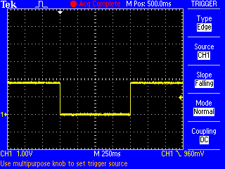
So. I tacked a wire onto the collector of Q2 on a v3.1 modem board (which is connected to the PWKEY pin of the simcom). While running it's 1.8V, it goes to 0V for one second when you do either of: power simcom off power simcom on See attached. The SIM5360 hardware design guide says, "PWRKEY should be pulled low at least 180ms to power on or 500ms to power off the module." So not likely a surprise to whoever wrote our code. So far I haven't figured out how to wedge the simcom on purpose. But my v3.2 module simcom wedged when I was driving on Wednesday. While on the road I checked the iphone ovms app and it showed my location as being a couple of miles from my house even though I was more like 60 miles away. Craig
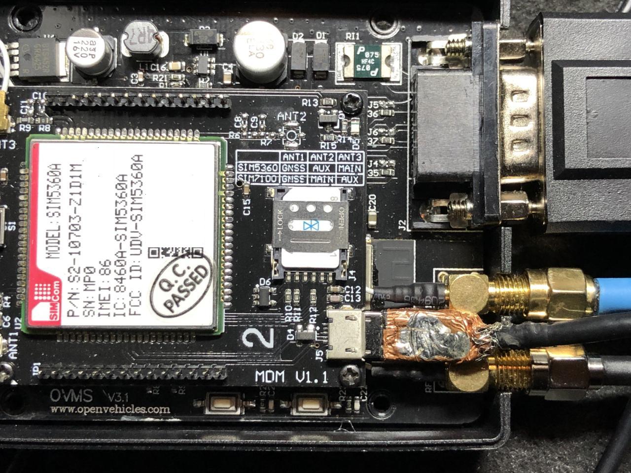
The simcom on one of my modules wedged today and had some time to poke at it. When I turn on simcom debugging I see "AT" commands once a second: D (1199981) simcom: tx scmd ch=0 len=4 : AT D (1200981) simcom: tx scmd ch=0 len=4 : AT but no responses. I wanted to see if I could talk to the simcom via the usb connector on the modem card so I sacrificed a micro usb cable and hacked the molded end off so I could plug it in without detaching the modem board from the main board (see attached). Next I spent a few minutes with a spare module looking for a windows 10 driver. The sim5360 (rar) archive from techship.com didn't work but the windows 8 zip file from here did: https://github.com/botletics/SIM7000-LTE-Shield/tree/master/SIM7000%20Docume... I ended up with four com ports (at, nema, diagnostic, and audio) and was able to talk to the spare modem. Then I went out to plug into the simcom in the car. The first thing I noticed was that the blue led on the modem board is not lit and (as expected) I got nothing from the at com port. For completeness I tried rebooting the module but it help. I now believe wedging the simcom involves running the car for a short amount of time. In this particular case I moved the car out of the garage to make room for some work on my other car. An hour later I moved it back. The run time was 1-2 minutes each time. A bit later when I tested Mark's new ios app I noticed that the car was not reporting a location. I looked at the simcom docs a bit and it's too bad the simcom RESET pin isn't connected to a pio pin. It'll be a couple of days before I'll need the gps to work in case there are ideas of what can be done via software to wake up the simcom. I might trying add a simcom command to set PWKEY to an arbitrary state to see if holding it low for more than one second does anything. Craig
Craig, you'll need log level verbose to see all tx/rx going on (i.e. MUX commands), but debug should be sufficient for the power on sequence. You can test setting the PWRKEY manually by "egpio output 0 1". If the simcom driver is now stuck in the power cycle loop and interferes, you should be able to stop that by "simcom setstate PoweredOff" or "power simcom off". Regards, Michael Am 05.01.20 um 05:16 schrieb Craig Leres:
The simcom on one of my modules wedged today and had some time to poke at it. When I turn on simcom debugging I see "AT" commands once a second:
D (1199981) simcom: tx scmd ch=0 len=4 : AT D (1200981) simcom: tx scmd ch=0 len=4 : AT
but no responses.
I wanted to see if I could talk to the simcom via the usb connector on the modem card so I sacrificed a micro usb cable and hacked the molded end off so I could plug it in without detaching the modem board from the main board (see attached).
Next I spent a few minutes with a spare module looking for a windows 10 driver. The sim5360 (rar) archive from techship.com didn't work but the windows 8 zip file from here did:
https://github.com/botletics/SIM7000-LTE-Shield/tree/master/SIM7000%20Docume...
I ended up with four com ports (at, nema, diagnostic, and audio) and was able to talk to the spare modem.
Then I went out to plug into the simcom in the car. The first thing I noticed was that the blue led on the modem board is not lit and (as expected) I got nothing from the at com port.
For completeness I tried rebooting the module but it help.
I now believe wedging the simcom involves running the car for a short amount of time. In this particular case I moved the car out of the garage to make room for some work on my other car. An hour later I moved it back. The run time was 1-2 minutes each time. A bit later when I tested Mark's new ios app I noticed that the car was not reporting a location.
I looked at the simcom docs a bit and it's too bad the simcom RESET pin isn't connected to a pio pin.
It'll be a couple of days before I'll need the gps to work in case there are ideas of what can be done via software to wake up the simcom. I might trying add a simcom command to set PWKEY to an arbitrary state to see if holding it low for more than one second does anything.
Craig
-- Michael Balzer * Helkenberger Weg 9 * D-58256 Ennepetal Fon 02333 / 833 5735 * Handy 0176 / 206 989 26
Craig, Mark, Thomas, Dimitrie / Thomas just reported a very similar (same?) issue on a EU modem: https://www.openvehicles.com/node/2401 <https://www.openvehicles.com/node/2401#comment-6228> He managed to get a log from the issue, which shows the MUX startup to be broken and remain broken until power down. Specifically, MUX port 2 (just that one) gets stuck in some error state, which does not resolve by a soft power cycle. Thomas also found out even a short hard power cycle won't be sufficient to resolve this:
I found out, when i powered off and 1-2 sec. later on again. the modem got stuck. when i power it off and wait 1 minute and then power it on. it will start normal.
His modem firmware version is 35316B12SIM5360E (B12). @Thomas: there is a B13 available…
I've found later versions (up to B13) and release notes listed only here: https://techship.com/products/simcom-sim5360e-mpcie-sim/
…but you need an account to access them and must accept an NDA.
If you feel lucky you might try that. But it's also possible this is a hardware flaw in all SIM5360 versions. Regards, Michael Am 05.01.20 um 11:12 schrieb Michael Balzer:
Craig,
you'll need log level verbose to see all tx/rx going on (i.e. MUX commands), but debug should be sufficient for the power on sequence.
You can test setting the PWRKEY manually by "egpio output 0 1". If the simcom driver is now stuck in the power cycle loop and interferes, you should be able to stop that by "simcom setstate PoweredOff" or "power simcom off".
Regards, Michael
Am 05.01.20 um 05:16 schrieb Craig Leres:
The simcom on one of my modules wedged today and had some time to poke at it. When I turn on simcom debugging I see "AT" commands once a second:
D (1199981) simcom: tx scmd ch=0 len=4 : AT D (1200981) simcom: tx scmd ch=0 len=4 : AT
but no responses.
I wanted to see if I could talk to the simcom via the usb connector on the modem card so I sacrificed a micro usb cable and hacked the molded end off so I could plug it in without detaching the modem board from the main board (see attached).
Next I spent a few minutes with a spare module looking for a windows 10 driver. The sim5360 (rar) archive from techship.com didn't work but the windows 8 zip file from here did:
https://github.com/botletics/SIM7000-LTE-Shield/tree/master/SIM7000%20Docume...
I ended up with four com ports (at, nema, diagnostic, and audio) and was able to talk to the spare modem.
Then I went out to plug into the simcom in the car. The first thing I noticed was that the blue led on the modem board is not lit and (as expected) I got nothing from the at com port.
For completeness I tried rebooting the module but it help.
I now believe wedging the simcom involves running the car for a short amount of time. In this particular case I moved the car out of the garage to make room for some work on my other car. An hour later I moved it back. The run time was 1-2 minutes each time. A bit later when I tested Mark's new ios app I noticed that the car was not reporting a location.
I looked at the simcom docs a bit and it's too bad the simcom RESET pin isn't connected to a pio pin.
It'll be a couple of days before I'll need the gps to work in case there are ideas of what can be done via software to wake up the simcom. I might trying add a simcom command to set PWKEY to an arbitrary state to see if holding it low for more than one second does anything.
Craig
-- Michael Balzer * Helkenberger Weg 9 * D-58256 Ennepetal Fon 02333 / 833 5735 * Handy 0176 / 206 989 26
On 2020-02-02 02:07, Michael Balzer wrote:
Dimitrie / Thomas just reported a very similar (same?) issue on a EU modem: https://www.openvehicles.com/node/2401 <https://www.openvehicles.com/node/2401#comment-6228>
I have one modem that seems to do this every 1-2 weeks. This weekend I finished a mqtt to nagios bridge so I can tell *when* the modem isn't happy.
He managed to get a log from the issue, which shows the MUX startup to be broken and remain broken until power down.
Specifically, MUX port 2 (just that one) gets stuck in some error state, which does not resolve by a soft power cycle. Thomas also found out even a short hard power cycle won't be sufficient to resolve this:
What I found is that when the modem is stuck, it no longer responds to AT commands and cycling the PWR pin has no effect.
I found out, when i powered off and 1-2 sec. later on again. the modem got stuck. when i power it off and wait 1 minute and then power it on. it will start normal.
I usually count to 10 before replugging.
His modem firmware version is 35316B12SIM5360E (B12).
@Thomas: there is a B13 available…
I've found later versions (up to B13) and release notes listed only here: https://techship.com/products/simcom-sim5360e-mpcie-sim/
…but you need an account to access them and must accept an NDA.
If you feel lucky you might try that. But it's also possible this is a hardware flaw in all SIM5360 versions.
I registered/nda'd and while I have B09 through B13 of the sims5360E firmware but have never found any US versions. I have three modules/modems, two arew B07 (35316B07SIM5360A), one I unsoldered to replace with a sim7600a but is likely the same. Craig
participants (4)
-
 Craig Leres
 -
 Mark Webb-Johnson
 -
 Michael Balzer
 -
 Timo Penttilä