
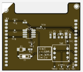
Jaunius, The board will look like this (pcb layout for the first few samples): I’ve tried to make it as generic as possible. SW1 is a four position switch #0 - no connection (with test point that can inject custom voltage if required) #1 - USB 5v. Bus is powered with 5v from the USB (useful for bench testing) #2 - LDO 5v. Bus is powered with 5v using a LDO to regulate down vehicle 12v power #3 - 12v. Bus is powered from vehicle 12v S1 is a on/off switch. When on, it adds a diode+resistor to the K-Line (which is required by some cars for K-line tools being master). Test points everywhere, to help debugging For roadster, SW1 is #2 and S1 is off. It is exposed to the ESP32 as an async port, at 3.3v levels. But the transceiver handles the bus at 5v or 12v. It works with K-line, and should also work with LIN, if required. EGPIO8 is used to enabled/disable the transceiver (normally disabled). Regards, Mark. P.S. Circuit schematic attached.
On 18 May 2020, at 9:14 PM, Jaunius Kapkan <jaunius@gmx.com> wrote:
Very nice.
I wonder can this be optimized to support other metrics? Like using GPS coordinates from CAN instead of the GPS module itself for cars that have it available?
Regards, Jaunius Kapkan [Sent from cellphone]
On 2020-05-11, at 03:57, Mark Webb-Johnson <mark@webb-johnson.net> wrote:
I’ve been spending the last month or so hacking away at TPMS. This has been an ongoing project for the Tesla Roadster that is finally coming to fruition.
About a year or so ago, we already made changes to:
Modify the Tesla Roadster cable to connect the k-line pin on the diagnostic connector through to the DB9 connector on OVMS. We labelled this cable ‘OVT1’. Modify the OVMS module to connect that k-line pin to GEP7.
I’m now working on an optional expansion board that will include a little TJA1027T transceiver and map it to EXP1 and EXP2 (for async comms) and EGPIO8 (for enable/disable) on the ESP32 and MAX. This board will include a jumpered option for K-line master (one diode + one resistor), as well as jumpered powered selection (5v from usb, 5v regulated from car 12v, or direct car 12v) for the K-line bus.
The hand-soldered prototype, using our breakout boards, works well and the K-line async comms works. The screenshot shows OVMS sending a 19 byte request to the ECU (0x0f 0x04 .... 0xf0) and the ECU responding 19 bytes (0x0f 0x05 ... 0xf0) with the 4 tyre IDs. There is a similar command to re-program the ECU with new IDs.
On the firmware side, I am implementing a new vehicle independent ’tpms’ subsystem within OVMS (enabled via configureable option). This will allow sets of tyres to be maintained in the config and read/written to the car's TPMS ECU. The following commands will be available:
tpms status - show status of the system tpms list - list tyre id sets in config tpms read <set> - read IDs from tpms ecu and store in config tyre set tpms write <set> - write IDs to toms ecu from config tyre set tpms set <set> {<id>} - config a set of IDs manually tpms delete <set> - delete the specified tyre set
The initial version will support Tesla Roadster, but the functionality is there for other vehicles to use if they need it (in particular for standard K-line implementations).
Comments/suggestions welcome.
Regards, Mark.
+++Attachments+++
Bench setup, showing (from left to right): Tesla Roadster TPMS ECU opened up Breakout board (power, k, Lin, and can) OVMS for can decode Usb logic analyser Power supply (12v) K-line analysis tool (9010) Windows laptop running k-line software Mac running logic analyser and terminal to OVMS.
<image0.jpeg>
Hand-soldered prototyping board
<image0.jpeg>
Async comms over k-line.
<image1.jpeg>
_______________________________________________ OvmsDev mailing list OvmsDev@lists.openvehicles.com http://lists.openvehicles.com/mailman/listinfo/ovmsdev
OvmsDev mailing list OvmsDev@lists.openvehicles.com http://lists.openvehicles.com/mailman/listinfo/ovmsdev